2006 SUZUKI SWIFT oil pump
[x] Cancel search: oil pumpPage 359 of 1496

Downloaded from www.Manualslib.com manuals search engine Engine Lubrication System: 1E-7
6) After fitting oil pan to cylinder block, run in securing bolts and start tightening at the center: move wrench
outward, tightening one bolt at a time. Tighten bolts
and nuts to specified torque.
Tightening torque
Oil pan bolt (M6) (a): 11 N·m (1.1 kgf-m, 8.0 lb-ft)
Oil pan bolt (M10) (c): 55 N·m (5.5 kgf-m, 40.0 lb-
ft)
Oil pan nut (e): 11 N·m (1.1 kgf-m, 8.0 lb-ft)
7) Install new gasket and drain plug to oil pan. Tighten drain plug to specified torque.
Tightening torque
Oil pan drain plug (b): 35 N·m (3.5 kgf-m, 25.5 lb-
ft)
8) Tighten transaxle stiffener bolts to specified torque. Tightening torque
Transaxle stiffener bolt (d): 55 N·m (5.5 kgf-m,
40.0 lb-ft)
9) Install exhaust manifold stiffener (2) and exhaust No.1 pipe (1) and heated oxygen sensor No.2
(connector color: green) (3) referring to “Exhaust
System Components in Section 1K”. 10) Install clutch housing lower plate (1).
11) Install oil level gauge.
12) Refill engine with engine oil referring to “Engine Oil
and Filter Change in Section 0B”.
13) Verify that there is no en gine oil leakage and exhaust
gas leakage at each connection.
Oil Pan and Oil Pump Strainer CleaningS7RS0B1506006
• Clean sealing surface between oil pan and cylinder block.
Remove oil, old sealant, and dust from sealing
surface.
• Clean oil pump strainer screen (1).(a)
(b)
(c)(e)
(d)I4RS0A150008-01
2
1
3
I4RS0A150003-01
1I4RS0A150004-01
I2RH0B150016-01
Page 360 of 1496

Downloaded from www.Manualslib.com manuals search engine 1E-8 Engine Lubrication System:
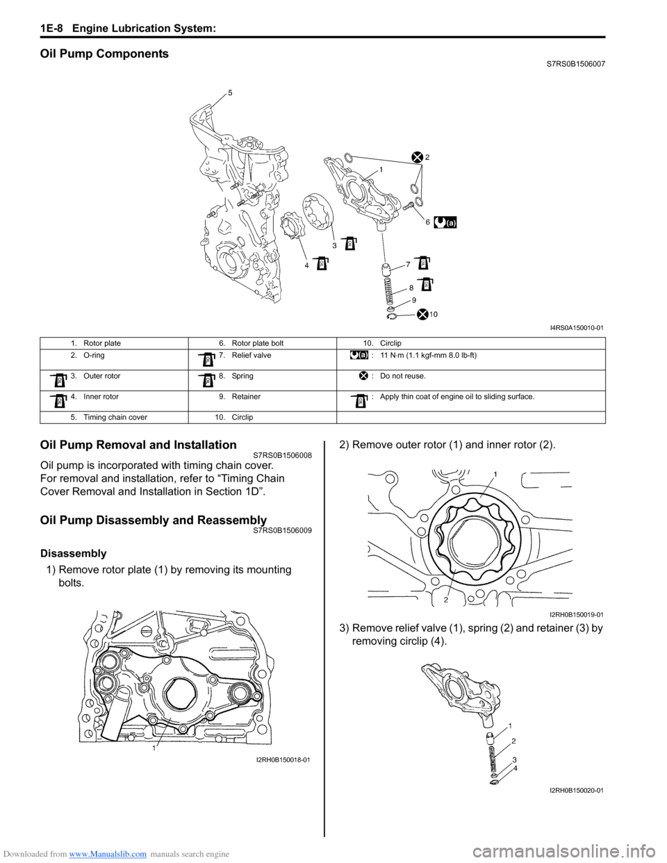
Oil Pump ComponentsS7RS0B1506007
Oil Pump Removal and InstallationS7RS0B1506008
Oil pump is incorporated with timing chain cover.
For removal and installation, refer to “Timing Chain
Cover Removal and Installation in Section 1D”.
Oil Pump Disassembly and ReassemblyS7RS0B1506009
Disassembly1) Remove rotor plate (1) by removing its mounting bolts. 2) Remove outer rotor (1) and inner rotor (2).
3) Remove relief valve (1), spring (2) and retainer (3) by
removing circlip (4).
I4RS0A150010-01
1. Rotor plate 6. Rotor plate bolt10. Circlip
2. O-ring 7. Relief valve : 11 N⋅m (1.1 kgf-mm 8.0 lb-ft)
3. Outer rotor 8. Spring : Do not reuse.
4. Inner rotor 9. Retainer : Apply thin coat of engine oil to sliding surface.
5. Timing chain cover 10. Circlip
I2RH0B150018-01
I2RH0B150019-01
I2RH0B150020-01
Page 361 of 1496

Downloaded from www.Manualslib.com manuals search engine Engine Lubrication System: 1E-9
Reassembly1) Wash, clean and then dry all disassembled parts.
2) Apply thin coat of engine oil to inner and outer rotors, oil seal lip portion, inside surfaces of oil pump case
and plate.
3) Install outer (1) and inner rotors (2) to oil pump case.
4) Apply engine oil to relief valve (1) and spring (2), and install them with retainer (3) and new circlip (4) to
rotor plate (5).
5) Install rotor plate and tighten all bolts to specified torque. After installing plate, check to be sure that
rotors turn smoothly by hand (0.3 N ⋅m (0.03 kgf-m,
0.25 lb-ft) torque or below).
Tightening torque
Oil pump rotor plate bolt (a): 11 N·m (1.1 kgf-m,
8.0 lb-ft)Oil Pump InspectionS7RS0B1506010
Oil Seal
Check oil seal lip for fault or other damage. Replace as
necessary.
Oil Pump
• Check outer (1) and inner rotors (2), rotor plate, and oil pump case for excessive wear or damage.
• Check relief valve (1) for excessive wear or damage
and operates smoothly.
I2RH0B150019-01
I3RM0A150005-01
I2RH0B150022-01
I2RH0B150023-01
I2RH0B150019-01
I2RH0B150025-01
Page 362 of 1496

Downloaded from www.Manualslib.com manuals search engine 1E-10 Engine Lubrication System:
Radial clearance
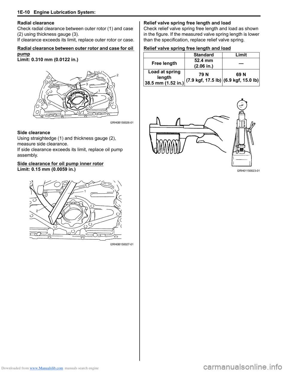
Check radial clearance between outer rotor (1) and case
(2) using thickness gauge (3).
If clearance exceeds its limit, replace outer rotor or case.
Radial clearance between outer rotor and case for oil
pump
Limit: 0.310 mm (0.0122 in.)
Side clearance
Using straightedge (1) and thickness gauge (2),
measure side clearance.
If side clearance exceeds its limit, replace oil pump
assembly.
Side clearance for oil pump inner rotor
Limit: 0.15 mm (0.0059 in.)Relief valve spring free length and load
Check relief valve spring free length and load as shown
in the figure. If the measured valve spring length is lower
than the specification, replace relief valve spring.
Relief valve spring free length and load
I2RH0B150026-01
I2RH0B150027-01
Standard Limit
Free length 52.4 mm
(2.06 in.) —
Load at spring length
38.5 mm (1.52 in.) 79 N
(7.9 kgf, 17.5 lb) 69 N
(6.9 kgf, 15.0 lb)
I2RH01150023-01
Page 363 of 1496

Downloaded from www.Manualslib.com manuals search engine Engine Lubrication System: 1E-11
Specifications
Tightening Torque SpecificationsS7RS0B1507001
NOTE
The specified tightening torque is also described in the following.
“Heat Exchanger Components”
“Oil Pan and Oil Pump Strainer Components”
“Oil Pump Components”
Reference:
For the tightening torque of fastener not specified in this section, refer to “Fasteners Information in Section 0A”.
Special Tools and Equipment
Recommended Service MaterialS7RS0B1508001
NOTE
Required service material is also described in the following.
“Heat Exchanger Components”
“Oil Pan and Oil Pump Strainer Components”
“Oil Pump Components”
Special ToolS7RS0B1508002
Fastening part Tightening torque
Note
N ⋅mkgf-mlb-ft
Oil pressure switch 13 1.3 9.5 �)
Heat exchanger stand bolt 22 2.2 16.0 �)
Oil pump strainer bolt 11 1.1 8.0 �)
Oil pump strainer bracket bolt 11 1.1 8.0 �)
Oil pan bolt (M6) 11 1.1 8.0 �)
Oil pan bolt (M10) 55 5.5 40.0 �)
Oil pan nut 11 1.1 8.0 �)
Oil pan drain plug 35 3.5 25.5 �)
Transaxle stiffener bolt 55 5.5 40.0 �)
Oil pump rotor plate bolt 11 1.1 8.0 �)
MaterialSUZUKI recommended product or Specification Note
Sealant SUZUKI Bond No.1217G P/No.: 99000–31260�)
09915–77310 09915–78211
Oil pressure gauge (0-10kg/
cm2) Oil pressure gauge
attachment
�)�)
Page 364 of 1496

Downloaded from www.Manualslib.com manuals search engine 1F-1 Engine Cooling System:
Engine
Engine Cooling System
General Description
Cooling System DescriptionS7RS0B1601001
The cooling system consists of the radiator cap, radiator, coolant reservoir, hoses, water pump, cooling fan and
thermostat. The radiator is of tube-and-fin type.
Coolant DescriptionS7RS0B1601002
WARNING!
• Do not remove radiator cap to check engine coolant level; check coolant visually at the see-through coolant reservoir. Coolant should be added only to reservoir as necessary.
• As long as there is pressure in the cooling system, the temperature can be considerably higher than the boiling temperature of the solution in the radiator without causing the solution to boil. Removal
of the radiator cap while engine is hot and pressure is high will cause the solution to boil
instantaneously and possibly with explosive force, spewing the solution over engine, fenders and
person removing cap. If the solution contains flammable anti-freeze such as alcohol (not
recommended for use at any time), there is also the possibility of causing a serious fire.
• Check to make sure that engine coolant temperature is cold before removing any part of cooling system.
• Also be sure to disconnect negative cable from battery terminal before removing any part.
The coolant recovery system is standard. The coolant in the radiator expands with heat, and the coolant is overflowed
to the reservoir.
When the system cools down, the coolant is drawn back into the radiator.
The cooling system has be en filled with a quality coolant that is a 50/50 mixture of water and ethylene glycol
antifreeze.
This 50/50 mixture coolant solution provides freezing protection to –36 °C (–33 °F).
• Maintain cooling system freeze protection at –36 °C (–33 °F) to ensure protection against corrosion and loss of
coolant from boiling. This should be done even if freezing temperatures are not expected.
• Add ethylene glycol base coolant when coolant has to be added because of coolant loss or to provide added protection against freezing at temperature lower than –36 °C (–33 °F).
NOTE
• Alcohol or methanol base coolant or plain water alone should not be used in cooling system at any
time as damage to cooling system could occur.
• Coolant must be mixed with deminerated water or distilled water.
Anti-freeze proportioning table
For M/T model For A/T model
Freezing temperature °
C –36 –36
° F –33 –33
Anti-freeze / Anti-corrosion coolant concentration % 50 50
Ratio of compound to cooling water ltr. 3.10/3.10 3.05/3.05
US pt. 6.55/6.55 6.44/6.44
Imp pt. 5.46/5.46 5.37/5.37
Page 403 of 1496

Downloaded from www.Manualslib.com manuals search engine Starting System: 1I-2
ConditionPossible cause Correction / Reference Item
Motor not running (No
operating sound of
magnetic switch) Shift lever switch is not in P or N, or not
adjusted (A/T)
Shift in P or N, or
adjust switch. (A/T)
Battery run down Recharge battery.
Battery voltage too low due to battery
deterioration Replace battery.
Poor contact in battery terminal
connection Retighten or replace.
Loose grounding cable connection Retighten.
Fuse set loose or blown off Tighten or replace.
Poor contacting action of ignition switch
and magnetic switch Replace.
Lead wire coupler loose in place Retighten.
Open-circuit between ignition switch and
magnetic switch Repair.
Open-circuit in pull-in coil Replace magnetic switch.
Brushes are seating poorly or worn
down Repair or replace.
Poor sliding of plunger and/or pinion Repair.
Faulty starting motor control relay “Main Relay, Fuel Pump Relay and Starting
Motor Control Relay Inspection in Section 1C”.
Faulty ECM and its circuit “Inspection of ECM and Its Circuits in Section
1A”.
Motor not running
(Operating sound of
magnetic switch heard) Battery run down
Recharge battery.
Battery voltage too low due to battery
deterioration Replace battery.
Loose battery cable connections Retighten.
Burnt main contact point, or poor
contacting action of magnetic switch Replace magnetic switch.
Brushes are seating poorly or worn
down Repair or replace.
Weakened brush spring Replace.
Burnt commutator Replace armature.
Layer short-circuit of armature Replace.
Crankshaft rotation obstructed Repair.
Starting motor running
but too slow (small
torque) (If battery and
wiring are satisfactory,
inspect starting motor) Insufficient contact
of magnetic switch
main contacts Replace magnetic switch.
Layer short-circuit of armature Replace.
Disconnected, burnt or worn
commutator Repair commutator or replace armature.
Worn brushes Replace brush.
Weakened brush springs Replace spring.
Burnt or abnormally worn end bush Replace bush.
Starting motor running,
but not cranking engine Worn pinion tip
Replace over-running clutch.
Poor sliding of over-running clutch Repair.
Over-running clutch slipping Replace over-running clutch.
Worn teeth of ring gear Replace flywheel (M/T) or drive plate (A/T).
Noise Abnormally worn bush Replace bush.
Worn pinion or worn teeth of ring gear Replace over-running clutch, flywheel (M/T) or
drive plate (A/T).
Poor sliding of pinion (failure in return
movement) Repair or replace.
Worn internal or planetary gear teeth Replace.
Lack of oil in each part Lubricate.
Starting motor does not
stop running Fused contact points of magnetic switch
Replace magnetic switch.
Short-circuit between turns of magnetic
switch coil (layer short-circuit) Replace magnetic switch.
Failure of returning action in ignition
switch Replace.
Page 642 of 1496

Downloaded from www.Manualslib.com manuals search engine 5-ii Table of Contents
DTC P1878: Torque Converter Clutch Shudder .......................................................... 5A-75
DTC P2762: Torque Converter Clutch (TCC) Pressure Control Sole noid Control Circuit
Range /Performance ....................................... 5A-76
DTC P2763: Torque Converter Clutch Pressure Control Sole noid Control Circuit
High ................................................................. 5A-78
DTC P2764: Torque Converter Clutch Circuit Pressure Control Sole noid Control Circuit
Low ................................................................. 5A-80
Inspection of TCM and Its Circuits .................... 5A-82
TCM Power and Ground Circuit Check ............. 5A-86
Brake Interlock System Inspection .................... 5A-87
Repair Instructions ........... .................................5A-88
Learning Control Initializat ion ............................ 5A-88
A/T Fluid Level Check ....................................... 5A-89
A/T Fluid Change .............................................. 5A-90
Select Lever Components ... .............................. 5A-90
Select Lever Assembly Removal and Installation ....................................................... 5A-90
Select Lever Knob Installa tion........................... 5A-90
Select Lever Inspection .... ................................. 5A-91
“3” Position Switch Inspec tion ........................... 5A-91
Shift Lock Solenoid Inspec tion .......................... 5A-91
Shift Lock Solenoid Replacement ..................... 5A-91
Select Cable Components ................................ 5A-92
Select Cable Removal and Installation ............. 5A-92
Select Cable Adjustment ................................... 5A-93
Key Interlock Cable Removal and Installation... 5A-93
Transmission Range Sensor (Shift Switch) Inspection and Adjustment .............................. 5A-95
Output Shaft Speed Sensor Removal and Installation ....................................................... 5A-96
Output Shaft Speed Sensor Inspection ............. 5A-96
Input Shaft Speed Sensor Removal and Installation ....................................................... 5A-96
Input Shaft Speed Sensor Inspection................ 5A-97
Transmission Fluid Temperature Sensor Removal and Installation ................................. 5A-97
Transmission Fluid Temperature Sensor Inspection ........................................................ 5A-98
Solenoid Valves (Shift Solenoid Valves and Timing Solenoid Valve) Removal and
Installation ....................................................... 5A-98
Solenoid Valves (Shift Solenoid Valves, and Timing Solenoid Valve) Inspection .................. 5A-99
Pressure Control Soleno id Valves (Pressure
Control Solenoid and TCC Pressure Control
Solenoid) Removal and Inst allation .............. 5A-101
Pressure Control Solenoid Valve Inspection ... 5A-101
Transmission Control Module (TCM) Removal and Installation ............................... 5A-102
A/T Relay Inspection ....................................... 5A-103
Differential Side Oil Seal Replacement ........... 5A-103
A/T Fluid Cooler Hoses Replacement ............. 5A-104
Automatic Transaxle Unit Components........... 5A-105
Automatic Transaxle Unit Dismounting and Remounting ................................................... 5A-106
Automatic Transaxle Asse mbly Components . 5A-108 Automatic Transaxle Unit
Disassembly........... 5A-110
Oil Pump Assembly Components ................... 5A-121
Oil Pump Assembly Disassembly and Reassembly .................................................. 5A-122
Oil Pump Assembly Inspection ....................... 5A-122
Direct Clutch Assembly Components.............. 5A-124
Direct Clutch Assembly Preliminary Check ..... 5A-124
Direct Clutch Assembly Disassembly and Reassembly .................................................. 5A-125
Direct Clutch Assembly Inspection.................. 5A-127
Forward and Reverse Clutch Assembly Components .................................................. 5A-128
Forward and Reverse Clutch Assembly Preliminary Check ......................................... 5A-129
Forward and Reverse Clutch Assembly Disassembly and Reassembly ...................... 5A-129
Forward and Reverse Clutch Assembly Inspection ...................................................... 5A-133
2nd Brake Piston Assembly Components ....... 5A-134
2nd Brake Piston Assembly Disassembly and Reassembly .................................................. 5A-134
Transaxle Rear Cover (O/D and 2nd Coast Brake Piston) Assembly Components........... 5A-135
Transaxle Rear Cover (O/D and 2nd Coast Brake Piston) Assembly Disassembly and
Reassembly .................................................. 5A-136
Transaxle Rear Cover (O/D and 2nd Coast Brake Piston) Assembly Inspection............... 5A-137
Countershaft Assembly Co mponents.............. 5A-138
Countershaft Assembly Disassembly and Reassembly .................................................. 5A-138
Valve Body Assembly Components ................ 5A-139
Valve Body Assembly Disassembly and Reassembly .................................................. 5A-140
Differential Assembly Components ................. 5A-141
Differential Assembly Disassembly and Reassembly .................................................. 5A-142
Differential Assembly Inspection ..................... 5A-143
Torque Converter Housing Disassembly and Reassembly .................................................. 5A-144
Transaxle Case Disassembly and Reassembly .................................................. 5A-146
Automatic Transaxle Unit Inspection and Adjus
tment .................................................... 5A-147
Automatic Transaxle Unit Assembly ............... 5A-150
Specifications .................. .................................5A-167
Tightening Torque Specifications .................... 5A-167
Special Tools and Equipmen t .........................5A-168
Recommended Service Material ..................... 5A-168
Special Tool .................................................... 5A-168
Manual Transmission/Tr ansaxle ............ 5B-1
General Description .............................................5B-1
Manual Transaxle Construction and Servicing .... 5B-1
Diagnostic Information and Procedures ............5B-3 Manual Transaxle Symptom Diagnosis............... 5B-3
Repair Instructions ............ ..................................5B-3
Manual Transaxle Oil Change............................. 5B-3
Differential Side Oil Seal Replacement ............... 5B-4