2006 SUZUKI SWIFT oil pressure sensor
[x] Cancel search: oil pressure sensorPage 950 of 1496

Downloaded from www.Manualslib.com manuals search engine 7B-2 Air Conditioning System: Manual Type
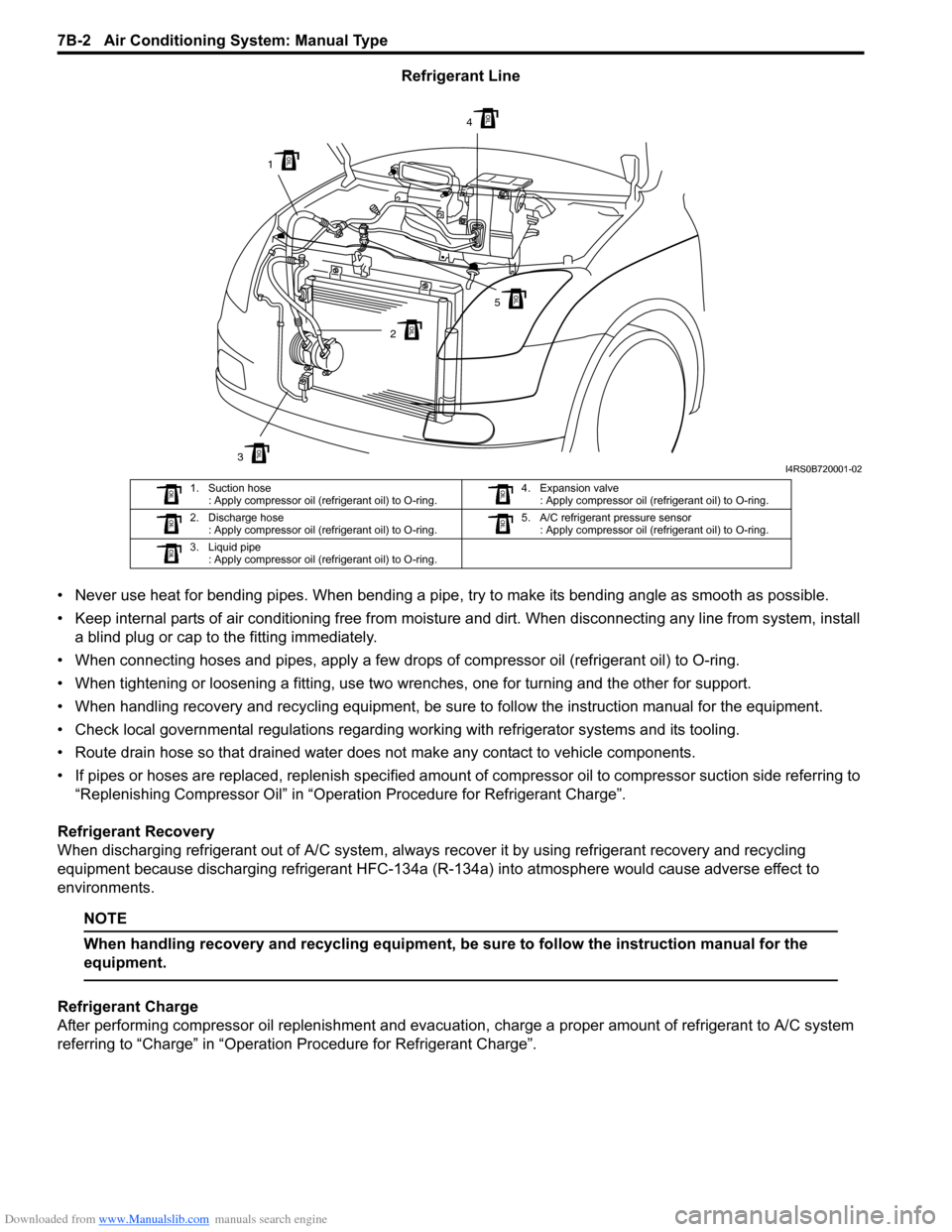
Refrigerant Line
• Never use heat for bending pipes. When bending a pipe , try to make its bending angle as smooth as possible.
• Keep internal parts of air conditioning free from moistu re and dirt. When disconnecting any line from system, install
a blind plug or cap to the fitting immediately.
• When connecting hoses and pipes, apply a few drops of compressor oil (refrigerant oil) to O-ring.
• When tightening or loosening a fitting, use two wrenches, one for turning and the other for support.
• When handling recovery and recycling equipment, be sure to follow the instruction manual for the equipment.
• Check local governmental regulations regarding working with refrigerator systems and its tooling.
• Route drain hose so that drained water does not make any contact to vehicle components.
• If pipes or hoses are replaced, replenish specified amount of compressor oil to compre ssor suction side referring to
“Replenishing Compressor Oil” in “Operation Procedure for Refrigerant Charge”.
Refrigerant Recovery
When discharging refrigerant out of A/C system, always recover it by using refrigerant recovery and recycling
equipment because discharging refrigerant HFC-134a (R-1 34a) into atmosphere would cause adverse effect to
environments.
NOTE
When handling recovery and recycling equipment, be sure to follow the instruction manual for the
equipment.
Refrigerant Charge
After performing compressor oil replenishment and evacuat ion, charge a proper amount of refrigerant to A/C system
referring to “Charge” in “Operation Procedure for Refrigerant Charge”.
3
1
2
4
5
I4RS0B720001-02
1. Suction hose : Apply compressor oil (refrigerant oil) to O-ring. 4. Expansion valve
: Apply compressor oil (refrigerant oil) to O-ring.
2. Discharge hose : Apply compressor oil (refrigerant oil) to O-ring. 5. A/C refrigerant pressure sensor
: Apply compressor oil (refrigerant oil) to O-ring.
3. Liquid pipe : Apply compressor oil (refrigerant oil) to O-ring.
Page 957 of 1496

Downloaded from www.Manualslib.com manuals search engine Air Conditioning System: Manual Type 7B-9
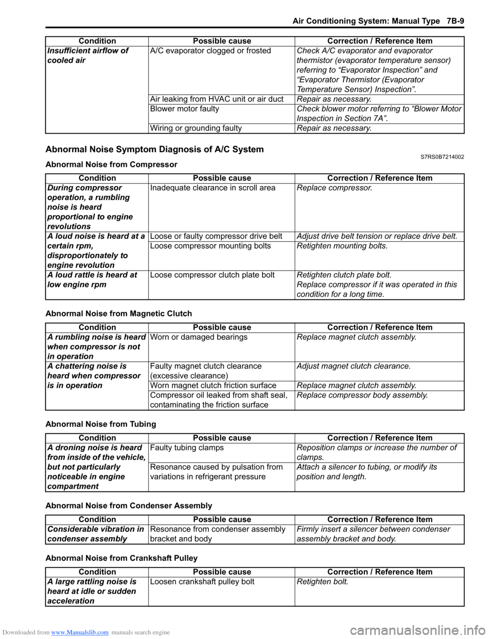
Abnormal Noise Symptom Diagnosis of A/C SystemS7RS0B7214002
Abnormal Noise from Compressor
Abnormal Noise from Magnetic Clutch
Abnormal Noise from Tubing
Abnormal Noise from Condenser Assembly
Abnormal Noise from Crankshaft PulleyInsufficient airflow of
cooled air
A/C evaporator clogged or frosted
Check A/C evaporator and evaporator
thermistor (evaporator temperature sensor)
referring to “Evaporator Inspection” and
“Evaporator Thermistor (Evaporator
Temperature Sensor) Inspection”.
Air leaking from HVAC unit or air duct Repair as necessary.
Blower motor faulty Check blower motor referring to “Blower Motor
Inspection in Section 7A”.
Wiring or grounding faulty Repair as necessary.
Condition Possible cause Correction / Reference Item
Condition
Possible cause Correction / Reference Item
During compressor
operation, a rumbling
noise is heard
proportional to engine
revolutions Inadequate clearance in scroll area
Replace compressor.
A loud noise is heard at a
certain rpm,
disproportionately to
engine revolution Loose or faulty compressor drive belt
Adjust drive belt tension or replace drive belt.
Loose compressor mounting bolts Retighten mounting bolts.
A loud rattle is heard at
low engine rpm Loose compressor clutch plate bolt
Retighten clutch plate bolt.
Replace compressor if it was operated in this
condition for a long time.
Condition Possible cause Correction / Reference Item
A rumbling noise is heard
when compressor is not
in operation Worn or damaged bearings
Replace magnet clutch assembly.
A chattering noise is
heard when compressor
is in operation Faulty magnet clutch clearance
(excessive clearance)
Adjust magnet clutch clearance.
Worn magnet clutch friction surface Replace magnet clutch assembly.
Compressor oil leaked from shaft seal,
contaminating the friction surface Replace compressor body assembly.
Condition
Possible cause Correction / Reference Item
A droning noise is heard
from inside of the vehicle,
but not particularly
noticeable in engine
compartment Faulty tubing clamps
Reposition clamps or increase the number of
clamps.
Resonance caused by pulsation from
variations in re frigerant pressure Attach a silencer to tubing, or modify its
position and length.
Condition
Possible cause Correction / Reference Item
Considerable vibration in
condenser assembly Resonance from condenser assembly
bracket and body Firmly insert a silenc
er between condenser
assembly bracket and body.
Condition Possible cause Correction / Reference Item
A large rattling noise is
heard at idle or sudden
acceleration Loosen crankshaft pulley bolt
Retighten bolt.
Page 974 of 1496

Downloaded from www.Manualslib.com manuals search engine 7B-26 Air Conditioning System: Manual Type
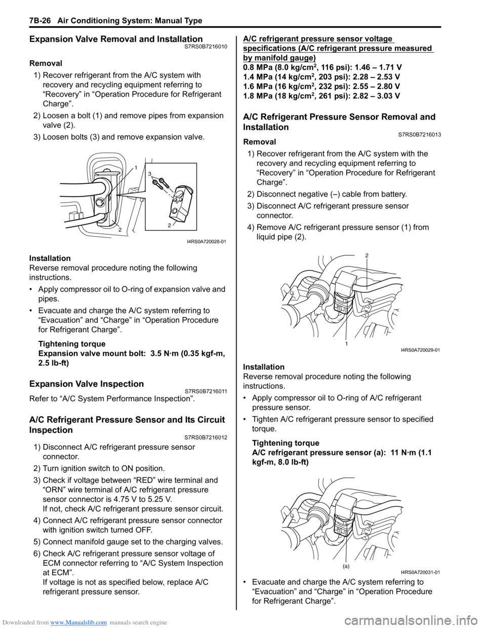
Expansion Valve Removal and InstallationS7RS0B7216010
Removal1) Recover refrigerant fr om the A/C system with
recovery and recycling equipment referring to
“Recovery” in “Operation Procedure for Refrigerant
Charge”.
2) Loosen a bolt (1) and remove pipes from expansion valve (2).
3) Loosen bolts (3) and remove expansion valve.
Installation
Reverse removal procedure noting the following
instructions.
• Apply compressor oil to O-ring of expansion valve and pipes.
• Evacuate and charge the A/C system referring to “Evacuation” and “Charge” in “Operation Procedure
for Refrigerant Charge”.
Tightening torque
Expansion valve mount bolt: 3.5 N·m (0.35 kgf-m,
2.5 lb-ft)
Expansion Valve InspectionS7RS0B7216011
Refer to “A/C System Performance Inspection”.
A/C Refrigerant Pressure Sensor and Its Circuit
Inspection
S7RS0B7216012
1) Disconnect A/C refrigerant pressure sensor connector.
2) Turn ignition switch to ON position.
3) Check if voltage between “RED” wire terminal and “ORN” wire terminal of A/C refrigerant pressure
sensor connector is 4.75 V to 5.25 V.
If not, check A/C refrigerant pressure sensor circuit.
4) Connect A/C refrigerant pressure sensor connector with ignition switch turned OFF.
5) Connect manifold gauge set to the charging valves.
6) Check A/C refrigerant pressure sensor voltage of ECM connector referring to “A/C System Inspection
at ECM”.
If voltage is not as specified below, replace A/C
refrigerant pressure sensor. A/C refrigerant pressure sensor voltage
specifications (A/C refrigerant pressure measured
by manifold gauge)
0.8 MPa (8.0 kg/cm2, 116 psi): 1.46 – 1.71 V
1.4 MPa (14 kg/cm2, 203 psi): 2.28 – 2.53 V
1.6 MPa (16 kg/cm2, 232 psi): 2.55 – 2.80 V
1.8 MPa (18 kg/cm2, 261 psi): 2.82 – 3.03 V
A/C Refrigerant Pressure Sensor Removal and
Installation
S7RS0B7216013
Removal
1) Recover refrigerant from the A/C system with the recovery and recycling equipment referring to
“Recovery” in “Operation Procedure for Refrigerant
Charge”.
2) Disconnect negative (–) cable from battery.
3) Disconnect A/C refrigerant pressure sensor connector.
4) Remove A/C refrigerant pressure sensor (1) from liquid pipe (2).
Installation
Reverse removal procedure noting the following
instructions.
• Apply compressor oil to O-ring of A/C refrigerant
pressure sensor.
• Tighten A/C refrigerant pressure sensor to specified torque.
Tightening torque
A/C refrigerant pressure sensor (a): 11 N·m (1.1
kgf-m, 8.0 lb-ft)
• Evacuate and charge the A/C system referring to “Evacuation” and “Charge” in “Operation Procedure
for Refrigerant Charge”.
1
2 2
3
I4RS0A720028-01
1 2I4RS0A720029-01
(a)I4RS0A720031-01
Page 980 of 1496

Downloaded from www.Manualslib.com manuals search engine 7B-32 Air Conditioning System: Manual Type
Relief Valve Removal and InstallationS7RS0B7216030
Removal1) Recover refrigerant fr om the A/C system with
recovery and recycling equipment referring to
“Recovery” in “Operation Procedure for Refrigerant
Charge”.
2) Remove relief valve (1) from compressor (2). Installation
Reverse removal procedure nothing the following
instructions.
• Use new O-ring.
• Apply compressor oil to O-ring.
• Tighten relive valve to the specified torque.
Tightening torque
Relief valve (a): 8 N·m (0.8 kgf-m, 6.0 lb-ft)
• Evacuate and charge the A/C system referring to “Evacuation” and “Charge” in “Operation Procedure
for Refrigerant Charge”.
Specifications
Tightening Torque SpecificationsS7RS0B7217001
NOTE
The specified tightening torque is also described in the following.
“Compressor Assembly Components”
Reference:
For the tightening torque of fastener not specified in this section, refer to “Fasteners Information in Section 0A”.
12I4RS0A720048-01
(a)I4RS0A720049-01
Fastening part
Tightening torque
Note
N ⋅mkgf-mlb-ft
Receiver/dryer bolt 10 1.0 7.5 �)
Expansion valve mount bolt 3.5 0.35 2.5 �)
A/C refrigerant pressure sensor 11 1.1 8.0 �)
Armature plate bolt 15 1.5 11.0 �)
Relief valve 8 0.8 6.0 �)
Page 1168 of 1496

Downloaded from www.Manualslib.com manuals search engine 9-ii Table of Contents
List of Connectors ........................................... 9A-103
C Connector .................................................... 9A-103
D Connector (M16A engine) ........................... 9A-104
E Connector .................................................... 9A-104
G Connector .................................................... 9A-106
J Connector ..................................................... 9A-108
K Connector .................................................... 9A-109
L Connector..................................................... 9A-109
M Connector (SPORT model) ......................... 9A-111
O Connector .................................................... 9A-111
R Connector .................................................... 9A-111
Lighting Systems .................................... 9B-1
Component Location ........... ................................9B-1
Lighting System Component s Location............... 9B-1
Interior Light System Location............................. 9B-2
Diagnostic Information and Procedures ............ 9B-2 Headlight Symptom Diagnosis ............................ 9B-2
Headlight Leveling System Symptom Diagnosis (If Equipped) ..................................... 9B-2
Turn Signal and Hazard Warning Light Symptom Diagnosis .......................................... 9B-3
Clearance, Tail and License Plate Light Symptom Diagnosis .......................................... 9B-3
Back-Up Light Symptom Diagnosis..................... 9B-4
Brake Light Symptom Diagnosis ......................... 9B-4
Front Fog Light Symptom Diagnosis (If Equipped) .......................................................... 9B-4
Interior Light Symptom Diagnosis ....................... 9B-5
Repair Instructions ..............................................9B-5 Headlight Housing Removal and Installation ...... 9B-5
Headlight Bulb Replacemen t............................... 9B-6
Headlight Aiming Adjustment with Screen .......... 9B-6
Headlight Switch (in Lighting Switch) Removal and Installation ................................... 9B-8
Headlight Switch (in Lighting Switch) Inspection .......................................................... 9B-8
Hazard Warning Switch Removal and Installation ......................................................... 9B-8
Hazard Warning Switch Inspection ..................... 9B-9
Brake Light Switch Inspection ............................. 9B-9
Turn Signal Light Switch (in Lighting Switch) Removal and Installation ................................... 9B-9
Turn Signal Light Switch (in Lighting Switch) Inspection .......................................................... 9B-9
Turn Signal and Hazard Warning Relay Removal and Installation ................................... 9B-9
Turn Signal and Hazard Warning Relay Inspection ........................................................ 9B-10
License Light Removal and Installation............. 9B-10
Front Fog Light Removal and Installation (If Equipped) ........................................................ 9B-11
Front Fog Light Bulb Replacement (If Equipped) ........................................................ 9B-11
Front Fog Light Switch Inspection (If Equipped) ........................................................ 9B-11
Front Fog Light Relay Inspection (If Equipped) ........................................................ 9B-11
Front Fog Light Aiming Adjustment with Screen (If Equipped) ....................................... 9B-12 Headlight Leveling Switch Inspection (If
Equipped) ........................................................ 9B-13
Headlight Leveling Actuator Inspection (If Equipped) ........................................................ 9B-13
Instrumentation / Driver Info. / Horn ...... 9C-1
Precautions ...........................................................9C-1 Precautions in Diagnosing Troubles for Combination Meter ............................................9C-1
General Description .............................................9C-1 CAN Communication System Description...........9C-1
Auto Volume Co ntrol System Description (If
Equipped) ..........................................................9C-3
Schematic and Routing Diagram ........................9C-4 Combination Meter Circuit Diagram ....................9C-4
Component Location ............ ...............................9C-6
Audio System Component Location ....................9C-6
Diagnostic Information and Procedures ............9C-6 Speedometer and VSS Symp tom Diagnosis ......9C-6
Tachometer Symptom Diagnosis ........................9C-6
Engine Coolant Temperature (ECT) Meter Symptom Diagnosis ..........................................9C-7
Fuel Meter Symptom Diagnosis ..........................9C-7
Low Fuel Warning Light Symptom Diagnosis .....9C-7
Oil Pressure Warning Light Symptom Diagnosis ..........................................................9C-8
Brake and Parking Brake Warning Light Symptom Diagnosis ..........................................9C-8
Seat Belt Reminder Light Symptom Diagnosis (If Equipped)......................................................9C-8
A/T Shift Position Indicator Symptom Diagnosis (A/T Model).......................................9C-9
Charge Warning Light Sy mptom Diagnosis ........9C-9
Main Beam (High Beam) Indicator Symptom Diagnosis ..........................................................9C-9
Warning Buzzer Circuit Sy mptom Diagnosis ....9C-10
Cigarette Lighter Symptom Diagnosis (If Equipped) ........................................................9C-10
Horn Symptom Diagnosis .................................9C-10
Information Display Symptom Diagnosis (If Equipped) ........................................................9C-11
Clock Symptom Diagnosis (If Equipped)...........9C-12
Audio System Symptom Diagnosis (If Equipped) ........................................................9C-12
Remote Audio Control Switch Symptom Diagnosis (If Equipped) ...................................9C-13
Navigation Symptom Diagnosis (If Equipped)...9C-14
Repair Instructions ............ ................................9C-14
Ignition Switch Removal and Installation...........9C-14
Ignition Switch Inspection..................................9C-14
Combination Meter Removal and Installation ...9C-15
Fuel Level Sensor Removal and Installation .....9C-15
Fuel Level Sensor Inspection ............................9C-15
Oil Pressure Switch Remova l and Installation ..9C-15
Oil Pressure Switch Inspec tion .........................9C-16
Engine Coolant Temperature (ECT) Sensor Inspection ........................................................9C-16
Brake Fluid Level Switch Inspection .................9C-16
Parking Brake Switch Inspec tion.......................9C-16
Page 1175 of 1496
![SUZUKI SWIFT 2006 2.G Service Workshop Manual Downloaded from www.Manualslib.com manuals search engine Wiring Systems: 9A-4
How to Read Connector Layout DiagramS7RS0B9101004
[A-1]: Harness symbol and corresponding harness name
A: Battery harness SUZUKI SWIFT 2006 2.G Service Workshop Manual Downloaded from www.Manualslib.com manuals search engine Wiring Systems: 9A-4
How to Read Connector Layout DiagramS7RS0B9101004
[A-1]: Harness symbol and corresponding harness name
A: Battery harness](/manual-img/20/7607/w960_7607-1174.png)
Downloaded from www.Manualslib.com manuals search engine Wiring Systems: 9A-4
How to Read Connector Layout DiagramS7RS0B9101004
[A-1]: Harness symbol and corresponding harness name
A: Battery harness
B: A/C harness
C: Engine harness
D: Injector harness
E: Main harness, Oil pressure switch wire, Console wire
G: Instrument panel harness
J: Side door wire (Power window)
K: Interior light harness, Rear speaker wire, Roof wire
L: Floor harness, G sensor wire (Fuel pump harness)
M: Rear bumper harness
O: Rear end door harness
Q: Air bag/Pretensioner harness
R: (Fuel pump wire)
[A-2]: Connector Number
[B]: Ground point No.
12
11
[B] [B]
Connector code
[A-1] [A-2]L 36
L13 L15
R01
L14
L12
L11L10
L09 L36
R02
L24
L25
L33
L28
L20 L26 (TO O01)
{
L05
L16
L32
L19
L01 (TO G01)
L02 (TO E04)
L03 (TO E05)
L42
R05
R04
L07 (TO K02)
I2RH01910901-01
Page 1182 of 1496

Downloaded from www.Manualslib.com manuals search engine 9A-11 Wiring Systems:
C: Engine harnessNo./Color Connective position No./Color Connective positionC01/GRY IAC valve C22/- Generator #2
C02/GRY IG Coil #1 C23/BLK Starting motor #1
C03/GRY IG Coil #2 C24/- Starting motor #2
C04/GRY Fuel injector #1 C25/GR Y VSS (Vehicle speed sensor)
C05/GRY Fuel injector #2 C26/GRY Knock sensor
C06/GRY Fuel injector #3 C27/BLU (A/
T) Input shaft speed sensor
C07/GRY Fuel injector #4 C28/GRY
(A/T) Trans axle range sensor
C08/BLK or GRY CMP sensor C29/GRY
(A/T) Shift solenoid
C09/BLK ECT sensor C30/BLK
(M/T) Back-up light switch
C10/GRY EGR stepper motor C31/- Main fuse box C11/BLK Throttle position sensor C32/GRY
(IF EQPD) Current sensor
C12/BLK MAP sensor C33/- Main fuse box
C13/BLK MAF sensor C34/N (A/T) TCM
C14/BLK EVAP canister purge valve C35/N (A/T) TCM
C15/GRY Heated oxygen sensor #1 C36/N Main harness (To E24)
C16/GRN Heated oxygen sensor #2 C37/GRY ECM C17/BLK A/C compressor C38/- Weld splice C18/N Oil pressure switch C39/- Weld splice
C19/BLU VVT solenoid C40/- Weld splice
C20/GRY CKP sensor C41/- Weld splice
C21/GRY or BLK Generator #1
Page 1184 of 1496

Downloaded from www.Manualslib.com manuals search engine 9A-13 Wiring Systems:
C: Engine harness
D: Oil pressure switch wireNo./Color Connective position No./Color Connective position
C02/GRY IG Coil #1 C24/- Starting motor #2
C03/GRY IG Coil #2 C23/BLK Starting motor #1
C04/GRY Fuel injector #1 C25/GRY
(A/T) VSS (Vehicle speed sensor)
C05/GRY Fuel injector #2 C26/GRY Knock shaft speed sensor
C06/GRY Fuel injector #3 C27/BLU (A/
T) Input shaft speed sensor
C07/GRY Fuel injector #4 C28/GRY
(A/T) Trans axle range sensor
C08/BLK CMP sensor C29/GRY
(A/T) Shift solenoid
C09/BLK ECT sensor C30/BLK
(M/T) Back-up light switch
C10/GRY EGR stepper motor C31/- Main fuse box C12/BLK MAP sensor C32/GRY Current sensor
C13/BLK MAF sensor C33/- Main fuse box
C14/BLK EVAP canister purge valve C34/N (A/T) TCM
C15/BLK Heated oxygen sensor #1 C35/N (A/T) TCM
C16/GRN Heated oxygen sensor #2 C36/N Main harness (To E24) C17/BLK A/C compressor C37/GRY ECM C18/N Oil pressure switch wire (To D02) C38/- Weld splice
C19/BLU VVT solenoid C39/- Weld splice
C20/GRY CKP sensor C40/- Weld splice C21/BLK Generator #1 C42/BLK Electric throttle body C22/- Generator #2
No./Color Connective position No./ColorConnective position
D01/N Oil pressure switch D02/GRY Engine harness (To C18)