2006 SUZUKI SWIFT Wheel cylinder
[x] Cancel search: Wheel cylinderPage 635 of 1496

Downloaded from www.Manualslib.com manuals search engine Electronic Stability Program: 4F-61
Front Wheel Encoder On-Vehicle InspectionS7RS0B4606033
Before inspect front wheel encoder, remove front drive
shaft or front wheel spindle referring to “Front Drive Shaft
Assembly Removal and Installation in Section 3A”.
• Check encoder (1) for being crack, damaged or deformed.
• Turn wheel and check if encoder rotation is free from eccentricity and looseness.
• Check that no foreign material is attached. If any faulty is found, cl ean encoder or replace wheel
bearing. Refer to “Front Wheel Hub, Steering Knuckle
and Wheel Bearing Removal and Installation in
Section 2B”.
Front Wheel Encoder Removal and InstallationS7RS0B4606034
CAUTION!
Front wheel encoder is included in front
wheel bearing. If front wheel encoder needs
to replaced, replace it as a front wheel
bearing.
For removal and installation of front wheel bearing,
referring to “Front Wheel Hub, Steering Knuckle and
Wheel Bearing Removal and Installation in Section 2B”.
Rear Wheel Encoder On-Vehicle InspectionS7RS0B4606035
Before inspect rear wheel encoder, hoist vehicle and
remove wheel.
• Check encoder (1) for being crack, damaged or deformed.
• Turn wheel and check if encoder rotation is free from eccentricity and looseness.
• Check that no foreign material is attached. If any faulty is found, cl ean encoder or replace rear
wheel hub assembly. Refer to “Rear Wheel Hub
Removal and Installati on in Section 2C”.
Rear Wheel Encoder Removal and InstallationS7RS0B4606036
CAUTION!
Rear wheel encoder is included in rear wheel
hub assembly. If rear wheel encoder needs to
replaced, replace it as a rear wheel hub
assembly.
For removal and installation of front wheel hub
assembly, referring to “Rear Wheel Hub Removal and
Installation in Section 2C”.
Master Cylinder Pressure Sensor On-Vehicle
Inspection
S7RS0B4606016
1) Calibrate yaw rate / G sens or assembly referring to
“Sensor Calibration”.
2) Check that basic brake system other than ESP ®
refer to “Brakes Diagnosi s Note in Section 4A”.
3) Connect SUZUKI scan tool to data link connector (DLC) (1) with ignition switch OFF.
Special tool
(A): SUZUKI scan tool
1
I5JB0A450034-01
1
I6RS0B460038-03
(A)
1
I4RS0B450003-01
Page 636 of 1496

Downloaded from www.Manualslib.com manuals search engine 4F-62 Electronic Stability Program:
4) Turn ignition switch to ON position and select menu “DATA LIST” mode of SUZUKI scan tool. Refer to
scan tool operator's manual for further derails.
5) When brake pedal is released, check “Master Cyl Press” under “DATA LIST” of SUZUKI scan tool.
If pressure is out of specification, replace ESP ®
hydraulic unit / cont rol module assembly.
Master cylinder pressure specification
Brake pedal released: 0 ± 0.8 MPa (0 ± 8 kg/cm2, 0
± 113 psi)
6) Hoist vehicle and remove right-side front wheel.
7) Connect special tool with rubber hose (1) to Front brake caliper bleeder plug (2).
Special tool
(A): 09956–02311
8) When bleeder plug loosen and depress brake pedal to make special tool gauge reading 10 MPa (100 kg/
cm
2, 1422 psi), check “Master Cyl Press” under
“DATA LIST” of SUZUKI scan tool.
If pressure displayed on SUZUKI scan tool is out of
specification, replace ESP ® hydraulic unit / control
module assembly.
Master cylinder pressure specification
Brake pedal depressed 10 MPa (100 kg/cm2, 1422
psi): 10 ± 1.2 MPa (100 ± 12 kg/cm2, 1422 ± 170
psi)
9) After completing the check, turn ignition switch to
OFF position and disconnect SUZUKI scan tool from
DLC.
10) Tighten bleeder plug and bleed air from brake system, referring to “Air Bleeding of Brake System in
Section 4A”.
Yaw Rate / G Sensor Assembly On-Vehicle
Inspection
S7RS0B4606017
Lateral G Inspection
1) Calibrate yaw rate / G sens or assembly referring to
“Sensor Calibration”.
2) Park and level the vehicle with parking brake and fix wheels with chokes.
3) Check yaw rate / G sensor assembly installation
condition. 4) Connect SUZUKI scan tool to data link connector
(DLC) (1) with ignition switch OFF.
Special tool
(A): SUZUKI scan tool
5) Turn ignition switch to ON position and select menu “DATA LIST” mode of SUZUKI scan tool. Refer to
scan tool operator's manual for further derails.
6) Check “G Sensor (lateral)” under “DATA LIST” of SUZUKI scan tool in the following vehicle conditions.
• Level condition
• Right-up condition
• Left-up condition
If Lateral G condition is ou t of specification, replace
yaw rate / G sensor assembly.
Lateral G sp ecification
2
(A)
1
I6JB01460025-01
Vehicle condition G Sensor (lateral)
Level condition 0 ± 0.1 G
Right-up condition 0.1 ± 0.1 G
Left-up condition –0.1 ± 0.1 G
[A]: Right-up condition “a”: Approx 350 mm (13.78 in.)
[B]: Left-up condition 1. Safety stand
(A)
1
I4RS0B450003-01
[A]
[B]“a”
1
“a”1
I6RS0B460039-02
Page 643 of 1496

Downloaded from www.Manualslib.com manuals search engine Table of Contents 5-iii
Gear Shift Control Lever and Cable Components...................................................... 5B-5
Gear Shift Control Le ver and Cable Removal
and Installation .................................................. 5B-6
Gear Select Control Cable Adjustment ............... 5B-6
Back Up Light Switch Removal and Installation ......................................................... 5B-7
Back Up Light Switch Inspection ......................... 5B-7
Manual Transaxle Unit Components ................... 5B-8
Manual Transaxle Unit Dismounting and Remounting....................................................... 5B-9
Gear Shift and Sele ct Shaft Assembly
Components.................................................... 5B-11
Gear Shift and Sele ct Shaft Assembly
Removal and Installation................................. 5B-11
Gear Shift and Select Shaft Disassembly and Assembly ........................................................ 5B-12
Manual Transaxle Assembly Components........ 5B-13
Fifth Gear Disassembly and Assembly ............. 5B-14
Manual Transaxle Assembly Disassembly and Reassembly ............................................. 5B-16
Transaxle Right Case Disassembly and Assembly ........................................................ 5B-23
Transaxle Left Case Disassembly and Assembly ........................................................ 5B-24
Input Shaft and Countershaft Components....... 5B-25
Input Shaft Assembly Disassembly and Reassembly .................................................... 5B-26
Countershaft Assembly Disassembly and Reassembly .................................................... 5B-28
Synchronizer Parts Inspec tion .......................... 5B-31
Gear Shift Shaft Components ........................... 5B-31
5th and Reverse Gear Shift Shafts Disassembly and Assembly ............................ 5B-32
Gear Shift Shaft and Fork Inspection ................ 5B-32
Differential Components ................................... 5B-33
Differential Disassembly and Assembly ............ 5B-33
Specifications ..................................................... 5B-35
Tightening Torque Specifications ...................... 5B-35
Special Tools and Equipmen t ........................... 5B-36
Recommended Service Material ....................... 5B-36 Special Tool ...................................................... 5B-36
Clutch ................
.............................. ......... 5C-1
General Description .............................................5C-1
Clutch Construction .............................................5C-1
Diagnostic Information and Procedures ............5C-2 Clutch System Symptom Diagnosis ....................5C-2
Repair Instructions ........... ...................................5C-2
Clutch Pedal Inspection ......................................5C-2
Clutch Fluid Level Inspection ..............................5C-3
Air Bleeding of Clutch System.............................5C-3
Clutch Pedal Position (CPP) Switch Removal and Installation ..................................................5C-4
Clutch Pedal Position (CPP) Switch Inspection and Adjustment ................................5C-5
Clutch Fluid Pipe and Hose Components ...........5C-5
Clutch Fluid Pipe Removal and Installation.........5C-6
Clutch Fluid Pipe Inspection................................5C-6
Clutch Master Cylinder Removal and Installation .........................................................5C-6
Clutch Operating Cylinder Removal and Installation .........................................................5C-7
Clutch Operating Cylinder Inspection..................5C-7
Clutch Pedal and Clutch Pedal Bracket Components ......................................................5C-7
Clutch Cover, Clutch Disc and Flywheel Components ......................................................5C-8
Clutch Cover, Clutch Disc and Flywheel Removal and Installation ...................................5C-8
Clutch Cover, Clutch Disc and Flywheel Inspection ........................................................5C-10
Clutch Release Syst em Removal and
Installation .......................................................5C-11
Clutch Release System Inspection ...................5C-13
Specifications .................... .................................5C-13
Tightening Torque Specifications ......................5C-13
Special Tools and Equipmen t ...........................5C-14
Recommended Service Material .......................5C-14
Special Tool ......................................................5C-14
Page 854 of 1496

Downloaded from www.Manualslib.com manuals search engine 5C-2 Clutch:
Diagnostic Information and Procedures
Clutch System Symptom DiagnosisS7RS0B5304001
Repair Instructions
Clutch Pedal InspectionS7RS0B5306001
Cylinder Push Rod Play “A”1) Press clutch pedal (1) gradually with finger, stop when slight increase of resistance is felt and
measure how much pedal has moved (push rod
play) as represented by “A” as shown.
Push rod play
“A”: Max. 3 mm (0.12 in.)
2) If “A” is not within specification, replace master cylinder (3) or pedal arm (2). Clutch Pedal Free Travel “B”
1) Depress clutch pedal (1), stop the moment clutch resistance is felt, and measure how much pedal has
moved (clutch pedal free travel) as represented by
“B” in figure.
Clutch pedal free travel
“B”
: 2 – 8 mm (0.08 – 0.31 in.)
2) If “B” is not within specification, check pedal arm (2) and master cylinder (3) and replace defective part.
Condition Possible cause Correction / Reference Item
Slipping Improper clutch pedal free travel Replace master cylinder or clutch pedal arm.
Worn or oily clutch disc facing Replace disc.
Warped disc, pressure plate or flywheel
surface Replace disc, clutch cover or flywheel.
Weakened diaphragm spring Replace clutch cover.
Master cylinder piston or seal cup not
returning Replace master cylinder.
Dragging clutch Improper clutch pedal free travel Replace master cylinder or clutch pedal arm.
Weakened diaphragm spring, or worn
spring tip Replace clutch cover.
Rusted input shaft splines Lubricate.
Damaged or worn splines of transaxle
input shaft Replace input shaft.
Excessively wobbly clutch disc Replace disc.
Clutch facings broken or dirty with oil Replace disc.
Fluid leakage Repair or replace.
Clutch vibration Glazed (glass-like) clutch facings Repair or replace disc.
Clutch facings dirty with oil Replace disc.
Release bearing slides unsmoothly on
input shaft bearing retainer Lubricate or replace input shaft bearing
retainer.
Wobbly clutch disc, or poor facing
contact Replace disc.
Weakened torsion springs in clutch disc Replace disc.
Clutch disc rivets loose Replace disc.
Distorted pressure plate or flywheel
surface Replace clutch cover or flywheel.
Weakened engine mounting Replace engine mounting.
Loosened engine mounting bolt or nut Retighten engine mounting bolt or nut.
Noisy clutch Worn or broken release bearing Replace release bearing.
Input shaft front bearing worn down Replace input shaft bearing.
Excessive rattle of clutch disc hub Replace disc.
Cracked clutch disc Replace disc.
Pressure plate and diaphragm spring
rattling Replace clutch cover.
Grabbing clutch Clutch disc facings soaked with oil Replace disc.
Clutch disc facings excessively worn Replace disc.
Rivet heads showing out of facing Replace disc.
Weakened torsion springs Replace disc.
Page 855 of 1496

Downloaded from www.Manualslib.com manuals search engine Clutch: 5C-3
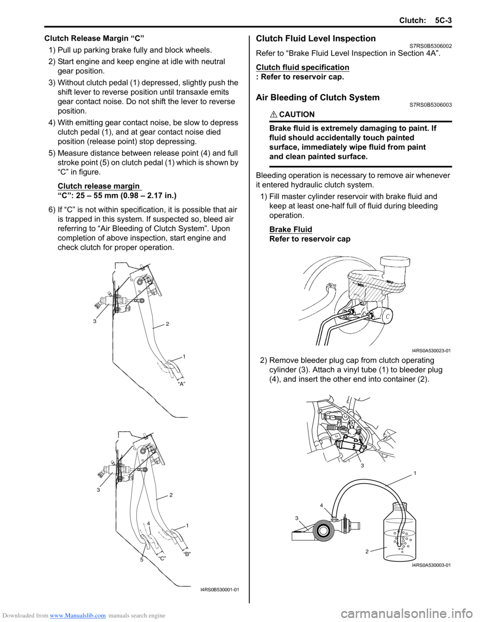
Clutch Release Margin “C”1) Pull up parking brake fully and block wheels.
2) Start engine and keep engine at idle with neutral gear position.
3) Without clutch pedal (1) dep ressed, slightly push the
shift lever to re verse position until transaxle emits
gear contact noise. Do not shift the lever to reverse
position.
4) With emitting gear contact noise, be slow to depress clutch pedal (1), and at gear contact noise died
position (release point) stop depressing.
5) Measure distance between release point (4) and full stroke point (5) on clutch pedal (1) which is shown by
“C” in figure.
Clutch release margin
“C”: 25 – 55 mm (0.98 – 2.17 in.)
6) If “C” is not within specificat ion, it is possible that air
is trapped in this system. If suspected so, bleed air
referring to “Air Bleeding of Clutch System”. Upon
completion of above inspection, start engine and
check clutch for proper operation.
Clutch Fluid Level InspectionS7RS0B5306002
Refer to “Brake Fluid Level Inspection in Section 4A”.
Clutch fluid specification
: Refer to reservoir cap.
Air Bleeding of Clutch SystemS7RS0B5306003
CAUTION!
Brake fluid is extremely damaging to paint. If
fluid should accidentally touch painted
surface, immediately wipe fluid from paint
and clean painted surface.
Bleeding operation is necessary to remove air whenever
it entered hydraulic clutch system.
1) Fill master cylinder reservoir with brake fluid and keep at least one-half full of fluid during bleeding
operation.
Brake Fluid
Refer to reservoir cap
2) Remove bleeder plug cap from clutch operating cylinder (3). Attach a vinyl tube (1) to bleeder plug
(4), and insert the other end into container (2).
2
1
“A”
3
2
1
3
“B”
“C”
4
5
I4RS0B530001-01
I4RS0A530023-01
3 4 1
2
3
I4RS0A530003-01
Page 865 of 1496

Downloaded from www.Manualslib.com manuals search engine Clutch: 5C-13
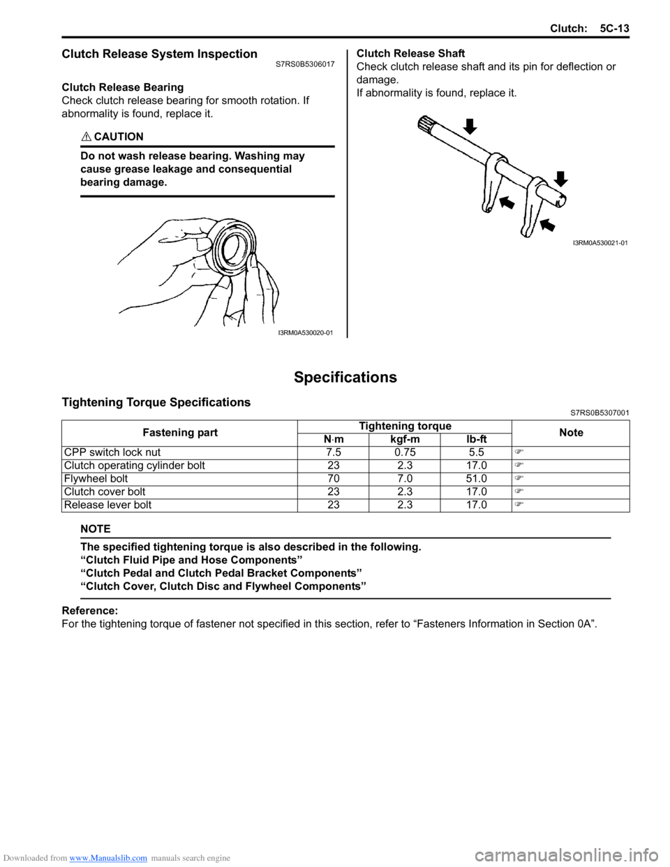
Clutch Release System InspectionS7RS0B5306017
Clutch Release Bearing
Check clutch release bearing for smooth rotation. If
abnormality is found, replace it.
CAUTION!
Do not wash release bearing. Washing may
cause grease leakage and consequential
bearing damage.
Clutch Release Shaft
Check clutch release shaft and its pin for deflection or
damage.
If abnormality is found, replace it.
Specifications
Tightening Torque SpecificationsS7RS0B5307001
NOTE
The specified tightening torque is also described in the following.
“Clutch Fluid Pipe and Hose Components”
“Clutch Pedal and Clutch Pedal Bracket Components”
“Clutch Cover, Clutch Disc and Flywheel Components”
Reference:
For the tightening torque of fastener not specified in this section, refer to “Fasteners Information in Section 0A”.
I3RM0A530020-01
I3RM0A530021-01
Fastening part Tightening torque
Note
N ⋅mkgf-mlb-ft
CPP switch lock nut 7.5 0.75 5.5 �)
Clutch operating cylinder bolt 23 2.3 17.0 �)
Flywheel bolt 70 7.0 51.0 �)
Clutch cover bolt 23 2.3 17.0 �)
Release lever bolt 23 2.3 17.0 �)
Page 867 of 1496

Downloaded from www.Manualslib.com manuals search engine Table of Contents 6- i
6
Section 6
CONTENTS
Steering
Precautions ................................................. 6-1
Precautions............................................................. 6-1
Precautions on Steering........................................ 6-1
Steering General Diagnosi s.................... 6A-1
Precautions........................................................... 6A-1
Precautions for Steering Diagnosis ..................... 6A-1
Diagnostic Information and Procedures ............ 6A-2 Steering Symptom Diagnosis .............................. 6A-2
Steering Wheel and Column ................... 6B-1
Precautions........................................................... 6B-1
Service Precautions of Steering Wheel and Column.............................................................. 6B-1
General Description ............................................. 6B-1 Steering Wheel and Column Construction .......... 6B-1
Diagnostic Information and Procedures ............ 6B-2 Checking Steering Column for Accident Damage ............................................................ 6B-2
Repair Instructions .............................................. 6B-3 Steering Wheel and Column Construction .......... 6B-3
Steering Wheel Removal and Installation ........... 6B-4
Contact Coil Cable Assembly Removal and Installation ......................................................... 6B-5
Centering Contact Coil Cable Assembly ............. 6B-6
Contact Coil Cable Assembly Inspection ............ 6B-6
Steering Angle Sensor Removal and Installation ......................................................... 6B-6
Steering Angle Sensor Inspection ....................... 6B-6
Steering Column Removal and Installation ......... 6B-7
Steering Column Inspecti on ................................ 6B-8
Ignition Switch Cylinder Assembly Removal and Installation (Non- Keyless Start Model)...... 6B-9
Steering Lock Assembly (Ignition Switch) Removal and Installation................................... 6B-9
Steering Lower Shaft Removal and Installation ....................................................... 6B-10
Specifications ..................................................... 6B-11
Tightening Torque Specifications ...................... 6B-11
Special Tools and Equipmen t ........................... 6B-11
Special Tool ...................................................... 6B-11
Power Assisted Steering System........... 6C-1
Precautions........................................................... 6C-1 Steering System Note .........................................6C-1
Precautions in Diagnosing Troubles ...................6C-1
General Description .............................................6C-2 P/S System Description ......................................6C-2
EPS Diagnosis General Descr iption ...................6C-3
On-Board Diagnostic System Description ...........6C-3
Schematic and Routing Diagram ........................6C-4 EPS System Wiring Circuit Diagram ...................6C-4
Diagnostic Information and Procedures ............6C-5 EPS System Check .............. ...............................6C-5
“EPS” Warning Light Check . ...............................6C-8
DTC Check..........................................................6C-8
DTC Clearance ...................................................6C-9
DTC Table ...........................................................6C-9
Scan Tool Data .................................................6C-11
Visual Inspection ...............................................6C-12
P/S System Symptom Diagnosis ......................6C-12
Serial Data Link Circuit Check ..........................6C-13
“EPS” Warning Light Do es Not Come ON with
Ignition Switch Turn ed ON before Engine
Starts ...............................................................6C-15
“EPS” Warning Light Remains ON Steady after Engine Starts ..........................................6C-16
DTC C1113: Steering Torque Sensor (Main and Sub) Circuit Correlation ............................6C-17
DTC C1114: Steering Torque Sensor Reference Power Supply Circuit .....................6C-19
DTC C1117: Steering Torque Sensor Failure Signal Circuit Low ...........................................6C-21
DTC C1118: Steering Torque Sensor Failure Signal Circuit High...........................................6C-22
DTC C1119: Steering Torque Sensor Power Supply Circuit ..................................................6C-24
DTC C1121 / C1123 / C1124: VSS Circuit
Failure .............................................................6C-26
DTC C1122: Engine Speed Signal....................6C-28
DTC C1141 / C1142 / C1143 / C1145: P/S Motor Circuit Failure ........................................6C-30
DTC C1153: P/S Control Module Power Supply Circuit Voltage Low .............................6C-32
DTC C1155: P/S Control Module Failure ..........6C-33
P/S Control Module Power Supply and Ground Circuit Check ......................................6C-34
Inspection of P/S Control Module and Its Circuits ............................................................6C-35
Page 880 of 1496

Downloaded from www.Manualslib.com manuals search engine 6B-9 Steering Wheel and Column:
Ignition Switch Cylinder Assembly Removal
and Installation (Non- Keyless Start Model)
S7RS0B6206008
Removal1) Disconnect negative (–) cable at battery.
2) Disable air bag system referring to “Disabling Air Bag System in Section 8B”.
3) Remove steering column upper and lower covers.
4) Remove immobilizer co ntrol module referring to
“Immobilizer Control Modu le (ICM) Removal and
Installation in Section 10C”.
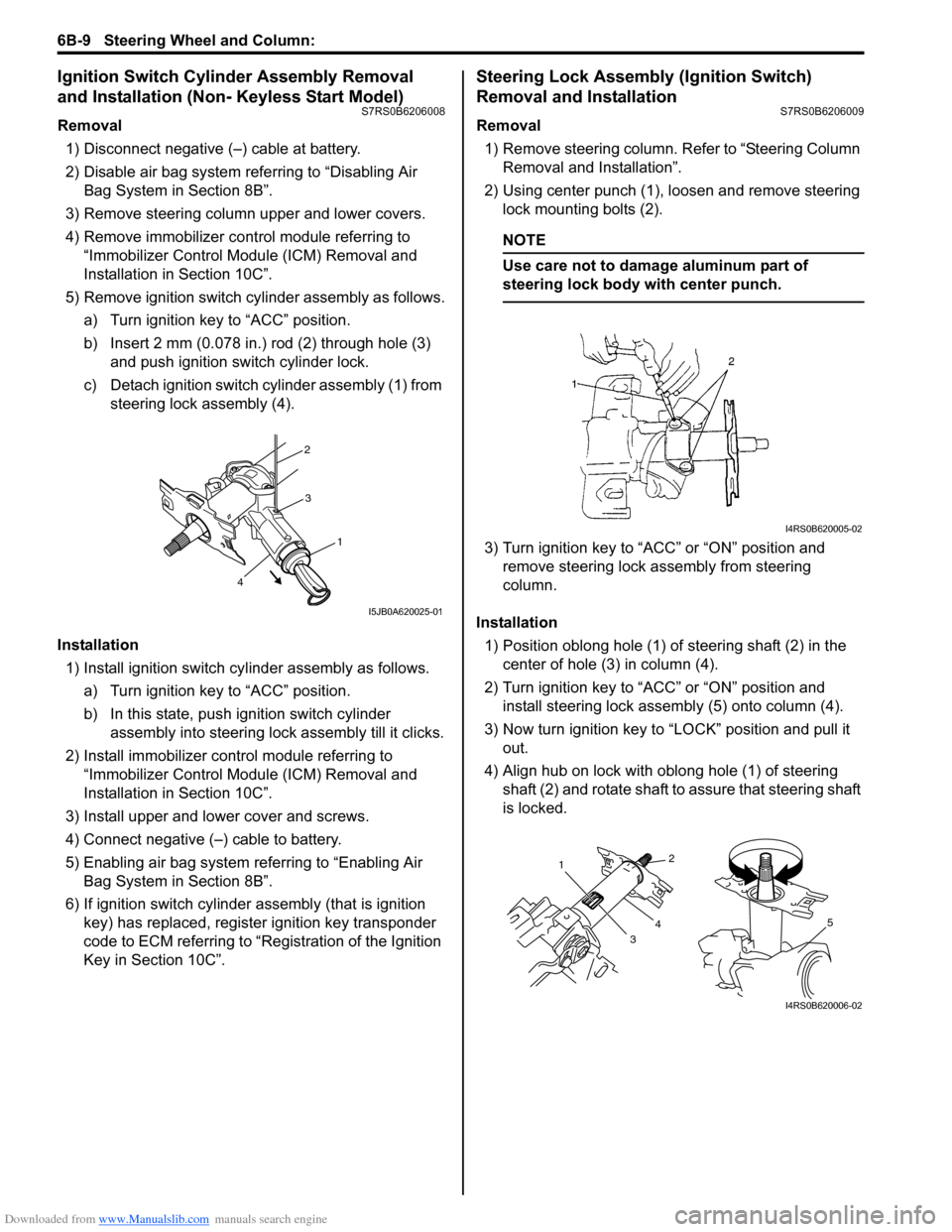
5) Remove ignition switch cy linder assembly as follows.
a) Turn ignition key to “ACC” position.
b) Insert 2 mm (0.078 in.) rod (2) through hole (3) and push ignition switch cylinder lock.
c) Detach ignition switch cylinder assembly (1) from steering lock assembly (4).
Installation 1) Install ignition switch cy linder assembly as follows.
a) Turn ignition key to “ACC” position.
b) In this state, push ignition switch cylinder assembly into steering lock assembly till it clicks.
2) Install immobilizer cont rol module referring to
“Immobilizer Control Modu le (ICM) Removal and
Installation in Section 10C”.
3) Install upper and lower cover and screws.
4) Connect negative (–) cable to battery.
5) Enabling air bag system referring to “Enabling Air Bag System in Section 8B”.
6) If ignition switch cylinder assembly (that is ignition
key) has replaced, register ignition key transponder
code to ECM referring to “R egistration of the Ignition
Key in Section 10C”.
Steering Lock Assembly (Ignition Switch)
Removal and Installation
S7RS0B6206009
Removal
1) Remove steering column. Refer to “Steering Column
Removal and Installation”.
2) Using center punch (1), loosen and remove steering lock mounting bolts (2).
NOTE
Use care not to damage aluminum part of
steering lock body with center punch.
3) Turn ignition key to “ACC” or “ON” position and remove steering lock a ssembly from steering
column.
Installation 1) Position oblong hole (1) of steering shaft (2) in the center of hole (3) in column (4).
2) Turn ignition key to “ACC” or “ON” position and install steering lock assemb ly (5) onto column (4).
3) Now turn ignition key to “LOCK” position and pull it out.
4) Align hub on lock with oblong hole (1) of steering shaft (2) and rotate shaft to assure that steering shaft
is locked.
2
3
1
4
I5JB0A620025-01
I4RS0B620005-02
1
32
4
5
I4RS0B620006-02