Page 886 of 1496

Downloaded from www.Manualslib.com manuals search engine 6C-4 Power Assisted Steering System:
Schematic and Routing Diagram
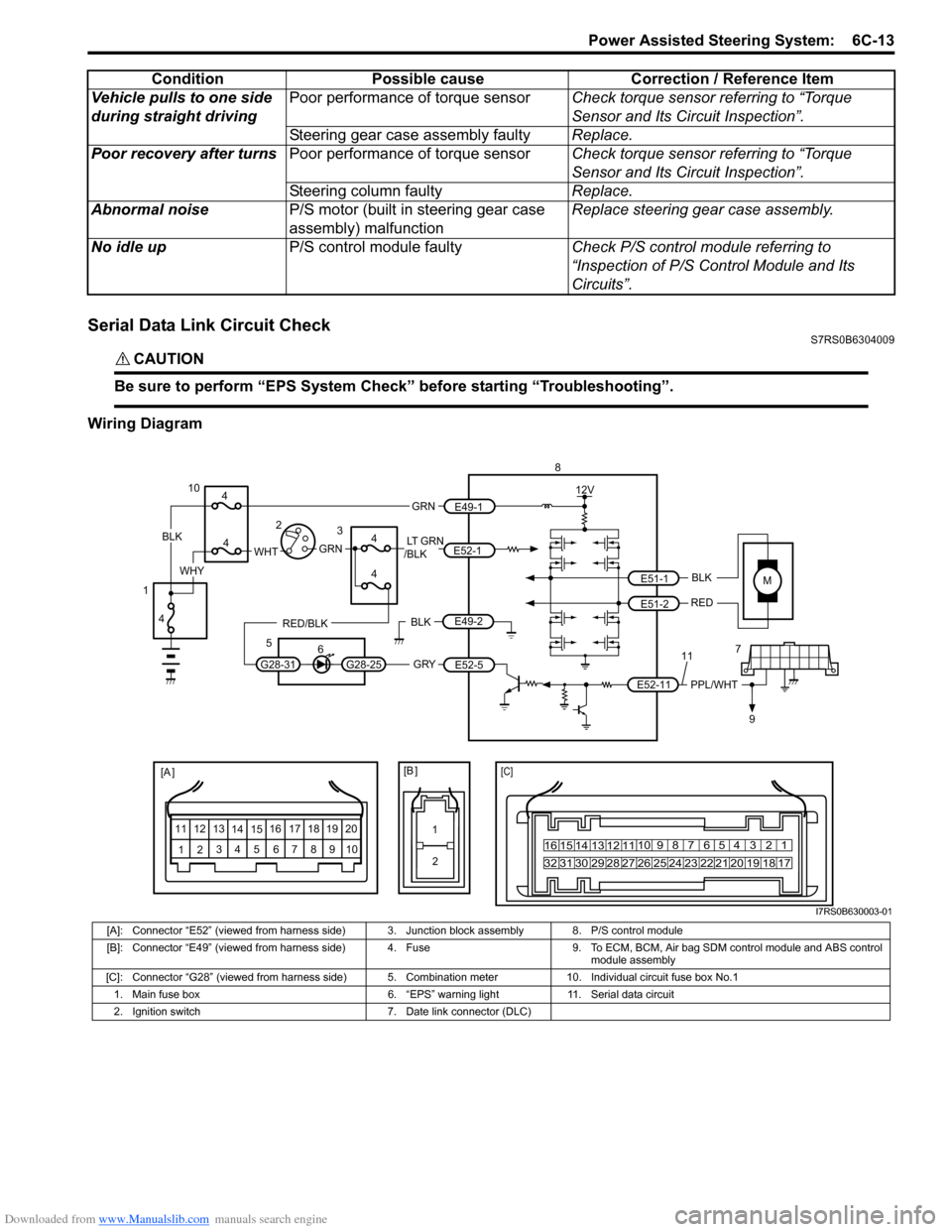
EPS System Wiring Circuit DiagramS7RS0B6302001
M
5V
BRNRED/
BLU
BLK
RED
WHT
BLU
GRN
BRN YEL
E52-11
E52-14E52-12
E23-4
E23-26
E23-25 E51-1
E51-2
E52-18
E53-5
E53-7
E52-6
E52-8
E53-2
E52-9
E52-16
E52-19
GRY
PPL/WHT
[A ]
[E ]
12 3
4 5 67
89
11
10
12 13
141516
17 18 19 20
1
2
[B ][C ]
1210 9 8 7654 3 21
16 15 14 13 12 11
26 25 24 2322 21 20 19 18 17
32 31 30 29 28 27
[D]
5V
PPL
E52-4
11
12
13 14
15
10
9
16
12V
5V
5V
12V
REDE52-20E53-6
E53-4
E53-1
7654321
5
REDRED/
BLKWHT
6WHTWHT/BLKWHTBLK
12V
12V
17BLK
GRY
LT GRN
/BLK
E52-1
E52-5
E49-1
GRNGRNWHTBLK
WHY
G28-25G28-31
RED/BLK
18
3
4
4
7 8
4
4
1 2
4
E49-2BLK
I7RS0B630002-01
[A]: Connector “E52” (viewed from harness side) 4. Fuse 12. P/S motor
[B]: Connector “E49” (viewed from harness side ) 5. Left-front wheel speed sensor 13. Shield
[C]: Connector “E51” (viewed from harness side) 6 . Right-front wheel speed sensor 14. Torque sensor
[D]: Connector “G28” (viewed from harness side) 7. Combination meter 15. Torque sensor amplifier
[E]: Connector “E53” (viewed from harness side) 8. “EPS” warning light16. To ECM, BCM, Air bag SDM and ABS control module assembly
1. Main fuse box 9. Date link connector (DLC) 17. ABS/ESP ® control module
2. Ignition switch 10. ECM18. Individual circuit fuse box No.1
3. Junction block assembly 11. P/S control module
Page 895 of 1496

Downloaded from www.Manualslib.com manuals search engine Power Assisted Steering System: 6C-13
Serial Data Link Circuit CheckS7RS0B6304009
CAUTION!
Be sure to perform “EPS System Check” before starting “Troubleshooting”.
Wiring DiagramVehicle pulls to one side
during straight driving
Poor performance of torque sensor
Check torque sensor referring to “Torque
Sensor and Its Circuit Inspection”.
Steering gear case assembly faulty Replace.
Poor recovery after turns Poor performance of torque sensor Check torque sensor referring to “Torque
Sensor and Its Circuit Inspection”.
Steering column faulty Replace.
Abnormal noise P/S motor (built in steering gear case
assembly) malfunction Replace steering gear case assembly.
No idle up P/S control module faulty Check P/S control module referring to
“Inspection of P/S Control Module and Its
Circuits”.
Condition Possible cause Correction / Reference Item
MBLK
RED
E52-11 E51-1
E51-2PPL/WHT
[A ]
12
3
4 5 67
89
11
10
12 13
141516
17 18 19 2010 9 8 7654 3 21
16 15 14 13 12 11
26 25 24 2322 21 20 19 18 17
32 31 30 29 28 27
[C]
8
79
12V
[B ]
11
12
GRY
LT GRN
/BLK
E52-1
E52-5
E49-1
GRNGRNWHTBLK
WHY
G28-25G28-31
RED/BLK
10
3
4
4
5 6
4
4
1 2
4
E49-2BLK
I7RS0B630003-01
[A]: Connector “E52” (viewed from harness side) 3. Junction block assembly 8. P/S control module
[B]: Connector “E49” (viewed from harness side) 4. Fuse 9. T o ECM, BCM, Air bag SDM control module and ABS control
module assembly
[C]: Connector “G28” (viewed from harness side) 5. Comb ination meter 10. Individual circuit fuse box No.1
1. Main fuse box 6. “EPS” warning light 11. Serial data circuit
2. Ignition switch 7. Date link connector (DLC)
Page 908 of 1496

Downloaded from www.Manualslib.com manuals search engine 6C-26 Power Assisted Steering System:
DTC C1121 / C1123 / C1124: VSS Circuit FailureS7RS0B6304017
DTC C1121: No Vehicle Speed Signal (60 Seconds or More)
DTC C1123: No Vehicle Speed Signal (30 Seconds or More)
DTC C1124: Vehicle Speed Performance (Impossible Deceleration)
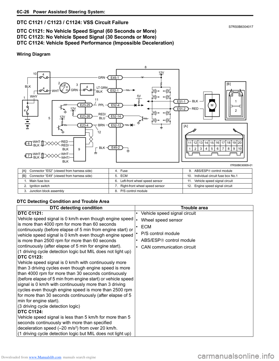
Wiring Diagram
DTC Detecting Condition and Trouble Area
M
BRNRED/
BLU
BLK
RED
E52-14
E52-12
E23-4
E23-26
E23-25 E51-1
E51-2
[A ]
12
3
4 5 67
89
11
10
12 13
141516
17 18 19 20
5V
PPL
E52-4
8
5
12V
E49-2BLK
12V
12V
6REDRED/ BLKWHT
7WHTWHT/BLKWHTBLK BLK
111
2
[B ]
9
LT GRN
/BLKE52-1 E49-1
GRNGRNWHTBLK
WHY
10
3
4
4
4
4
1 2
12
I7RS0B630009-01
[A]: Connector “E52” (viewed from harness side)
4. Fuse9. ABS/ESP® control module
[B]: Connector “E49” (viewed from harness si de)5. ECM 10. Individual circuit fuse box No.1
1. Main fuse box 6. Left-front wheel speed sensor11. Vehicle speed signal circuit
2. Ignition switch 7. Right-front wheel speed sensor 12. Engine speed signal circuit
3. Junction block assembly 8. P/S control module
DTC detecting condition Trouble area
DTC C1121:
Vehicle speed signal is 0 km/h even though engine speed
is more than 4000 rpm for more than 60 seconds
continuously (before elapse of 5 min from engine start) or
vehicle speed signal is 0 km/h even though engine speed
is more than 2500 rpm for more than 60 seconds
continuously (after elapse of 5 min for engine start).
(1 driving cycle detection logic but MIL does not light up)
DTC C1123:
Vehicle speed signal is 0 km/h with continuously more
than 3 driving cycles even though engine speed is more
than 4000 rpm for more than 30 seconds continuously
(before elapse of 5 min from engine start) or vehicle speed
signal is 0 km/h with continuously more than 3 driving
cycles even though engine speed is more than 2500 rpm
for more than 30 seconds continuously (after elapse of 5
min for engine start).
(3 driving cycle detection logic)
DTC C1124:
Vehicle speed signal is less than 5 km/h for more than 5
seconds continuously with more than specified
deceleration speed (–20 m/s
2) from over 20 km/h.
(1 driving cycle detection logic but MIL does not light up) • Vehicle speed signal circuit
• Wheel speed sensor
•ECM
• P/S control module
• ABS/ESP®
control module
• CAN communication circuit
Page 954 of 1496

Downloaded from www.Manualslib.com manuals search engine 7B-6 Air Conditioning System: Manual Type
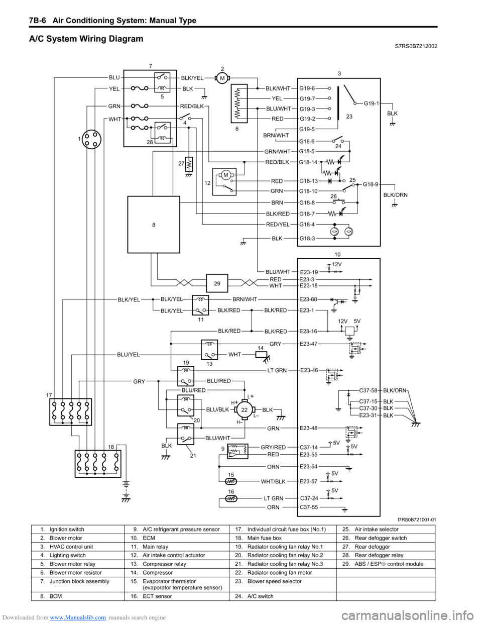
A/C System Wiring DiagramS7RS0B7212002
BLK/REDBLK/RED
BLK/YELBLK/YEL
BLK/YEL
BRN/WHT
12V5V
5V 5V
5V11
E23-1
E23-60
BLK/REDBLK/REDE23-16
E23-57WHT/BLK
9
13
E23-55C37-14GRY/REDRED
BLK
ORN
E23-47 GRY
WHTBLU/YEL
RED/BLK
14 3
1
15
5
7
BLK
2
M
12VBLU/WHTE23-19
C37-24
C37-55ORN
5V
LT GRN16
G18-3
G18-4
G18-7
G18-8
G18-10
G18-13
G18-5
G18-6
G19-5
G19-2
G19-3
G19-7
G19-6
G19-1
G18-9
G18-14
BLK/WHT
YEL
BLU/WHT
RED
BRN/WHT
GRN/WHT
RED/BLK
RED
GRN
BRN
BLK/RED
RED/YEL
BLK
BLK/YEL
BLK/ORN
4
6
12
10
M
E23-54
REDWHTE23-3E23-18
17 18
LT GRNE23-46
L+
L–
H–
H
+
BLU/RED
BLK
BLU/WHTBLK
BLU/BLK
20
GRN
GRY
E23-48
19
21
22
BLU/REDC37-58
C37-15 C37-30
BLK/ORN
BLKBLKE23-31 BLK
BLU
YEL
GRN
WHT
23
24
26 25
28
27
8
29
I7RS0B721001-01
1. Ignition switch
9. A/C refrigerant pressure sensor 17. I ndividual circuit fuse box (No.1) 25. Air intake selector
2. Blower motor 10. ECM 18. Main fuse box 26. Rear defogger switch
3. HVAC control unit 11. Main relay 19. Radiator cooling fan relay No.1 27. Rear defogger
4. Lighting switch 12. Air intake control actuator 20. Radiator cooling fan relay No.2 28. Rear defogger relay
5. Blower motor relay 13. Compressor relay 21. Radiator cooling fan relay No.3 29. ABS / ESP ® control module
6. Blower motor resistor 14. Compressor 22. Radiator cooling fan motor
7. Junction block assembly 15. Evaporator thermistor (evaporator temperature sensor)23. Blower speed selector
8. BCM 16. ECT sensor 24. A/C switch
Page 1229 of 1496
Downloaded from www.Manualslib.com manuals search engine Wiring Systems: 9A-58
A-8 Body Control System Circuit DiagramS7RS0B910E009
1E462
WHTRED
4G372
WHTRED
3
G20
1
6 14
WHT/BLKRED/BLK
PNKLT GRN
G37
DLC
4
11
BLK
BLK
A
A
J/C
G15
13 1412
Receiver
5PPL/WHTWHT/RED
PPL/WHT
A
A
J/C
G16
"A-5""F-2""F-3"
9E46
PPL/WHT
ECM
E
D
J/C
EDE43
PPL/WHTPPL/WHT
P/S
Cont.MABS
Cont.M
E42
RW
PW
PPL/WHT
PWPWPW
"A-6"
TCM
E38
G3614E24
C3615
BLK/ORN
5
3
J/B
15A RADIO
40
G335
WHT/RED
BLK/ORN
716
B
B
J/C
G17
BLK/ORN
"C-1,"C-2","C-3"
"B-2"
Switch
21G3722
GRNBLU/BLK
BBG
BWPLg
"B-5"
RW
"A-5"
J/C
9
BLK
A
RBWB
ECM
"F-2"
ABS
Cont.M
"F-3"
ESP
Cont.M
BCM
BRN/WHT
IF EQPD
(CAN) (CAN) (CAN)
R
I7RS0B910917-01
Page 1246 of 1496
Downloaded from www.Manualslib.com manuals search engine 9A-75 Wiring Systems:
C-3 Combination Meter Circuit Diagram (Warning Light)S7RS0B910E021
J/BMETER
10A25
G2831
3
E24
C3615
G36 E3814
Stepper motor and
LED output driver
Voltage regulator
Interface circuit
Micro controllerEPS
G336
RED/BLK
145293025
PNK/BLKGRY
GRY
RED/BLU
PNK/BLK
BLK/ORN
BLK/ORN
BLK/ORN
RED/BLU
P/S
Cont M
"F-3"
RBPBYBYR
YEL/BLKYEL/RED
A/B
SDM
"F-1""A-5"
ABS
Cont.M
"F-2"
G
CAN
High Low
WHTWHTRED
WHTRED
RED
RW
109 8
6L0114
RED/BLKBRN/YEL
L271
Parking
brake
switch
1
2
A
A
16
BLK/ORN
BLK/ORN
J/C
L24
Seat belt
switch
Oil
pressure switch
E24
C3614
BLU
BLU
1C18
D01
RED/BLK
E021
Brake
fluid
level
switch
and
fuel gauge
2
53
BLK
11 5E46G372
4
RW
W
21WHTRED
"A-5"
1
2
RBBBYRB
7
BCM
ECM"B-9"
KLS
ECM
7
R"B-9"
KLS
ECM
Without seat heater
AWith seat heater
BM13A engine, M15A engine
CM16A engine
D
C
C
C
D
(CAN)
(CAN) (CAN)
(CAN)
L26
L61AB
B
BA
A
J/C
G59
BLU
BLU
D
C18
D022G35 E371419
D
I7RS0B910925-01
Page 1256 of 1496
Downloaded from www.Manualslib.com manuals search engine 9A-85 Wiring Systems:
D-7 Brake Light System Circuit DiagramS7RS0B910E028
Brakelight
switch
(R)
Brake light
PNK
BLK
(L)
15A
8STOP
LAMP
E47
L43
GRN/WHT
GRN/WHT
GRN/WHT
5
4
1
L0628
E411
J/B
"F-2"
ABS
Cont.M
GRN/WHT
2
"A-5"
ECM
13
GW
GWGW
TCM
PB
PNK/BLK
"A-6"
GRN/YEL
A/T shift
lever
GY
"A-6"
2 3
A/T
18
Individual circuit
fuse box (No.1)
B
BL74
J/C
L202
5L172
1
High mounted stop light
14
BLK
BLK
2
B
GRN/WHTGRN/WHT
I7RS0B910929-01
Page 1266 of 1496
Downloaded from www.Manualslib.com manuals search engine 9A-95 Wiring Systems:
F-2 Anti-Lock Brake System Circuit DiagramS7RS0B910E035
1326
14
1 3
23
17
E03
ABS
Cont.M
BCM
BLK
30A
ABS
SOL16
30A
ABS
MOT9
WHT/REDWHT/BLU
GRN/WHT
6
BLKREDWHT
PNK/BLK
PB
PNK/BLK
RB
RED/BLU
RED/BLU
149G35 E37
"C-3""A-8"
ECM
"A-5"
J/B10A ABS
31
E419
GRN/ORN
7
GW"D-7"Brake light switch
(CAN)
(CAN)
(ABS)
GRN/WHT
J/B
E411
8
Individual circuit fuse box (No.1)
108
12
RED
R
6
WHT
W
RW
M13A engine, M15A engine
M16A engineA
AB
B
I7RS0B910933-01