2006 SUZUKI SWIFT ron
[x] Cancel search: ronPage 1382 of 1496
Downloaded from www.Manualslib.com manuals search engine 9K-5 Body Structure:
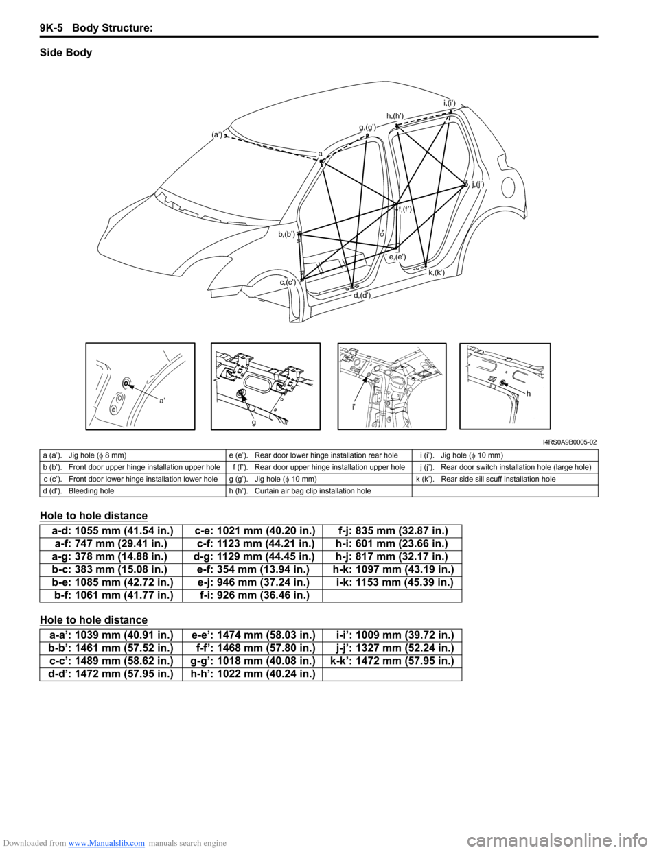
Side Body
Hole to hole distance
Hole to hole distance
I4RS0A9B0005-02
a (a’). Jig hole (φ 8 mm) e (e’). Rear door lower hinge installation rear hole i (i’). Jig hole ( φ 10 mm)
b (b’). Front door upper hinge installation upper hole f (f’). Rear door upper hinge installation upper hole j (j’). Rear door switc h installation hole (large hole)
c (c’). Front door lower hinge installation lower hole g (g’). Jig hole ( φ 10 mm) k (k’). Rear side sill scuff installation hole
d (d’). Bleeding hole h (h’). Curtain air bag clip installation hole
a-d: 1055 mm (41.54 in.) c-e: 1021 mm (40.20 in.) f-j: 835 mm (32.87 in.) a-f: 747 mm (29.41 in.) c-f: 1123 mm (44.21 in.) h-i: 601 mm (23.66 in.)
a-g: 378 mm (14.88 in.) d-g: 1129 mm (44.45 in.) h-j: 817 mm (32.17 in.)
b-c: 383 mm (15.08 in.) e-f: 354 mm (13.94 in.) h-k: 1097 mm (43.19 in.)
b-e: 1085 mm (42.72 in.) e-j: 946 mm (37.24 in.) i-k: 1153 mm (45.39 in.) b-f: 1061 mm (41.77 in.) f-i: 926 mm (36.46 in.)
a-a’: 1039 mm (40.91 in.) e-e’: 1474 mm (58.03 in.) i-i’: 1009 mm (39.72 in.)
b-b’: 1461 mm (57.52 in.) f-f’: 1468 mm (57.80 in.) j-j’: 1327 mm (52.24 in.) c-c’: 1489 mm (58.62 in.) g-g’: 1018 mm (40.08 in.) k-k’: 1472 mm (57.95 in.)
d-d’: 1472 mm (57.95 in.) h-h’: 1022 mm (40.24 in.)
Page 1383 of 1496
Downloaded from www.Manualslib.com manuals search engine Body Structure: 9K-6
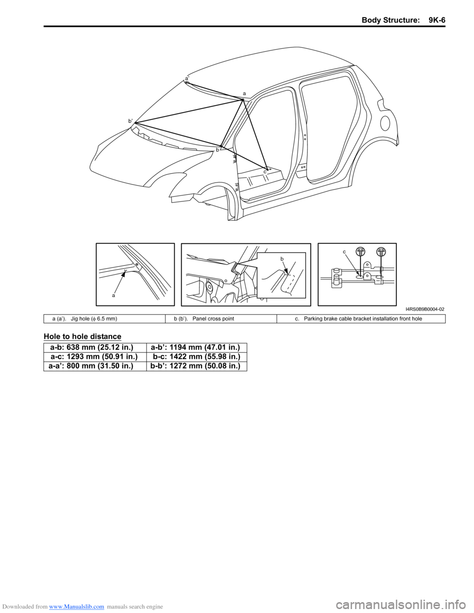
Hole to hole distance
a
cb
a’
a
bc
b’
I4RS0B9B0004-02
a (a’). Jig hole (φ 6.5 mm) b (b’). Panel cross point c. Parking brake cable bracket installation front hole
a-b: 638 mm (25.12 in.) a-b’: 1194 mm (47.01 in.)
a-c: 1293 mm (50.91 in.) b-c: 1422 mm (55.98 in.)
a-a’: 800 mm (31.50 in.) b-b’: 1272 mm (50.08 in.)
Page 1384 of 1496
Downloaded from www.Manualslib.com manuals search engine 9K-7 Body Structure:
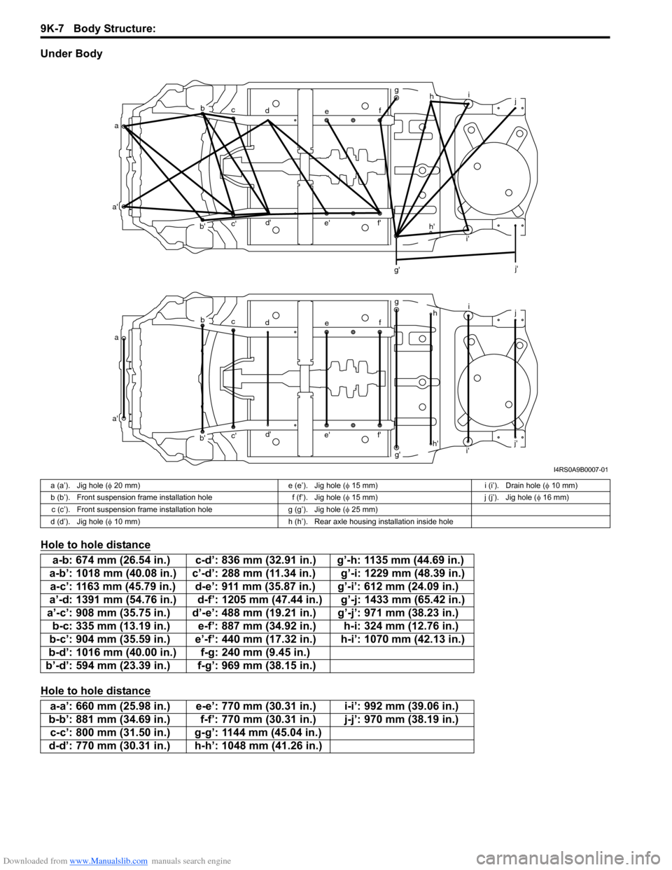
Under Body
Hole to hole distance
Hole to hole distance
ab
c d e fg
h i
j
a' b'c'
d'
e' f'
g' i'
j'
a b
c d e fg
hi
j
a' b'c'
d'
e' f'
g'h'
i' j'
h'
I4RS0A9B0007-01
a (a’). Jig hole (
φ 20 mm) e (e’). Jig hole ( φ 15 mm) i (i’). Drain hole ( φ 10 mm)
b (b’). Front suspension frame installation hole f (f’). Jig hole ( φ 15 mm) j (j’). Jig hole ( φ 16 mm)
c (c’). Front suspension frame installation hole g (g’). Jig hole (φ 25 mm)
d (d’). Jig hole ( φ 10 mm) h (h’). Rear axle housing installation inside hole
a-b: 674 mm (26.54 in.) c-d’: 836 mm (32.91 in.) g’-h: 1135 mm (44.69 in.)
a-b’: 1018 mm (40.08 in.) c’-d’: 288 mm (11.34 in.) g’-i: 1229 mm (48.39 in.) a-c’: 1163 mm (45.79 in.) d-e’: 911 mm (35.87 in.) g’-i’: 612 mm (24.09 in.)
a’-d: 1391 mm (54.76 in.) d-f’: 1205 mm (47.44 in.) g’-j: 1433 mm (65.42 in.)
a’-c’: 908 mm (35.75 in.) d’-e’: 488 mm (1 9.21 in.) g’-j’: 971 mm (38.23 in.)
b-c: 335 mm (13.19 in.) e-f’: 887 mm (34.92 in.) h-i: 324 mm (12.76 in.)
b-c’: 904 mm (35.59 in.) e’-f’: 440 mm (17.32 in.) h-i’: 1070 mm (42.13 in.)
b-d’: 1016 mm (40.00 in.) f-g: 240 mm (9.45 in.)
b’-d’: 594 mm (23.39 in.) f-g’: 969 mm (38.15 in.)
a-a’: 660 mm (25.98 in.) e-e’: 770 mm (30.31 in.) i-i’: 992 mm (39.06 in.)
b-b’: 881 mm (34.69 in.) f-f’: 770 mm (30.31 in.) j-j’: 970 mm (38.19 in.) c-c’: 800 mm (31.50 in.) g-g’: 1144 mm (45.04 in.)
d-d’: 770 mm (30.31 in.) h-h’: 1048 mm (41.26 in.)
Page 1385 of 1496
Downloaded from www.Manualslib.com manuals search engine Body Structure: 9K-8
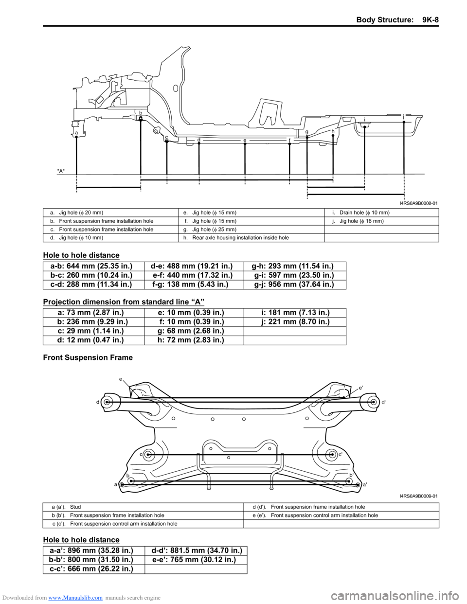
Hole to hole distance
Projection dimension from standard line “A”
Front Suspension Frame
Hole to hole distance
i
g
f
e
d
c
ab
"A"j
h
I4RS0A9B0008-01
a. Jig hole ( φ 20 mm) e. Jig hole ( φ 15 mm) i. Drain hole ( φ 10 mm)
b. Front suspension frame installation hole f. Jig hole (φ 15 mm) j. Jig hole (φ 16 mm)
c. Front suspension frame installation hole g. Jig hole ( φ 25 mm)
d. Jig hole ( φ 10 mm) h. Rear axle housing installation inside hole
a-b: 644 mm (25.35 in.) d-e: 488 mm (19.21 in.) g-h: 293 mm (11.54 in.)
b-c: 260 mm (10.24 in.) e-f: 440 mm (17.32 in.) g-i: 597 mm (23.50 in.)
c-d: 288 mm (11.34 in.) f-g: 138 mm (5.43 in.) g-j: 956 mm (37.64 in.)
a: 73 mm (2.87 in.) e: 10 mm (0.39 in.) i: 181 mm (7.13 in.)
b: 236 mm (9.29 in.) f: 10 mm (0.39 in.) j: 221 mm (8.70 in.) c: 29 mm (1.14 in.) g: 68 mm (2.68 in.)
d: 12 mm (0.47 in.) h: 72 mm (2.83 in.)
a b c
d
e
a'
b'
c' d'
e'
I4RS0A9B0009-01
a (a’). Stud
d (d’). Front suspension frame installation hole
b (b’). Front suspension frame installation hole e (e’). Front suspension control arm installation hole
c (c’). Front suspension control arm installation hole
a-a’: 896 mm (35.28 in.) d-d’: 881.5 mm (34.70 in.)
b-b’: 800 mm (31.50 in.) e-e’: 765 mm (30.12 in.) c-c’: 666 mm (26.22 in.)
Page 1386 of 1496
Downloaded from www.Manualslib.com manuals search engine 9K-9 Body Structure:
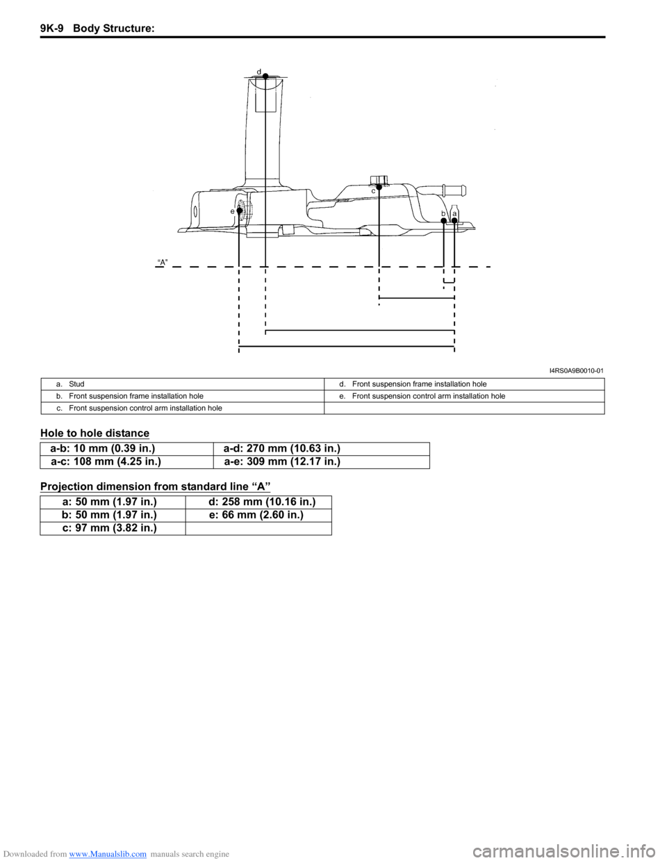
Hole to hole distance
Projection dimension from standard line “A”
I4RS0A9B0010-01
a. Studd. Front suspension frame installation hole
b. Front suspension frame installation hole e. Front suspension control arm installation hole
c. Front suspension control arm installation hole
a-b: 10 mm (0.39 in.) a-d: 270 mm (10.63 in.)
a-c: 108 mm (4.25 in.) a-e: 309 mm (12.17 in.)
a: 50 mm (1.97 in.) d: 258 mm (10.16 in.)
b: 50 mm (1.97 in.) e: 66 mm (2.60 in.)
c: 97 mm (3.82 in.)
Page 1402 of 1496
Downloaded from www.Manualslib.com manuals search engine 10-ii Table of Contents
DTC P1615: ID Code Does Not Registered (Vehicle equipped with keyless start system
only) ................................................................10C-9
DTC P1616: Different Registration ID Codes (Vehicle equipped with keyless start system
only) ..............................................................10C-10
DTC P1618: CAN Communication Error (Reception Error for Keyless Start Control
Module) (Vehicle equipped with keyless
start system only) ..........................................10C-11
DTC P1621: Immobilizer Communication Line Error ......................................................10C-12
DTC P1622: EEPROM Reading / Writing Error ..............................................................10C-13
DTC P1623: Unregistered Transponder .........10C-13
DTC P1625: Immobilizer An tenna Error..........10C-14
DTC P1636: Immobilizer Information Registration Failure .......................................10C-14
DTC P1638: Immobilizer Information Mismatched ...................................................10C-15
Inspection of Immobilizer Control Module (ICM) and Its Circuit ....... ...............................10C-16
Repair Instructions ........... ...............................10C-18
Immobilizer Control Mo dule (ICM) Removal
and Installation ..............................................10C-18
Registration of the Ignition Key .......................10C-18
Procedure after ECM Replacement ................10C-18
Special Tools and Equipmen t .........................10C-19
Special Tool ....................................................10C-19
Keyless Start System ....... ......................10E-1
General Description ........................................... 10E-1
Keyless Start System Description ..................... 10E-1
Parts and Functions .......................................... 10E-2
Keyless Engine Start Function .......................... 10E-3
Door Lock Function of Keyless Start System .... 10E-4
Operation Area of Remote Controller................ 10E-5
Alarm Function .................................................. 10E-6
CAN Communication System Description......... 10E-6
Schematic and Routing Diagram ...................... 10E-7 Keyless Start System El ectric Wiring Circuit
Diagram .......................................................... 10E-7
Diagnostic Information and Procedures .......... 10E-8 Precautions in Diagnosing Troubles ................. 10E-8
Self-Diagnosis Function .................................... 10E-8
Keyless Start System Diagn osis Introduction ... 10E-8 Keyless Start System Chec
k ............................. 10E-8
Customer Questionnaire (E xample) .................. 10E-9
Key Indicator Lamp Check .............................. 10E-10
DTC Check...................................................... 10E-10
DTC Table ....................................................... 10E-11
DTC Clearance ............................................... 10E-12
Keyless Start System Symp tom Diagnosis ..... 10E-12
Keyless Start System Operation Inspection .... 10E-13
Door Lock Operation (Keyless Start System) . 10E-14
Inspection of Keyless Start Control Module and Its Circuits .............................................. 10E-14
No DTC Detection After Performing DTC Check ............................................................ 10E-18
Key Indicator Lamp Circuit Check (Key indicator lamp doesn’t light when ignition
knob switch is pushed.) ................................. 10E-20
Keyless Start Control Module Power and Ground Circuit Check .................................... 10E-22
DTC No. 11: Communi cation Error with
Steering Lock Unit ......................................... 10E-23
DTC No. 13 / No. 14: Release Signal Error from Steering Lock Unit / Steering Lock Unit
Malfunction .................................................... 10E-24
DTC No. 21 / No. 22: Internal Error of Keyless Start Control Module (EEPROM reading
error) / (EEPROM writing error) ............ ........ 10E-24
DTC No. 31: Lost Commun ication with BCM .. 10E-25
DTC No. 33: Control Module Communication
Bus Off .......................................................... 10E-27
DTC No. 51 / No. 52 / No. 53: Driver Side / Passenger Side / Rear End Door Request
Switch Failure................................................ 10E-28
Repair Instructions ............ .............................. 10E-30
Antennas and Request Switches Removal and Installation .............................................. 10E-30
Front Door (Driver and Passenger Side), Rear End Door Request Switch Inspection............ 10E-31
Steering Lock Unit Removal and Installation .. 10E-31
Steering Lock Unit Inspection ......................... 10E-31
Front Door Lock Switch In spection ................. 10E-31
Keyless Start Control Module Removal and Installation ..................................................... 10E-32
Remote Controller Inspection.......................... 10E-32
Replacement of Remote Controller Battery .... 10E-32
Registration Procedure for Remote Controller
ID Code ......................................................... 10E-33
Page 1414 of 1496
Downloaded from www.Manualslib.com manuals search engine 10B-11 Body Electrical Control System:
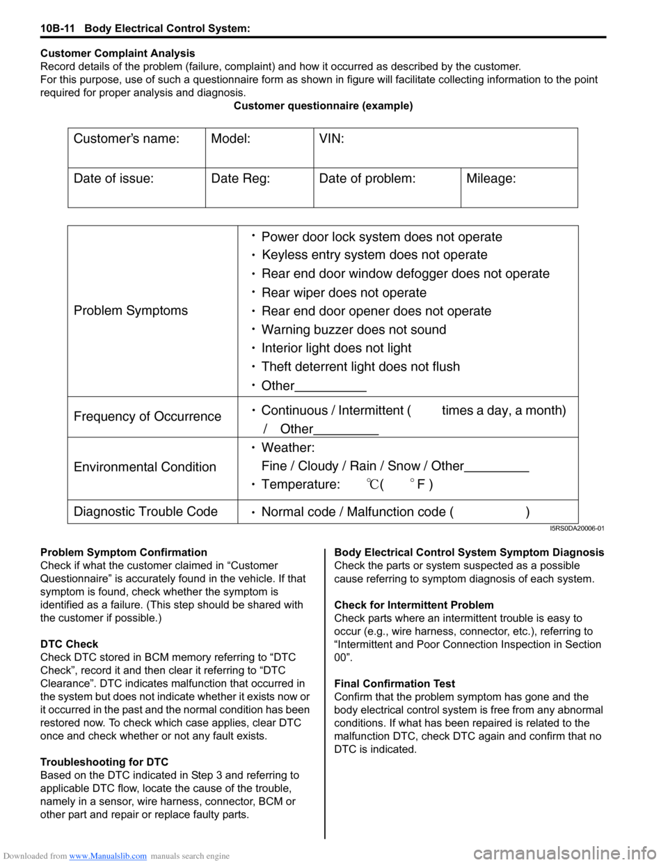
Customer Complaint Analysis
Record details of the problem (failure, complaint) and how it occurred as described by the customer.
For this purpose, use of such a questionnaire form as shown in figure will facilitate collectin g information to the point
required for proper analysis and diagnosis. Customer questionnaire (example)
Problem Symptom Confirmation
Check if what the custom er claimed in “Customer
Questionnaire” is accurately f ound in the vehicle. If that
symptom is found, check whether the symptom is
identified as a failure. (This step should be shared with
the customer if possible.)
DTC Check
Check DTC stored in BCM me mory referring to “DTC
Check”, record it and then clear it referring to “DTC
Clearance”. DTC indicates malfunction that occurred in
the system but does not indicate whether it exists now or
it occurred in the past and the normal condition has been
restored now. To check which case applies, clear DTC
once and check whether or not any fault exists.
Troubleshooting for DTC
Based on the DTC indicated in Step 3 and referring to
applicable DTC flow, locate the cause of the trouble,
namely in a sensor, wire harness, connector, BCM or
other part and repair or replace faulty parts. Body Electrical Control System Symptom Diagnosis
Check the parts or system
suspected as a possible
cause referring to symptom diagnosis of each system.
Check for Intermi ttent Problem
Check parts where an intermit tent trouble is easy to
occur (e.g., wire harness, connector, etc.), referring to
“Intermittent and Poor Connec tion Inspection in Section
00”.
Final Confirmation Test
Confirm that the problem symptom has gone and the
body electrical control system is free from any abnormal
conditions. If what has been repaired is related to the
malfunction DTC, check DTC again and confirm that no
DTC is indicated.
Customers name:
Model:
VIN:
Date of issue:
Date Reg:
Date of problem:
Mileage:
Problem Symptoms
Power door lock system does not operate
Keyless entry system does not operate
Rear end door window defogger does not operate
Rear wiper does not operate
Rear end door opener does not operate
Other
Frequency of Occurrence
Continuous / Intermittent ( times a day, a month)
/ Other
Environmental Condition
Weather:
Fine / Cloudy / Rain / Snow / Other
Temperature: (F )
Diagnostic Trouble Code Normal code / Malfunction code ( )
Warning buzzer does not sound
Interior light does not light
Theft deterrent light does not flush
I5RS0DA20006-01
Page 1423 of 1496
Downloaded from www.Manualslib.com manuals search engine Body Electrical Control System: 10B-20
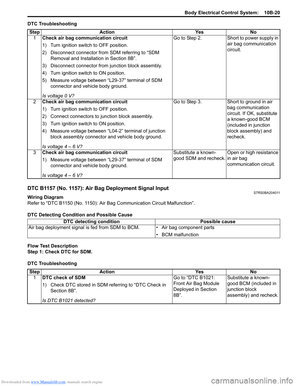
DTC Troubleshooting
DTC B1157 (No. 1157): Air Bag Deployment Signal InputS7RS0BA204011
Wiring Diagram
Refer to “DTC B1150 (No. 1150): Air Bag Communication Circuit Malfunction”.
DTC Detecting Conditi on and Possible Cause
Flow Test Description
Step 1: Check DTC for SDM.
DTC Troubleshooting Step Action Yes No
1 Check air bag communication circuit
1) Turn ignition switch to OFF position.
2) Disconnect connector from SDM referring to “SDM
Removal and Installation in Section 8B”.
3) Disconnect connector from junction block assembly.
4) Turn ignition switch to ON position.
5) Measure voltage between “L29-37” terminal of SDM connector and vehicle body ground.
Is voltage 0 V? Go to Step 2. Short to power supply in
air bag communication
circuit.
2 Check air bag communication circuit
1) Turn ignition switch to OFF position.
2) Connect connectors to junction block assembly.
3) Turn ignition switch to ON position.
4) Measure voltage between “L04-2” terminal of junction
block assembly connector and vehicle body ground.
Is voltage 4 – 6 V? Go to Step 3.
Short to ground in air
bag communication
circuit. If OK, substitute
a known-good BCM
(included in junction
block assembly) and
recheck.
3 Check air bag communication circuit
1) Measure voltage between “L29-37” terminal of SDM
connector and vehicle body ground.
Is voltage 4 – 6 V? Substitute a known-
good SDM and recheck.
Open or high resistance
in air bag
communication circuit.
DTC detecting condition
Possible cause
Air bag deployment signal is fed from SDM to BCM. • Air bag component parts
• BCM malfunction
StepAction YesNo
1 DTC check of SDM
1) Check DTC stored in SDM re ferring to “DTC Check in
Section 8B”.
Is DTC B1021 detected? Go to “DTC B1021:
Front Air Bag Module
Deployed in Section
8B”.
Substitute a known-
good BCM (included in
junction block
assembly) and recheck.