2006 SUZUKI SWIFT Information
[x] Cancel search: InformationPage 1011 of 1496
Downloaded from www.Manualslib.com manuals search engine Air Conditioning System: Automatic Type 7B-63
DTC B1546: A/C Refrigerant Pressure MalfunctionS7RS0B7224018
DTC Detecting Condition and Trouble Area
DTC Troubleshooting
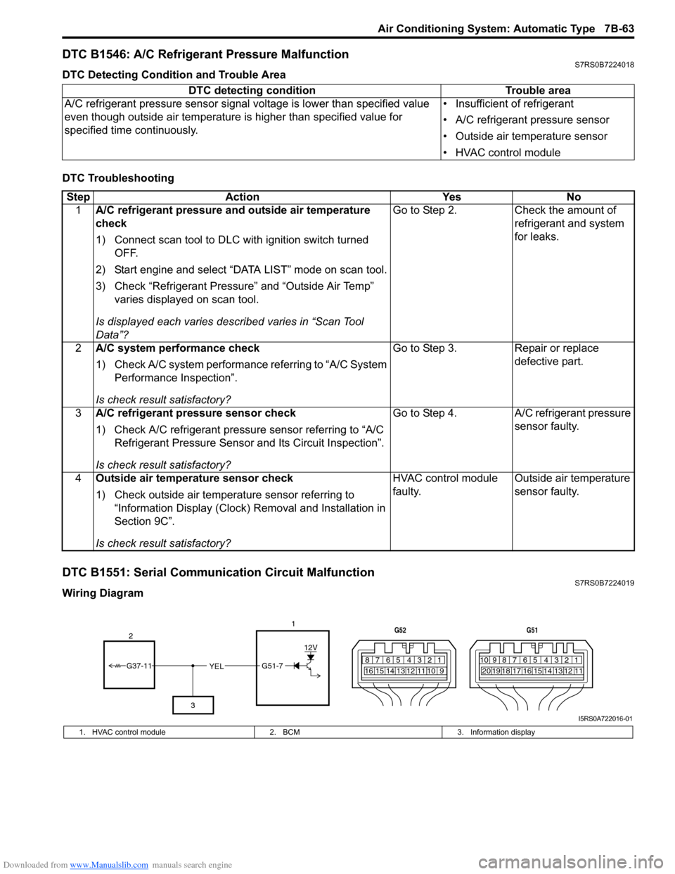
DTC B1551: Serial Communication Circuit MalfunctionS7RS0B7224019
Wiring DiagramDTC detecting condition Trouble area
A/C refrigerant pressure sensor signal voltage is lower t han specified value
even though outside air temperature is higher than specified value for
specified time continuously. • Insufficient of refrigerant
• A/C refrigerant pressure sensor
• Outside air temperature sensor
• HVAC control module
Step
Action YesNo
1 A/C refrigerant pressure and outside air temperature
check
1) Connect scan tool to DLC with ignition switch turned
OFF.
2) Start engine and select “DATA LIST” mode on scan tool.
3) Check “Refrigerant Pressure” and “Outside Air Temp” varies displayed on scan tool.
Is displayed each va ries described varies in “Scan Tool
Data”? Go to Step 2.
Check the amount of
refrigerant and system
for leaks.
2 A/C system performance check
1) Check A/C system performance referring to “A/C System
Performance Inspection”.
Is check result satisfactory? Go to Step 3.
Repair or replace
defective part.
3 A/C refrigerant pressure sensor check
1) Check A/C refrigerant pressure sensor referring to “A/C
Refrigerant Pressure Sensor and Its Circuit Inspection”.
Is check result satisfactory? Go to Step 4.
A/C refrigerant pressure
sensor faulty.
4 Outside air temperature sensor check
1) Check outside air temperature sensor referring to
“Information Display (Clock) Removal and Installation in
Section 9C”.
Is check result satisfactory? HVAC control module
faulty.
Outside air temperature
sensor faulty.
YEL17812910
65 431516 14 13 12 11
G52
789101920121112
65 431718 16 15 14 13
G51
G51-7
12V
2
3
G37-11
I5RS0A722016-01
1. HVAC control module 2. BCM3. Information display
Page 1012 of 1496
Downloaded from www.Manualslib.com manuals search engine 7B-64 Air Conditioning System: Automatic Type
DTC Detecting Condition and Trouble Area
DTC Troubleshooting
DTC B1552: Serial Communication Signal MalfunctionS7RS0B7224020
DTC Detecting Condition and Trouble AreaDTC detecting condition Trouble area
Serial communication signal is higher than or lower than specified value for
specified time continuously. • Serial communication line of BCM
• BCM (included in junction block
assembly)
• Information display
• HVAC control module
Step Action YesNo
1 DTC check
1) Connect scan tool to DLC with ignition switch turned
OFF.
2) Disconnect connector from information display.
3) Turn ignition switch ON and check DTC.
Is there DTC B1551? Go to Step 2.
Information display
faulty.
2 Wire harness check
1) Disconnect connectors from BCM and HVAC control
module.
2) Measure resistance between “G37-11” terminal of BCM connector and “G51-7” terminal of HVAC control module
connector.
Is resistance below 5
Ω? Go to Step 3. “YEL” wire open or high
resistance circuit.
3 Wire harness check
1) Measure resistance between “G51-7” terminal of HVAC
control module connector and vehicle body ground.
Is resistance infinity? Go to Step 4. “YEL” wire shorted to
ground circuit.
4 Wire harness check
1) Measure voltage between “G51-7” terminal of HVAC
control module connector and vehicle body ground with
ignition switch turned ON.
Is voltage 0 V? Go to Step 5. “YEL” wire shorted to
other circuit.
5 Serial communication signal check
1) Connect connectors to BCM and HVAC control module.
2) Using oscilloscope, check that serial communication
signal is outputted referring to “Reference waveform
No.8” of “Inspection of BCM and its Circuits in Section
10B”.
Is serial communication signal outputted at “G37-11”
terminal of BCM connector? HVAC control module
faulty.
BCM (included in
junction block
assembly) faulty.
DTC detecting condition
Trouble area
Data received by HVAC control module from BCM is erroneous continuously. • BCM (included in junction block assembly)
• HVAC control module
Page 1025 of 1496
Downloaded from www.Manualslib.com manuals search engine Air Conditioning System: Automatic Type 7B-77
HVAC Control Module Removal and InstallationS7RS0B7226013
Removal1) Disconnect negative (–) cable at battery.
2) Disable air bag system referring to “Disabling Air Bag System in Section 8B”.
3) Remove passenger air bag module from instrument panel referring to “Passenger Air Bag (Inflator)
Module Removal and Installation in Section 8B”.
4) Remove radio assembly from instrument panel referring to “Rear Speaker Removal and Installation
in Section 9C”.
5) Remove two connectors fr om HVAC control module.
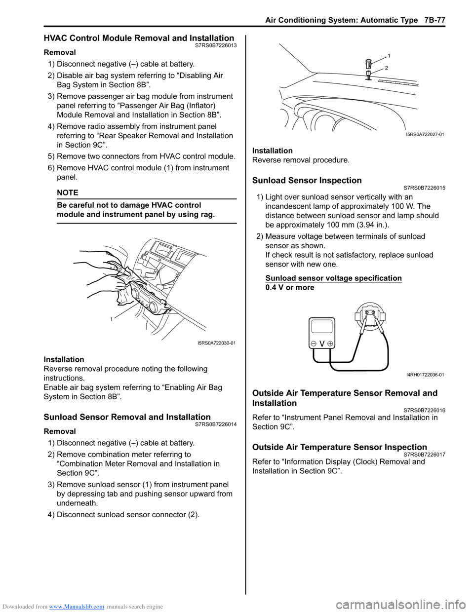
6) Remove HVAC control modu le (1) from instrument
panel.
NOTE
Be careful not to damage HVAC control
module and instrument panel by using rag.
Installation
Reverse removal procedure noting the following
instructions.
Enable air bag system referring to “Enabling Air Bag
System in Section 8B”.
Sunload Sensor Removal and InstallationS7RS0B7226014
Removal
1) Disconnect negative (–) cable at battery.
2) Remove combination meter referring to “Combination Meter Removal and Installation in
Section 9C”.
3) Remove sunload sensor (1) from instrument panel by depressing tab and pushing sensor upward from
underneath.
4) Disconnect sunload sensor connector (2). Installation
Reverse removal procedure.
Sunload Sensor InspectionS7RS0B7226015
1) Light over sunload sensor vertically with an
incandescent lamp of approximately 100 W. The
distance between sunload sensor and lamp should
be approximately 100 mm (3.94 in.).
2) Measure voltage between terminals of sunload sensor as shown.
If check result is not satisfactory, replace sunload
sensor with new one.
Sunload sensor voltage specification
0.4 V or more
Outside Air Temperature Sensor Removal and
Installation
S7RS0B7226016
Refer to “Instrument Panel Re moval and Installation in
Section 9C”.
Outside Air Temperature Sensor InspectionS7RS0B7226017
Refer to “Information Display (Clock) Removal and
Installation in Section 9C”.
1
I5RS0A722030-01
1
2
I5RS0A722027-01
I4RH01722036-01
Page 1029 of 1496
Downloaded from www.Manualslib.com manuals search engine Table of Contents 8- i
8
Section 8
CONTENTS
Restraint
Precautions ................................................. 8-1
Precautions............................................................. 8-1
Precautions on Restraint ....................................... 8-1
Seat Belts .......... ............................... ........ 8A-1
Precautions........................................................... 8A-1
Precautions on Service a nd Diagnosis of Seat
Belt .................................................................... 8A-1
General Description ............................................. 8A-1 Seat Belt Construction ........................................ 8A-1
Diagnostic Information and Procedures ............ 8A-2 Repair and Inspection Required after Accident ............................................................ 8A-2
Repair Instructions .............................................. 8A-3 Front Seat Belt Components ............................... 8A-3
Front Seat Belt Removal and Installation ............ 8A-4
Front Seat Belt Inspection ................................... 8A-4
Rear Seat Belt Components ............................... 8A-6
Rear Seat Belt Removal and Installation ............ 8A-7
Rear Seat Belt Inspection ................................... 8A-7
Specifications ....................................................... 8A-7
Tightening Torque Specifications ........................ 8A-7
Air Bag System ............... ......................... 8B-1
Precautions........................................................... 8B-1
Precautions on Service and Diagnosis of Air Bag System....................................................... 8B-1
Precautions on Handling and Storage of Air Bag System Components . ................................ 8B-2
Precautions on Disposal of Air Bag and Seat
Belt Pretensioner .............................................. 8B-5
General Description ............................................. 8B-5 Air Bag System Construction .............................. 8B-5
Air Bag System Input / Output Table .................. 8B-6
Schematic and Routing Diagram ........................ 8B-7 Air Bag System Wiring Circuit Diagram .............. 8B-7
Component Locatio n ........................................... 8B-9
Air Bag System Components, Wiring and Connectors Location ......................................... 8B-9
Diagnostic Information and Procedures .......... 8B-10 Air Bag Diagnostic System Check .................... 8B-10
Air Bag Diagnostic System Check Flow ............ 8B-10
DTC Table ......................................................... 8B-11
DTC Check ....................................................... 8B-12 DTC Clearance ................................................. 8B-12
Scan Tool Data ................................................. 8B-13
“AIR BAG” Warning Right Comes ON Steady .. 8B-13
“AIR BAG” Warning Right Does Not Come
ON ................................................................... 8B-15
“AIR BAG” Warning Right Flashes .................... 8B-16
DTC B1013: SDM fault...................................... 8B-17
DTC B1014: “AIR BAG” Warning Right Circuit Failure ............................................................. 8B-17
DTC B1016: Power Source Voltage High ......... 8B-18
DTC B1017: Power Source Voltage Low .......... 8B-20
DTC B1021: Front Air Bag Module Deployed ... 8B-22
DTC B1024 / B1025: Side-Air Bag (Driver / Passenger) Deployed...................................... 8B-22
DTC B1026: Pretensioner Activated ................. 8B-23
DTC B1027: Reusable Number Exceeded ....... 8B-24
DTC B1031: Driver Air Bag Initiator Circuit
Resistance High .............................................. 8B-24
DTC B1032: Driver Air Bag Initiator Circuit
Resistance Low ............................................... 8B-29
DTC B1033: Driver Air Bag Initiator Circuit
Short to Ground............................................... 8B-34
DTC B1034: Driver Air Bag Initiator Circuit
Short to Power Circuit .... ................................. 8B-39
DTC B1041: Passenger Air Bag Initiator Circuit Resistance High ................................... 8B-44
DTC B1042: Passenger Air Bag Initiator Circuit Resistance Low.................................... 8B-47
DTC B1043: Passenger Air Bag Initiator Circuit Short to Ground ................................... 8B-50
DTC B1044: Passenger Air Bag Initiator Circuit Short to Power Circ uit .......................... 8B-53
DTC B1051 / B1055: Driver / Passenger Pretensioner Initiator Circuit Resistance
High ................................................................. 8B-56
DTC B1052 / B1056: Driver / Passenger Pretensioner Initiator Circu it Resistance Low .. 8B-58
DTC B1053 / B1057: Driver / Passenger Pretensioner Initiator Circuit Short to Ground .. 8B-60
DTC B1054 / B1058: Driver / Passenger Pretensioner Initiator Circuit Short to Power
Circuit .............................................................. 8B-62
DTC B1061 / B1065: Driver / Passenger Side- Air Bag Initiator Circuit Resistance High ......... 8B-64
Page 1033 of 1496
Downloaded from www.Manualslib.com manuals search engine Seat Belts: 8A-2
Seat Belt with ELR
The seat belt with emergency locking retractor (ELR) is
designed so that it locks immediately (to prevent the
webbing from being pulled out of the retractor any
further) when any of the following items is detected as
exceeding each set value;
• Speed at which the webbing is pulled out of the retractor.
• Acceleration or deceleration of the vehicle speed.
• Inclination.
Seat Belt with A-ELR
The automatic and emergency locking retractor (A-ELR)
works as an Emergency Locking Retractor (ELR) till its
webbing is pulled all the way out and then on as an
Automatic Locking Retractor (ALR ) till it is retracted fully.
ALR: Automatically locks when the webbing is pulled out
from the retractor and allowed to retract even a little.
Then the webbing can not be pulled out any further,
unless it is wound all the way back into the retractor,
which releases the lock and allows the webbing to be
pulled out.
Seat Belt with ELR and Pretensioner
The seat belt with ELR and a pretensioner has a
pretensioner mechanism whic h operates in linkage with
the air bag in addition to the described ELR.
The pretensioner is incorporated in retractor assembly
and controlled by SDM as one of air bag system
components. It will be activated at the same time as the
driver and passenger air bag module when an impact at
the front of vehicle exceeds the specified value.
When servicing seat belt (retractor assembly) with
pretensioner, be sure to observe all WARNINGS and
CAUTIONS and “Precautions on Service and Diagnosis
of Air Bag System in Section 8B”. CAUTION!
Do not reuse the seat belt pretensioner
(retractor assembly) that has activated.
Replace it with a new seat belt assembly and
buckle together as a set. For checking
procedure of its activation, refer to “Repair
and Inspection Required after Accident in
Section 8B”.
Seat Belt Remainder
When driver’s seat belt is unfastened (under the
following conditions), seat belt reminder light and
warning buzzer inform that driver’s seat belt is
unfastened. Seat belt reminder light located in
combination meter and warning buzzer located inside
BCM operate as follows:
• Seat belt reminder light comes on when driver’s seat belt is unfastened while igni tion key switch is at ON
position.
• If vehicle speed exceeds 15 km/h with seat belt unfastened, warning buzzer operates for
approximately 95 seconds and seat belt reminder light
flashes synchronously with buzzer. When warning
buzzer stops operating, seat belt reminder light is
turned on.
• If driver’s seat belt state is changed from “fastened” to “unfastened” while vehicle speed is above 15 km/h,
warning buzzer operates for approximately 95
seconds and seat belt reminder light flashes
synchronously with buzzer. When warning buzzer
stops operating, seat belt reminder light is turned on.
Diagnostic Information and Procedures
Repair and Inspection Required after AccidentS7RS0B8104001
After an accident, whether the seat belt pretensioner has been activated or not, be sure to perform checks and repairs
described on “Repair and Inspection Required after Accident in Section 8B”.
Page 1038 of 1496
Downloaded from www.Manualslib.com manuals search engine 8A-7 Seat Belts:
Rear Seat Belt Removal and InstallationS7RS0B8106005
WARNING!
Be sure to read “Precautions on Service and
Diagnosis of Seat Belt” before starting to
work and observe every precaution during
work.
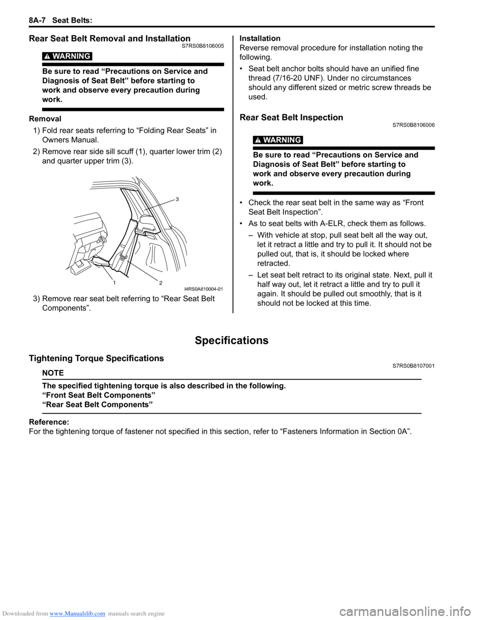
Removal1) Fold rear seats referring to “Folding Rear Seats” in Owners Manual.
2) Remove rear side sill scuff (1), quarter lower trim (2)
and quarter upper trim (3).
3) Remove rear seat belt referring to “Rear Seat Belt Components”. Installation
Reverse removal procedure for installation noting the
following.
• Seat belt anchor bolts should have an unified fine
thread (7/16-20 UNF). Under no circumstances
should any different sized or metric screw threads be
used.Rear Seat Belt InspectionS7RS0B8106006
WARNING!
Be sure to read “Precautions on Service and
Diagnosis of Seat Belt” before starting to
work and observe every precaution during
work.
• Check the rear seat belt in the same way as “Front Seat Belt Inspection”.
• As to seat belts with A-ELR, check them as follows. – With vehicle at stop, pull seat belt all the way out, let it retract a little and try to pull it. It should not be
pulled out, that is, it should be locked where
retracted.
– Let seat belt retract to its original state. Next, pull it
half way out, let it retrac t a little and try to pull it
again. It should be pulled out smoothly, that is it
should not be locked at this time.
Specifications
Tightening Torque SpecificationsS7RS0B8107001
NOTE
The specified tightening torque is also described in the following.
“Front Seat Belt Components”
“Rear Seat Belt Components”
Reference:
For the tightening torque of fastener not specified in this section, refer to “Fasteners Information in Section 0A”.
3
2
1
I4RS0A810004-01
Page 1048 of 1496
Downloaded from www.Manualslib.com manuals search engine 8B-10 Air Bag System:
Diagnostic Information and Procedures
Air Bag Diagnostic System CheckS7RS0B8204001
WARNING!
To avoid deployment when troubleshooting
the air bag system, do not use electrical test
equipment such as a battery powered or AC
powered voltmeter, ohmmeter, etc., or any
type of electrical equipment other than that
specified in this manual. Do not use a non-
powered probe type tester.
Instructions in this manual must be followed
carefully, otherwise personal injury may
result.
CAUTION!
The order in which DTCs are diagnosed is
very important. Failure to diagnose the DTCs
in the order specified may result in extended
diagnostic time, incorrect diagnosis and
incorrect parts replacement.
The diagnostic procedures used are designed to find
and repair air bag system malfunctions.
To get the best results, it is important to use the
diagnostic flow and follow the sequence in the following.1) Perform the “Air Bag Diagnostic System Check Flow”.
(The “Air Bag Diagnostic System Check Flow” must
be the starting point of any air bag system diagnosis.
The “Air Bag Diagnostic System Check Flow” checks
for proper “AIR BAG” warning right operation
through “AIR BAG” warning right and whether air
bag DTCs exist.)
2) Refer to the proper diagnost ic flow as directed by the
“Air Bag Diagnostic System Check Flow”.
(The “Air Bag Diagnostic System Check Flow” will
lead you to the correct flow to diagnose any air bag
system malfunctions. Bypassing these procedures
may result in extended diagnostic time, incorrect
diagnosis and incorrect parts replacement.)
3) Repeat the “Air Bag Diagnostic System Check Flow” after any repair or diagnostic procedures have been
performed.
(Performing the “Air Bag Diagnostic System Check
Flow” after all repair or diagnostic procedures will
ensure that the repair has been made correctly and
that no other malfunctions exist.)
Air Bag Diagnostic System Check FlowS7RS0B8204002
Flow test description
Step 1: Check that “AIR BAG” warning right lights.
Step 2: Check that “AIR BAG” warning right lights.
Step 3: Check that “AIR BAG” warning right flas hes 6 times after ignition switch is turned ON.
Step 4: Check that history codes are in SDM memory.
Step 5: Check that current code is in SDM memory.
6. “A/BAG” fuse in junction block assembly (including BCM) 13. Side curtain-air bag (inflator) module (if equipped)
7. Air bag harness in floor harness 14. Air bag harness in instrument panel harness
Step Action YesNo
1 1) Make sure that battery voltage is about 11 V or higher.
2) Note “AIR BAG” warning right as ignition switch is turned
ON.
Does “AIR BAG” warning ri ght come ON when ignition
switch is turned ON? Go to Step 2.
Proceed to ““AIR BAG”
Warning Right Does Not
Come ON”.
2 Does “AIR BAG” warning right come ON steady? Proceed to ““AIR BAG”
Warning Right Comes
ON Steady”.Go to Step 3.
3 Does “AIR BAG” warning right turn OFF, after flashing 6
times? “AIR BAG” warning right
circuit is in good
condition. Go to Step 4.“AIR BAG” warning right
circuit is in good
condition. Go to Step 5.
Page 1163 of 1496
Downloaded from www.Manualslib.com manuals search engine Air Bag System: 8B-125
Specifications
Tightening Torque SpecificationsS7RS0B8207001
NOTE
The specified tightening torque is also described in the following.
“Air Bag System Components, Wiring and Connectors Location”
Reference:
For the tightening torque of fastener not specified in this section, refer to “Fasteners Information in Section 0A”.
Special Tools and Equipment
Use of Special ToolsS7RS0B8208001
WARNING!
To avoid deployment when troubleshooting
the air bag system, do not use electrical test
equipment such as a battery powered or AC
powered voltmeter, ohmmeter, etc., or any
type of electrical equipment other than that
specified. Do not use a non-powered probe
type tester.
Instructions must be followed carefully,
otherwise personal injury may result.
You should be familiar with the tools listed under the
heading “Special Tool”. You should be able to measure
voltage and resistance. You should be familiar with
proper use of a scan tool such as Air Bag Driver /
Passenger Load Tool, Connector Test Adapter Kit and
the Digital Multimeter.
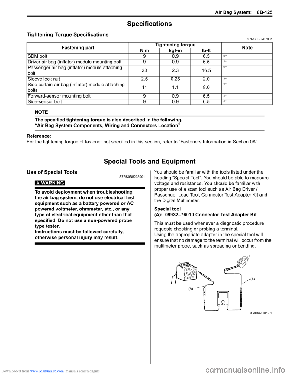
Special tool
(A): 09932–76010 Connector Test Adapter Kit
This must be used whenever a diagnostic procedure
requests checking or probing a terminal.
Using the appropriate adapter in the special tool will
ensure that no damage to the terminal will occur from the
multimeter probe, such as spreading or bending.
Fastening part
Tightening torque
Note
N ⋅mkgf-mlb-ft
SDM bolt 9 0.9 6.5 �)
Driver air bag (inflator) module mounting bolt 9 0.9 6.5 �)
Passenger air bag (inflator) module attaching
bolt 23 2.3 16.5�)
Sleeve lock nut 2.5 0.25 2.0 �)
Side curtain-air bag (inflator) module attaching
bolts 11 1.1 8.0�)
Forward-sensor mounting bolt 9 0.9 6.5 �)
Side-sensor bolt 9 0.9 6.5 �)
I3JA01820041-01