2006 SUZUKI SWIFT mounting nut
[x] Cancel search: mounting nutPage 482 of 1496
Downloaded from www.Manualslib.com manuals search engine 3A-4 Drive Shaft / Axle:
Front Drive Shaft Assembly On-Vehicle
Inspection
S7RS0B3106002
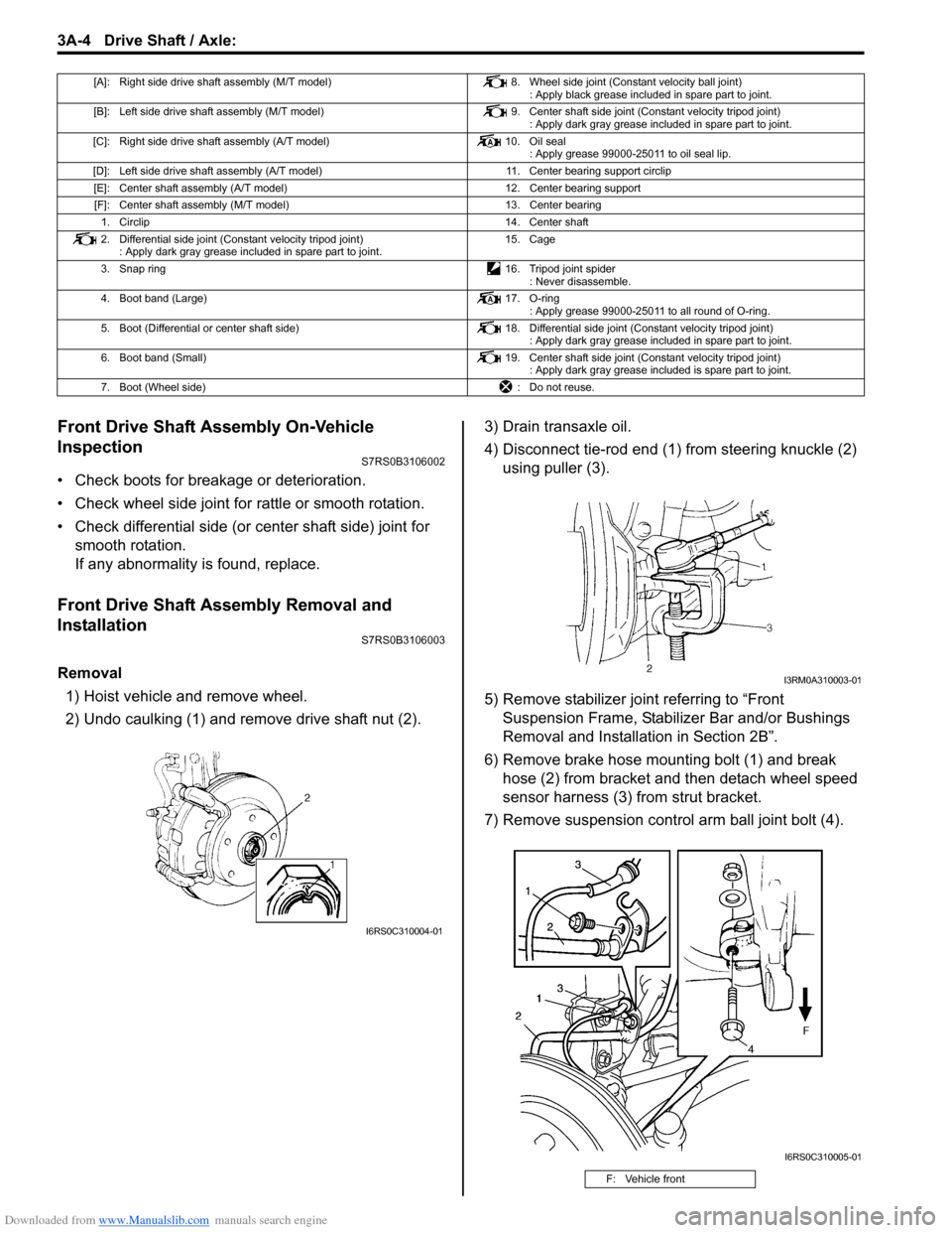
• Check boots for breakage or deterioration.
• Check wheel side joint for rattle or smooth rotation.
• Check differential side (or center shaft side) joint for smooth rotation.
If any abnormality is found, replace.
Front Drive Shaft Assembly Removal and
Installation
S7RS0B3106003
Removal
1) Hoist vehicle and remove wheel.
2) Undo caulking (1) and remove drive shaft nut (2). 3) Drain transaxle oil.
4) Disconnect tie-rod end (1) from steering knuckle (2)
using puller (3).
5) Remove stabilizer join t referring to “Front
Suspension Frame, Stabiliz er Bar and/or Bushings
Removal and Installati on in Section 2B”.
6) Remove brake hose mounting bolt (1) and break hose (2) from bracket and then detach wheel speed
sensor harness (3) from strut bracket.
7) Remove suspension contro l arm ball joint bolt (4).
[A]: Right side drive shaft assembly (M/T model) 8. Wheel side joint (Constant velocity ball joint)
: Apply black grease included in spare part to joint.
[B]: Left side drive shaft assembly (M/T model) 9. Center shaft side joint (Constant velocity tripod joint)
: Apply dark gray grease included in spare part to joint.
[C]: Right side drive shaft assembly (A/T model) 10. Oil seal
: Apply grease 99000-25011 to oil seal lip.
[D]: Left side drive shaft assembly (A/T model) 11. Center bearing support circlip
[E]: Center shaft assembly (A/T model) 12. Center bearing support
[F]: Center shaft assembly (M/T model) 13. Center bearing
1. Circlip 14. Center shaft
2. Differential side joint (Constant velocity tripod joint) : Apply dark gray grease included in spare part to joint. 15. Cage
3. Snap ring 16. Tripod joint spider
: Never disassemble.
4. Boot band (Large) 17. O-ring
: Apply grease 99000-25011 to all round of O-ring.
5. Boot (Differential or center shaft side) 18. Differential side joint (Constant velocity tripod joint)
: Apply dark gray grease included in spare part to joint.
6. Boot band (Small) 19. Center shaft side joint (Constant velocity tripod joint)
: Apply dark gray grease included is spare part to joint.
7. Boot (Wheel side) : Do not reuse.
I6RS0C310004-01
F: Vehicle front
I3RM0A310003-01
I6RS0C310005-01
Page 483 of 1496
Downloaded from www.Manualslib.com manuals search engine Drive Shaft / Axle: 3A-5
8) Disconnect front suspension control arm ball joint
stud from steering knuckle.
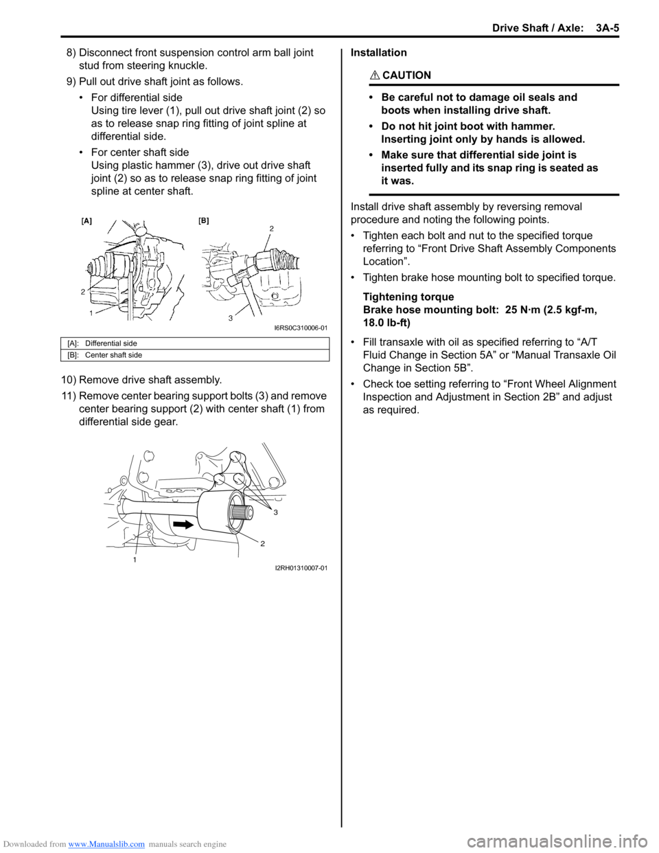
9) Pull out drive shaft joint as follows. • For differential sideUsing tire lever (1), pull out drive shaft joint (2) so
as to release snap ring fitting of joint spline at
differential side.
• For center shaft side Using plastic hammer (3), drive out drive shaft
joint (2) so as to release snap ring fitting of joint
spline at center shaft.
10) Remove drive shaft assembly. 11) Remove center bearing support bolts (3) and remove center bearing support (2) with center shaft (1) from
differential side gear. Installation
CAUTION!
• Be careful not to damage oil seals and
boots when installing drive shaft.
• Do not hit joint boot with hammer. Inserting joint only by hands is allowed.
• Make sure that differential side joint is inserted fully and its snap ring is seated as
it was.
Install drive shaft assemb ly by reversing removal
procedure and noting the following points.
• Tighten each bolt and nut to the specified torque referring to “Front Drive Shaft Assembly Components
Location”.
• Tighten brake hose mounting bolt to specified torque.
Tightening torque
Brake hose mounting bolt: 25 N·m (2.5 kgf-m,
18.0 lb-ft)
• Fill transaxle with oil as sp ecified referring to “A/T
Fluid Change in Section 5A” or “Manual Transaxle Oil
Change in Section 5B”.
• Check toe setting referring to “Front Wheel Alignment Inspection and Adjustment in Section 2B” and adjust
as required.
[A]: Differential side
[B]: Center shaft side
I6RS0C310006-01
3
2
1I2RH01310007-01
Page 515 of 1496
Downloaded from www.Manualslib.com manuals search engine Brake Control System and Diagnosis: 4A-17
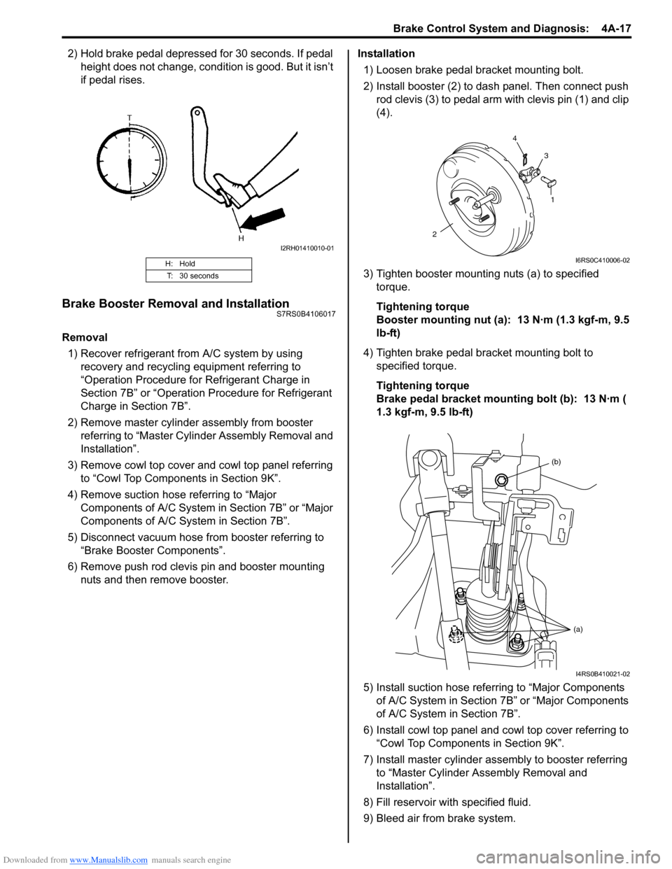
2) Hold brake pedal depressed for 30 seconds. If pedal height does not change, condition is good. But it isn’t
if pedal rises.
Brake Booster Removal and InstallationS7RS0B4106017
Removal
1) Recover refrigerant from A/C system by using recovery and recycling equipment referring to
“Operation Procedure for Refrigerant Charge in
Section 7B” or “Operation Procedure for Refrigerant
Charge in Section 7B”.
2) Remove master cylinder assembly from booster referring to “Master Cylin der Assembly Removal and
Installation”.
3) Remove cowl top cover and cowl top panel referring to “Cowl Top Components in Section 9K”.
4) Remove suction hose referring to “Major Components of A/C System in Section 7B” or “Major
Components of A/C System in Section 7B”.
5) Disconnect vacuum hose from booster referring to “Brake Booster Components”.
6) Remove push rod clevis pin and booster mounting nuts and then remove booster. Installation
1) Loosen brake pedal bracket mounting bolt.
2) Install booster (2) to dash panel. Then connect push rod clevis (3) to pedal arm with clevis pin (1) and clip
(4).
3) Tighten booster mounting nuts (a) to specified torque.
Tightening torque
Booster mounting nut (a): 13 N·m (1.3 kgf-m, 9.5
lb-ft)
4) Tighten brake pedal bracket mounting bolt to specified torque.
Tightening torque
Brake pedal bracket mounting bolt (b): 13 N·m (
1.3 kgf-m, 9.5 lb-ft)
5) Install suction hose referring to “Major Components of A/C System in Section 7B” or “Major Components
of A/C System in Section 7B”.
6) Install cowl top panel and cowl top cover referring to
“Cowl Top Components in Section 9K”.
7) Install master cylinder assembly to booster referring to “Master Cylinder Assembly Removal and
Installation”.
8) Fill reservoir with specified fluid.
9) Bleed air from brake system.
H: Hold
T: 30 seconds
I2RH01410010-01
1
2 4
3
I6RS0C410006-02
(b)
(a)
I4RS0B410021-02
Page 516 of 1496
Downloaded from www.Manualslib.com manuals search engine 4A-18 Brake Control System and Diagnosis:
10) Check pedal height and play referring to “Brake Pedal Free Height Inspection” and “Brake Pedal
Play Inspection”.
11) Check each installed part for fluid leakage and perform brake test.
12) Evacuate and charge refrigerant by referring to “Evacuating of A/C Syst em” and “Procedure of
Charging” under “Operation Procedure for
Refrigerant Charge in Section 7B” or “Operation
Procedure for Refrigerant Charge in Section 7B”.
Brake Booster Inspection and AdjustmentS7RS0B4106018
Installation Position of Push Rod
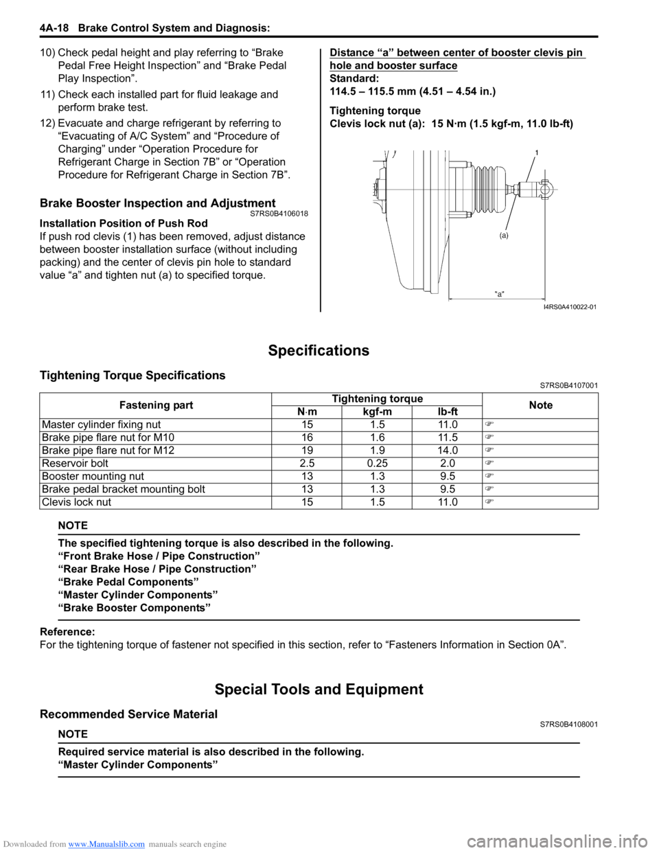
If push rod clevis (1) has b een removed, adjust distance
between booster installation surface (without including
packing) and the center of clevis pin hole to standard
value “a” and tighten nut (a) to specified torque. Distance “a” between center of booster clevis pin
hole and booster surface
Standard:
114.5 – 115.5 mm (4.51 – 4.54 in.)
Tightening torque
Clevis lock nut (a): 15 N·m (1.5 kgf-m, 11.0 lb-ft)
Specifications
Tightening Torque SpecificationsS7RS0B4107001
NOTE
The specified tightening torque is also described in the following.
“Front Brake Hose / Pipe Construction”
“Rear Brake Hose / Pipe Construction”
“Brake Pedal Components”
“Master Cylinder Components”
“Brake Booster Components”
Reference:
For the tightening torque of fastener not specified in this
section, refer to “Fasteners Information in Section 0A”.
Special Tools and Equipment
Recommended Service MaterialS7RS0B4108001
NOTE
Required service material is also described in the following.
“Master Cylinder Components”
I4RS0A410022-01
Fastening part Tightening torque
Note
N ⋅mkgf-mlb-ft
Master cylinder fixing nut 15 1.5 11.0 �)
Brake pipe flare nut for M10 16 1.6 11.5 �)
Brake pipe flare nut for M12 19 1.9 14.0 �)
Reservoir bolt 2.5 0.25 2.0 �)
Booster mounting nut 13 1.3 9.5 �)
Brake pedal bracket mounting bolt 13 1.3 9.5 �)
Clevis lock nut 15 1.5 11.0 �)
Page 750 of 1496
Downloaded from www.Manualslib.com manuals search engine 5A-106 Automatic Transmission/Transaxle:
Automatic Transaxle Unit Dismounting and
Remounting
S7RS0B5106031
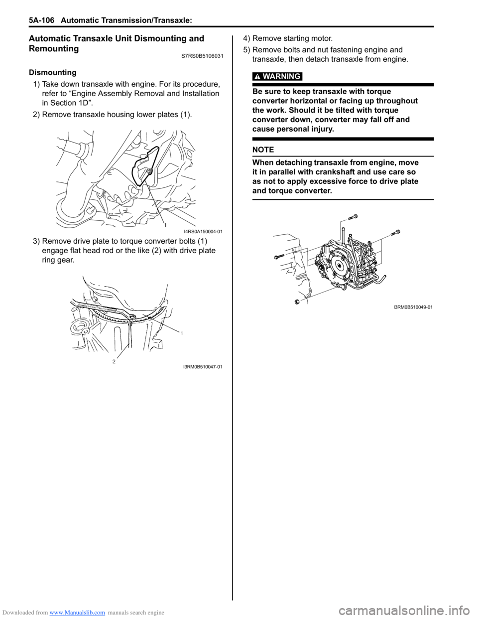
Dismounting1) Take down transaxle with engine. For its procedure, refer to “Engine Assembly Removal and Installation
in Section 1D”.
2) Remove transaxle housing lower plates (1).
3) Remove drive plate to torque converter bolts (1) engage flat head rod or the like (2) with drive plate
ring gear. 4) Remove starting motor.
5) Remove bolts and nut fastening engine and
transaxle, then detach transaxle from engine.WARNING!
Be sure to keep transaxle with torque
converter horizontal or facing up throughout
the work. Should it be tilted with torque
converter down, converter may fall off and
cause personal injury.
NOTE
When detaching transaxle from engine, move
it in parallel with cranks haft and use care so
as not to apply excessive force to drive plate
and torque converter.
1I4RS0A150004-01
I3RM0B510047-01
I3RM0B510049-01
Page 751 of 1496
Downloaded from www.Manualslib.com manuals search engine Automatic Transmission/Transaxle: 5A-107
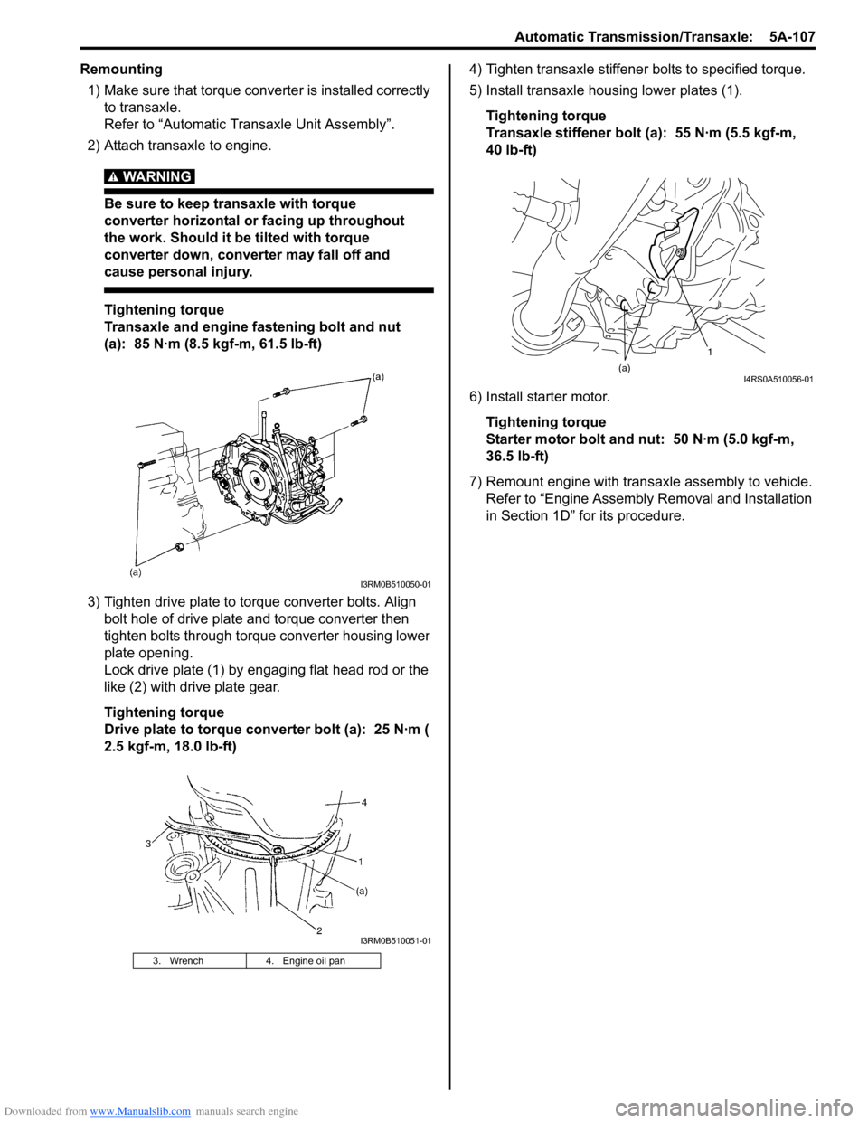
Remounting1) Make sure that torque converter is installed correctly to transaxle.
Refer to “Automatic Transaxle Unit Assembly”.
2) Attach transaxle to engine.
WARNING!
Be sure to keep transaxle with torque
converter horizontal or facing up throughout
the work. Should it be tilted with torque
converter down, converter may fall off and
cause personal injury.
Tightening torque
Transaxle and engine fastening bolt and nut
(a): 85 N·m (8.5 kgf-m, 61.5 lb-ft)
3) Tighten drive plate to torque converter bolts. Align bolt hole of drive plate and torque converter then
tighten bolts through torque converter housing lower
plate opening.
Lock drive plate (1) by engaging flat head rod or the
like (2) with drive plate gear.
Tightening torque
Drive plate to torque converter bolt (a): 25 N·m (
2.5 kgf-m, 18.0 lb-ft) 4) Tighten transaxle stiffener bolts to specified torque.
5) Install transaxle housing lower plates (1).
Tightening torque
Transaxle stiffener bolt (a): 55 N·m (5.5 kgf-m,
40 lb-ft)
6) Install starter motor. Tightening torque
Starter motor bolt and nut: 50 N·m (5.0 kgf-m,
36.5 lb-ft)
7) Remount engine with transaxle assembly to vehicle. Refer to “Engine Assembly Removal and Installation
in Section 1D” for its procedure.
3. Wrench 4. Engine oil pan
I3RM0B510050-01
I3RM0B510051-01
1
(a)
I4RS0A510056-01
Page 754 of 1496
Downloaded from www.Manualslib.com manuals search engine 5A-110 Automatic Transmission/Transaxle:
Automatic Transaxle Unit DisassemblyS7RS0B5106033
CAUTION!
• Thoroughly clean transaxle exterior before overhauling it.
• Keep working table, tools and hands clean while overhauling.
• Use special care to handle aluminum parts so as not to damage them.
• Do not expose removed parts to dust. Keep them always clean.
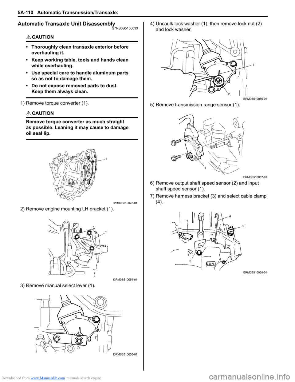
1) Remove torque converter (1).
CAUTION!
Remove torque converte r as much straight
as possible. Leaning it may cause to damage
oil seal lip.
2) Remove engine mounting LH bracket (1).
3) Remove manual select lever (1). 4) Uncaulk lock washer (1),
then remove lock nut (2)
and lock washer.
5) Remove transmission range sensor (1).
6) Remove output shaft speed sensor (2) and input shaft speed sensor (1).
7) Remove harness bracket (3) and select cable clamp (4).
I2RH0B510078-01
I3RM0B510054-01
1
I3RM0B510055-01
1
2
I3RM0B510056-01
I3RM0B510057-01
I3RM0B510058-01
Page 810 of 1496
Downloaded from www.Manualslib.com manuals search engine 5A-166 Automatic Transmission/Transaxle:
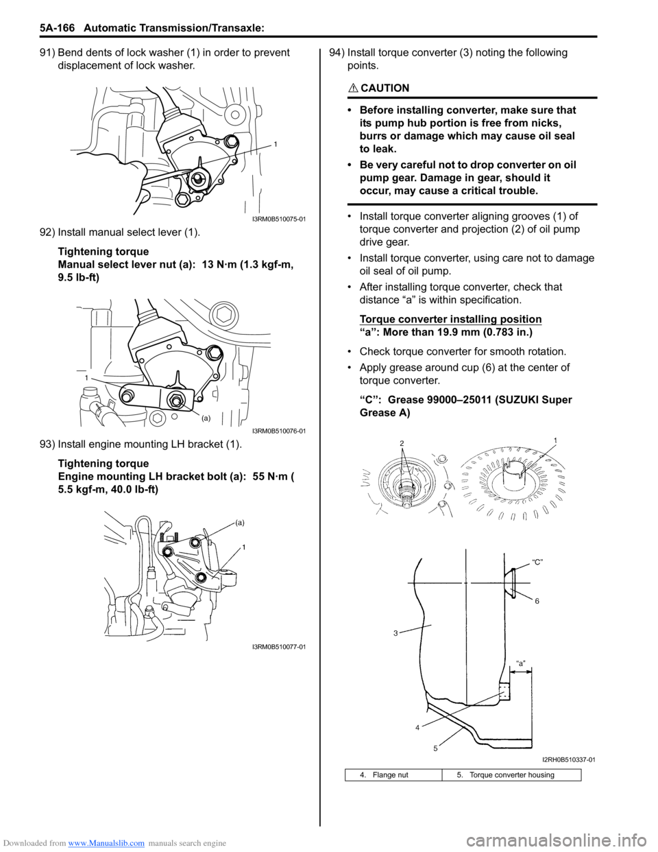
91) Bend dents of lock washer (1) in order to prevent displacement of lock washer.
92) Install manual select lever (1). Tightening torque
Manual select lever nut (a): 13 N·m (1.3 kgf-m,
9.5 lb-ft)
93) Install engine mounting LH bracket (1). Tightening torque
Engine mounting LH bracket bolt (a): 55 N·m (
5.5 kgf-m, 40.0 lb-ft) 94) Install torque converter (3) noting the following
points.
CAUTION!
• Before installing converter, make sure that its pump hub portion is free from nicks,
burrs or damage which may cause oil seal
to leak.
• Be very careful not to drop converter on oil pump gear. Damage in gear, should it
occur, may cause a critical trouble.
• Install torque converter aligning grooves (1) of torque converter and projection (2) of oil pump
drive gear.
• Install torque converter, using care not to damage oil seal of oil pump.
• After installing torque converter, check that distance “a” is within specification.
Torque converter installing position
“a”: More than 19.9 mm (0.783 in.)
• Check torque converter for smooth rotation.
• Apply grease around cup (6) at the center of torque converter.
“C”: Grease 99000–25011 (SUZUKI Super
Grease A)
1
I3RM0B510075-01
1
(a)
I3RM0B510076-01
I3RM0B510077-01
4. Flange nut 5. Torque converter housing
I2RH0B510337-01