2006 SUZUKI SWIFT main bolt
[x] Cancel search: main boltPage 508 of 1496
Downloaded from www.Manualslib.com manuals search engine 4A-10 Brake Control System and Diagnosis:
7) Then attach bleeder plug cap.
8) After completing bleeding operation, apply fluid pressure to pipe line and check for leakage.
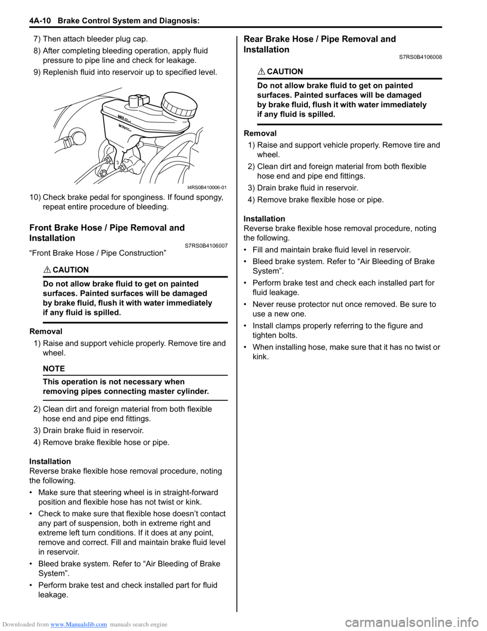
9) Replenish fluid into reserv oir up to specified level.
10) Check brake pedal for sponginess. If found spongy, repeat entire procedure of bleeding.
Front Brake Hose / Pipe Removal and
Installation
S7RS0B4106007
“Front Brake Hose / Pipe Construction”
CAUTION!
Do not allow brake fluid to get on painted
surfaces. Painted surfaces will be damaged
by brake fluid, flush it with water immediately
if any fluid is spilled.
Removal
1) Raise and support vehicle properly. Remove tire and wheel.
NOTE
This operation is not necessary when
removing pipes connecting master cylinder.
2) Clean dirt and foreign mate rial from both flexible
hose end and pipe end fittings.
3) Drain brake fluid in reservoir.
4) Remove brake flexible hose or pipe.
Installation
Reverse brake flexible hose removal procedure, noting
the following.
• Make sure that steering wh eel is in straight-forward
position and flexible hose has not twist or kink.
• Check to make sure that flexible hose doesn’t contact any part of suspension, both in extreme right and
extreme left turn conditions. If it does at any point,
remove and correct. Fill and maintain brake fluid level
in reservoir.
• Bleed brake system. Refer to “Air Bleeding of Brake System”.
• Perform brake test and check installed part for fluid leakage.
Rear Brake Hose / Pipe Removal and
Installation
S7RS0B4106008
CAUTION!
Do not allow brake fluid to get on painted
surfaces. Painted surfaces will be damaged
by brake fluid, flush it with water immediately
if any fluid is spilled.
Removal
1) Raise and support vehicle properly. Remove tire and wheel.
2) Clean dirt and foreign material from both flexible hose end and pipe end fittings.
3) Drain brake fluid in reservoir.
4) Remove brake flexible hose or pipe.
Installation
Reverse brake flexible hose removal procedure, noting
the following.
• Fill and maintain brake fluid level in reservoir.
• Bleed brake system. Refer to “Air Bleeding of Brake System”.
• Perform brake test and check each installed part for fluid leakage.
• Never reuse protector nut once removed. Be sure to use a new one.
• Install clamps properly referring to the figure and tighten bolts.
• When installing hose, make sure that it has no twist or
kink.
I4RS0B410006-01
Page 518 of 1496
Downloaded from www.Manualslib.com manuals search engine 4B-2 Front Brakes:
Front Disc Brake Pad On-Vehicle InspectionS7RS0B4206002
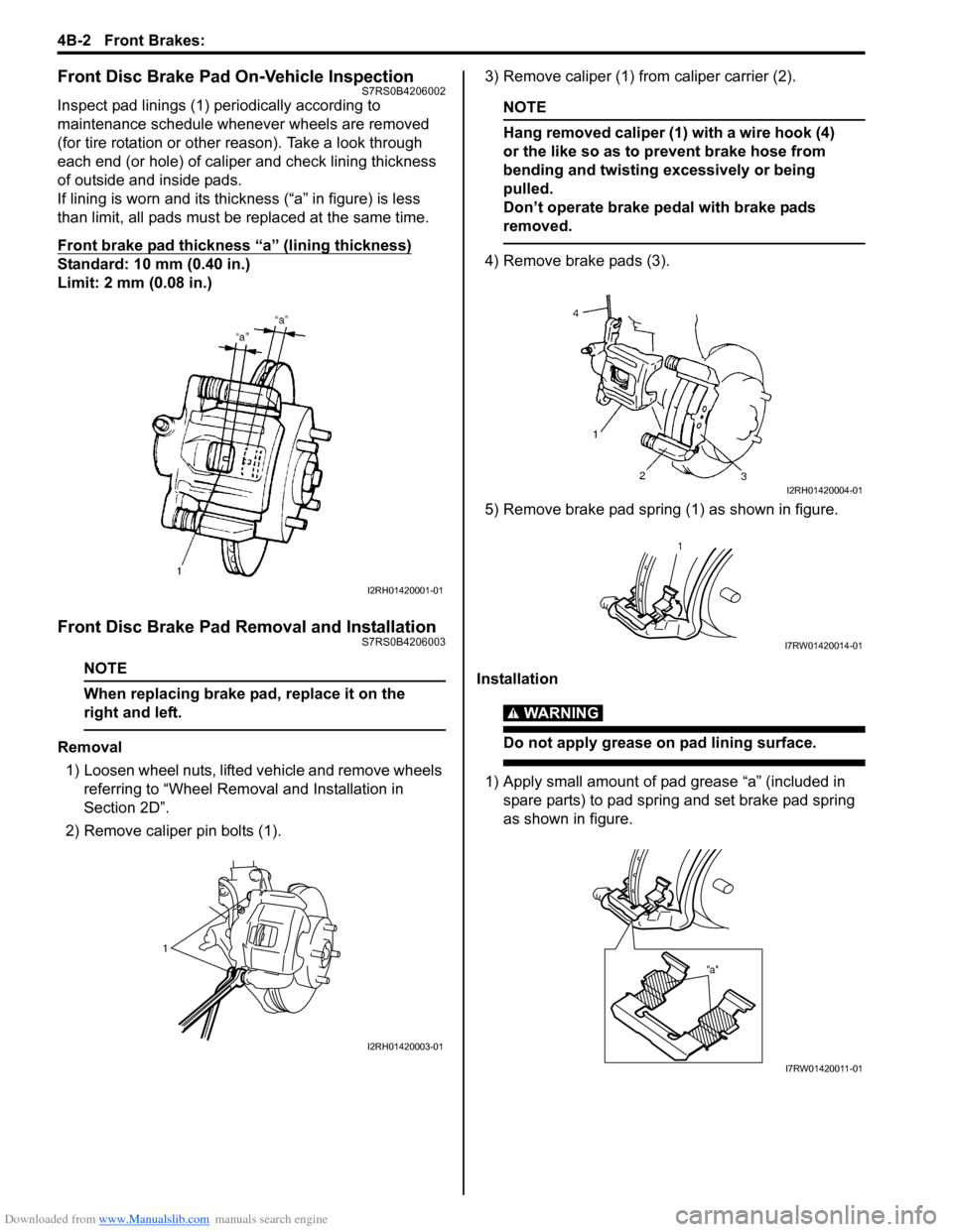
Inspect pad linings (1) periodically according to
maintenance schedule whenever wheels are removed
(for tire rotation or other reason). Take a look through
each end (or hole) of caliper and check lining thickness
of outside and inside pads.
If lining is worn and its thic kness (“a” in figure) is less
than limit, all pads must be replaced at the same time.
Front brake pad thickness “a” (lining thickness)
Standard: 10 mm (0.40 in.)
Limit: 2 mm (0.08 in.)
Front Disc Brake Pad Removal and InstallationS7RS0B4206003
NOTE
When replacing brake pad, replace it on the
right and left.
Removal
1) Loosen wheel nuts, lifted vehicle and remove wheels referring to “Wheel Remova l and Installation in
Section 2D”.
2) Remove caliper pin bolts (1). 3) Remove caliper (1) from caliper carrier (2).
NOTE
Hang removed caliper (1) with a wire hook (4)
or the like so as to prevent brake hose from
bending and twisting excessively or being
pulled.
Don’t operate brake pedal with brake pads
removed.
4) Remove brake pads (3).
5) Remove brake pad spring (1) as shown in figure.
Installation
WARNING!
Do not apply grease on pad lining surface.
1) Apply small amount of pad grease “a” (included in spare parts) to pad spring and set brake pad spring
as shown in figure.
I2RH01420001-01
1
I2RH01420003-01
I2RH01420004-01
1
I7RW01420014-01
"a"
I7RW01420011-01
Page 607 of 1496
Downloaded from www.Manualslib.com manuals search engine Electronic Stability Program: 4F-33
2Check wheel speed sensor circuit
1) Turn ignition switch OFF.
2) Disconnect connector from ESP ® control module and
applicable wheel speed sensor coupler.
3) Check for proper connection of ESP ® control module
and wheel speed sensor coupler.
4) If connections are OK, che ck wheel speed sensor circuit
for the following.
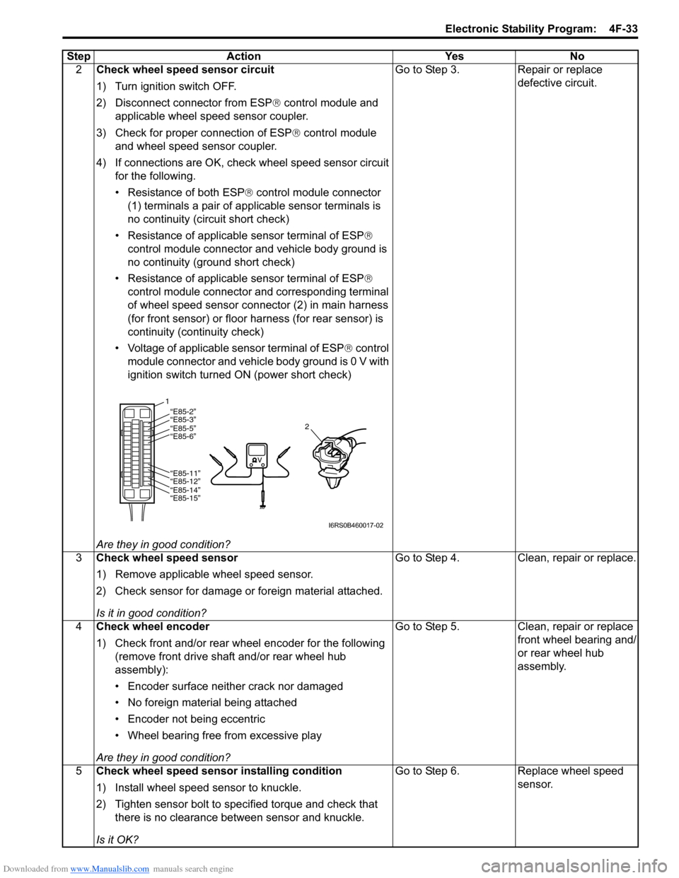
• Resistance of both ESP ® control module connector
(1) terminals a pair of app licable sensor terminals is
no continuity (circuit short check)
• Resistance of applicable sensor terminal of ESP ®
control module connector and vehicle body ground is
no continuity (ground short check)
• Resistance of applicable sensor terminal of ESP ®
control module connector and corresponding terminal
of wheel speed sensor connector (2) in main harness
(for front sensor) or floor harness (for rear sensor) is
continuity (continuity check)
• Voltage of applicable sensor terminal of ESP ® control
module connector and vehicle body ground is 0 V with
ignition switch turned ON (power short check)
Are they in good condition? Go to Step 3. Repair or replace
defective circuit.
3 Check wheel speed sensor
1) Remove applicable wheel speed sensor.
2) Check sensor for damage or foreign material attached.
Is it in good condition? Go to Step 4. Clean, repair or replace.
4 Check wheel encoder
1) Check front and/or rear wheel encoder for the following
(remove front drive shaft and/or rear wheel hub
assembly):
• Encoder surface neither crack nor damaged
• No foreign material being attached
• Encoder not being eccentric
• Wheel bearing free from excessive play
Are they in good condition? Go to Step 5. Clean, repair or replace
front wheel bearing and/
or rear wheel hub
assembly.
5 Check wheel speed sensor installing condition
1) Install wheel speed sensor to knuckle.
2) Tighten sensor bolt to specified torque and check that
there is no clearance between sensor and knuckle.
Is it OK? Go to Step 6. Replace wheel speed
sensor.
Step Action Yes No
1
2“E85-2”“E85-3”“E85-5”
“E85-6”
“E85-11”
“E85-12”
“E85-14”
“E85-15”
I6RS0B460017-02
Page 662 of 1496

Downloaded from www.Manualslib.com manuals search engine 5A-18 Automatic Transmission/Transaxle:
Visual InspectionS7RS0B5104002
Visually check the following parts and systems.
Malfunction Indicator Lamp (MIL) CheckS7RS0B5104003
Refer to the same item in “Malfunction Indicator Lam p (MIL) Check in Section 1A” for checking procedure.
Transmission Warning Light CheckS7RS0B5104004
1) Turn ignition switch ON.
2) Check that transmission warning light lights for about 2 – 4 sec. and then goes OFF.
If anything faulty is found, advance “Transmission Warn ing Light Circuit Check – Light Does Not Come “ON” at
Ignition Switch ON” or “Transmission Warning Light Circu it Check – Light Remains “ON” at Ignition Switch ON”.
Inspection item Referring
• A/T fluid ----- level, leakage, color “Automatic Transaxle Fluid Level Inspection in Section 0B”
• A/T fluid hoses ----- disconnection, looseness, deterioration “A/T Fluid Cooler Hoses Replacement”
• A/T select cable ----- installation “S elect Cable Removal and Installation”
• Engine oil ----- level, leakage “Engine Oil and Filter Change in Section 0B”
• Engine coolant ----- level, leakage “Engine Coolant Change in Section 0B”
• Engine mountings ----- play, looseness, damage “Engine Assembly Removal and Installation in Section 1D”
• Suspension ----- play, looseness “Suspension, Wheels and Tires Symptom Diagnosis in Section 2A”
• Drive shafts ----- damage “Front Drive Shaft Assembly On-Vehicle Inspection in Section 3A”
• Battery ----- indicator condition, corrosion of terminal “Battery Inspection in Section 1J”
• Connectors of electric wire harness ----- disconnection, friction “Electronic Shift Control System Components
Location”
• Fuses ----- burning
• Parts ----- installation, damage
• Bolts ----- looseness
• Other parts that can be checked visually
Also check the following items at engine start, if possible.
• Transmission warning light (if equipped) ----- Operation “Transmission Warning Light Check”
• Malfunction indicator lamp ----- Operation “Malfunction Indicator Lamp (MIL) Check”
• Charge warning lamp ----- Operation “Generator Symptom Diagnosis in Section 1J”
• Engine oil pressure warning lamp ----- Operation “Oil Pressure Warning Ligh t Symptom Diagnosis in
Section 9C”
• Engine coolant temp. meter ----- Operation “Engine Coolant Temperature (ECT) Meter
Symptom Diagnosis in Section 9C”
• Other parts that can be checked visually
I4RS0A510008-01
Page 872 of 1496
Downloaded from www.Manualslib.com manuals search engine 6B-1 Steering Wheel and Column:
Steeri ng
Steering Wheel and Column
Precautions
Service Precautions of Steering Wheel and
Column
S7RS0B6200001
For service precautions, refer to “Precautions on Service
and Diagnosis of Air Bag System in Section 8B”.
Service and Diagnosis
For diagnosis and servicing, refer to “Precautions on
Service and Diagnosis of Air Bag System in Section 8B”.
Disabling Air Bag System
For disabling air bag system, refer to “Disabling Air Bag
System in Section 8B”. Enabling Air Bag System
For enabling air bag system, refer to “Enabling Air Bag
System in Section 8B”.
Handling and Storage
For handling and storage, refer to “Precautions on
Handling and Storage of Air Bag System Components in
Section 8B”.
Disposal
For disposal, refer to “Prec
autions on Disposal of Air
Bag and Seat Belt Pretensioner in Section 8B”.
General Description
Steering Wheel and Column ConstructionS7RS0B6201001
This double tube type steering column has the following three important features in addition to the steering function:
• The column is energy absorbing, desig ned to compress in a front-end collision.
• The ignition switch and lock are mounted conveniently on this column.
• With the column mounted lock, the ignition and steering op erations can be locked to inhibit theft of the vehicle.
To insure the energy absorbing action, it is important th at only the specified screws, bolts and nuts be used as
designated, and that they are tightened to the specified torque. When the column assembly is removed from the
vehicle, special care must be taken in handling it. Use of a steering wheel puller or a sharp blow on the end of the
steering shaft, leaning on the assembly, or dropping the a ssembly could shear the plastic shear pins which maintain
column length and position.
The driver air bag (inflator) module is one of the supplemental restraint (air bag) system components and is mounted
to the center of the steering wheel. During certain frontal crashes, the air bag system supplements the restraint of the
driver’s and passenger’s seat belts by deploying the air b ags. The air bag (inflator) module should be handled with
care to prevent accidental deployment. When servicing, be sure to observe “Precautions on Service and Diagnosis of
Air Bag System in Section 8B”.
Page 878 of 1496
Downloaded from www.Manualslib.com manuals search engine 6B-7 Steering Wheel and Column:
Steering Column Removal and InstallationS7RS0B6206006
CAUTION!
Once the steering column is removed from
the vehicle, the column is extremely
susceptible to damage.
• Dropping the column assembly on its end could collapse the steering shaft or loosen
the plastic shear pins which maintain
column length.
• Leaning on the column assembly could cause it to bend or deform.
Any of the damage could impair the column’s
collapsible design.
Steering column mounting nuts should not
be loosened with steering shaft joint upper
side bolt tightened as this could cause
damage to shaft joint bearing.
NOTE
When servicing steering column or any
column-mounted component, remove
steering wheel. But when removing steering
column simply to gain access to instrument
panel components, leave steering wheel
installed on steering column.
Removal
WARNING!
Never rest a steering column assembly on
the steering wheel with the air bag (inflator)
module face down and column vertical.
Otherwise, personal injury may result.
1) Disconnect negative (–) cable at battery.
2) Disable air bag system. Re fer to “Disabling Air Bag
System in Section 8B”.
3) Remove steering wheel and contact coil cable assembly referring to “S teering Wheel Removal and
Installation” and “Contact Coil Cable Assembly
Removal and Installation”.
4) Detach lighting switch and wiper switch from steering column.
5) Remove immobilizer cont rol module from steering
column, referring to “Immo bilizer Control Module
(ICM) Removal and Installation in Section 10C”.
6) Remove steering column hole cover.
7) Remove steering joint cover.
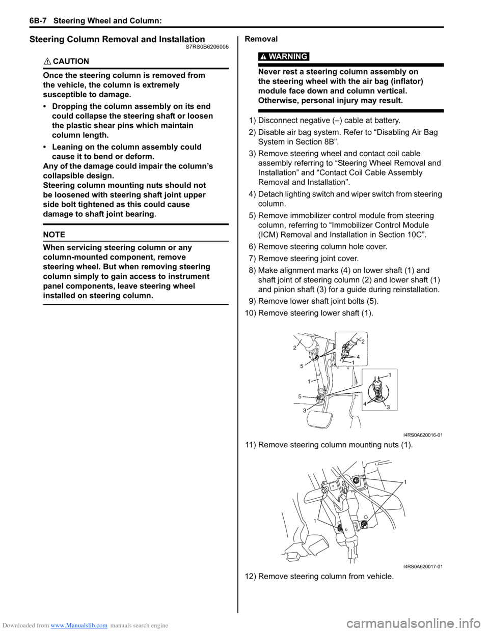
8) Make alignment marks (4) on lower shaft (1) and shaft joint of steering column (2) and lower shaft (1)
and pinion shaft (3) for a guide during reinstallation.
9) Remove lower shaf t joint bolts (5).
10) Remove steering lower shaft (1).
11) Remove steering column mounting nuts (1).
12) Remove steering column from vehicle.
I4RS0A620016-01
1
1
I4RS0A620017-01
Page 975 of 1496
Downloaded from www.Manualslib.com manuals search engine Air Conditioning System: Manual Type 7B-27
A/C Switch InspectionS7RS0B7216014
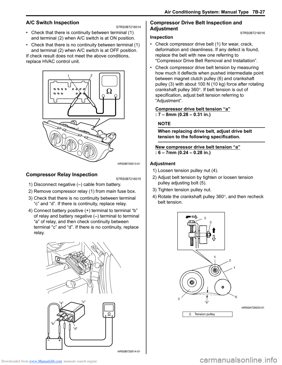
• Check that there is continuity between terminal (1) and terminal (2) when A/C s witch is at ON position.
• Check that there is no continuity between terminal (1) and terminal (2) when A/C s witch is at OFF position.
If check result does not meet the above conditions,
replace HVAC control unit.
Compressor Relay InspectionS7RS0B7216015
1) Disconnect negative (–) cable from battery.
2) Remove compressor relay (1) from main fuse box.
3) Check that there is no continuity between terminal “c” and “d”. If there is continuity, replace relay.
4) Connect battery positive (+ ) terminal to terminal “b”
of relay and battery negative (–) terminal to terminal
“a” of relay, and then check continuity between
terminal “c” and “d”. If there is no continuity, replace
relay.
Compressor Drive Belt Inspection and
Adjustment
S7RS0B7216016
Inspection
• Check compressor drive belt (1) for wear, crack, deformation and cleanliness. If any defect is found,
replace the belt with new one referring to
“Compressor Drive Belt Re moval and Installation”.
• Check compressor drive belt tension by measuring how much it deflects when pushed intermediate point
between magnet clutch pulley (6) and crankshaft
pulley (3) with about 100 N (10 kg) force after rotating
crankshaft pulley 360 °. If belt tension is out of
specification, adjust belt tension referring to
“Adjustment”.
Compressor drive belt tension
“a”
: 7 – 8mm (0.28 – 0.31 in.)
NOTE
When replacing drive belt, adjust drive belt
tension to the following specification.
New compressor dr ive belt tension “a”
: 6 – 7mm (0.24 – 0.28 in.)
Adjustment 1) Loosen tension pulley nut (4).
2) Adjust belt tension by ti ghten or loosen tension
pulley adjusting bolt (5).
3) Tighten tension pulley nut.
4) Rotate the crankshaft pulley 360 °, and then recheck
belt tension.
1 2
I4RS0B720013-01
"d"
"b" "a"
"c"
1
I4RS0B720014-01
2. Tension pulley
I4RS0A720033-01