Page 397 of 1496

Downloaded from www.Manualslib.com manuals search engine Ignition System: 1H-5
6Ignition coil assembly power supply and ground circuit
check
1) Check ignition coil assembly power supply and ground
circuits for open and short.
Are circuits in good condition? Go to Step 7.
Repair or replace.
7 Ignition coil assembly check
1) Check ignition coil for resistance referring to “Ignition
Coil Assembly (Including ignitor) Inspection”.
Is check result satisfactory? Go to Step 8.
Replace ignition coil
assembly.
8 CKP sensor check
1) Check CKP sensor referring to “CKP Sensor Inspection
in Section 1C”.
Is check result satisfactory? Go to Step 9.
Tighten CKP sensor
bolt, replace CKP
sensor or CKP sensor
plate.
9 CMP sensor check
1) Check CMP sensor referring to “Camshaft Position
(CMP) Sensor Inspection in Section 1C”.
Is check result satisfactory? Go to Step 10. Tighten CMP sensor
bolt, replace CMP
sensor or intake
camshaft.
10 Ignition trigger signal circuit check
1) Check ignition trigger signal wire for open, short and
poor connection.
Is circuit in good condition? Go to Step 11. Repair or replace.
11 A known-good ignition coil assembly substitution
1) Substitute a known-good ignition coil assembly and then
repeat Step 2.
Is check result of Step 2 satisfactory? Go to Step 12. Substitute a known-
good ECM and then
repeat Step 2.
12 Knock sensor check
1) Confirm that knock sensor circuit is in good condition
referring to “DTC P0327 / P0328: Knock Sensor 1 Circuit
Low / High in Section 1A”.
2) Check oscilloscope waveform of knock sensor signal
referring to “Reference waveform No.25” and
“Reference waveform No.26” under “Inspection of ECM
and Its Circuits in Section 1A”.
Is check result satisfactory? Go to Step 13. Substitute a known-
good knock sensor and
recheck.
13 Ignition timing check
1) Check initial ignition timing and ignition timing advance
referring to “Ignition Timing Inspection”.
Is check result satisfactory? System is in good
condition.
Check CMP sensor,
CMP sensor rotor tooth
of camshaft, CKP
sensor, CKP sensor
plate and/or input
signals related to this
system.
Step
Action YesNo
Page 401 of 1496

Downloaded from www.Manualslib.com manuals search engine Ignition System: 1H-9
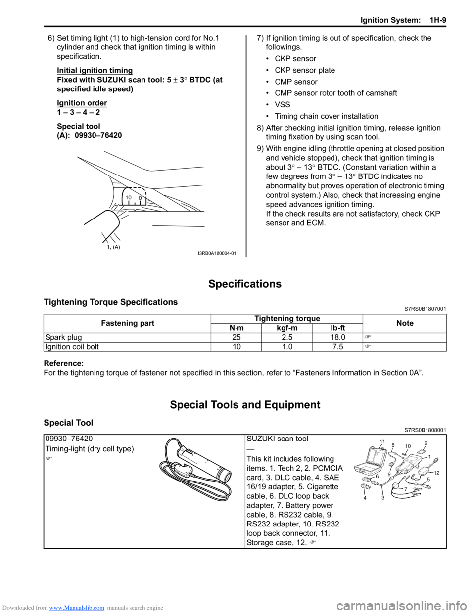
6) Set timing light (1) to high-tension cord for No.1 cylinder and check that ignition timing is within
specification.
Initial ignition timing
Fixed with SUZUKI scan tool: 5 ± 3° BTDC (at
specified idle speed)
Ignition order
1 – 3 – 4 – 2
Special tool
(A): 09930–76420 7) If ignition timing is out
of specification, check the
followings.
• CKP sensor
• CKP sensor plate
• CMP sensor
• CMP sensor rotor tooth of camshaft
• VSS
• Timing chain cover installation
8) After checking initial igniti on timing, release ignition
timing fixation by using scan tool.
9) With engine idling (throttl e opening at closed position
and vehicle stopped), check that ignition timing is
about 3 ° – 13° BTDC. (Constant variation within a
few degrees from 3 ° – 13° BTDC indicates no
abnormality but proves operation of electronic timing
control system.) Also, check that increasing engine
speed advances ignition timing.
If the check results are not satisfactory, check CKP
sensor and ECM.
Specifications
Tightening Torque SpecificationsS7RS0B1807001
Reference:
For the tightening torque of fastener not specified in this section, refer to “Fasteners Information in Section 0A”.
Special Tools and Equipment
Special ToolS7RS0B1808001
1, (A)10
0I3RB0A180004-01
Fastening part Tightening torque
Note
N ⋅mkgf-mlb-ft
Spark plug 25 2.5 18.0 �)
Ignition coil bolt 10 1.0 7.5 �)
09930–76420SUZUKI scan tool
Timing-light (dry cell type) —
�) This kit includes following
items. 1. Tech 2, 2. PCMCIA
card, 3. DLC cable, 4. SAE
16/19 adapter, 5. Cigarette
cable, 6. DLC loop back
adapter, 7. Battery power
cable, 8. RS232 cable, 9.
RS232 adapter, 10. RS232
loop back connector, 11.
Storage case, 12. �)
Page 739 of 1496

Downloaded from www.Manualslib.com manuals search engine Automatic Transmission/Transaxle: 5A-95
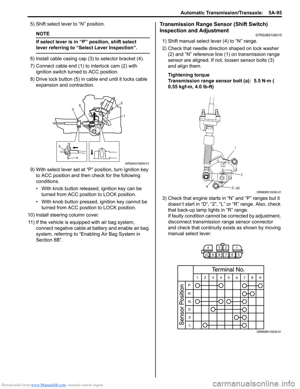
5) Shift select lever to “N” position.
NOTE
If select lever is in “P” position, shift select
lever referring to “Select Lever Inspection”.
6) Install cable casing cap (3) to selector bracket (4).
7) Connect cable end (1) to interlock cam (2) with ignition switch turned to ACC position.
8) Drive lock button (5) in cable end until it locks cable expansion and contraction.
9) With select lever set at “P ” position, turn ignition key
to ACC position and then check for the following
conditions.
• With knob button released, ignition key can be turned from ACC position to LOCK position.
• With knob button pressed, ignition key cannot be
turned from ACC position to LOCK position.
10) Install steering column cover. 11) If the vehicle is equipped with air bag system, connect negative cable at battery and enable air bag
system, referring to “Enabling Air Bag System in
Section 8B”.
Transmission Range Sensor (Shift Switch)
Inspection and Adjustment
S7RS0B5106015
1) Shift manual select lever (4) to “N” range.
2) Check that needle direction shaped on lock washer (2) and “N” reference line (1) on transmission range
sensor are aligned. If not, loosen sensor bolts (3)
and align them.
Tightening torque
Transmission range sensor bolt (a): 5.5 N·m (
0.55 kgf-m, 4.0 lb-ft)
3) Check that engine starts in “N” and “P” ranges but it doesn’t start in “D”, “2”, “L” or “R” range. Also, check
that back-up lamp lights in “R” range.
If faulty condition cannot be corrected by adjustment,
disconnect transmission range sensor connector
and check that continuity ex ists as shown by moving
manual select lever.
3
4 1
2
3 5
I4RS0A510055-01
I3RM0B510038-01
4
3
2
1
98 76 5
12 345
6789
P
R N
D 2
L
I3RM0B510039-01
Page 877 of 1496

Downloaded from www.Manualslib.com manuals search engine Steering Wheel and Column: 6B-6
Centering Contact Coil Cable AssemblyS7RS0B6206004
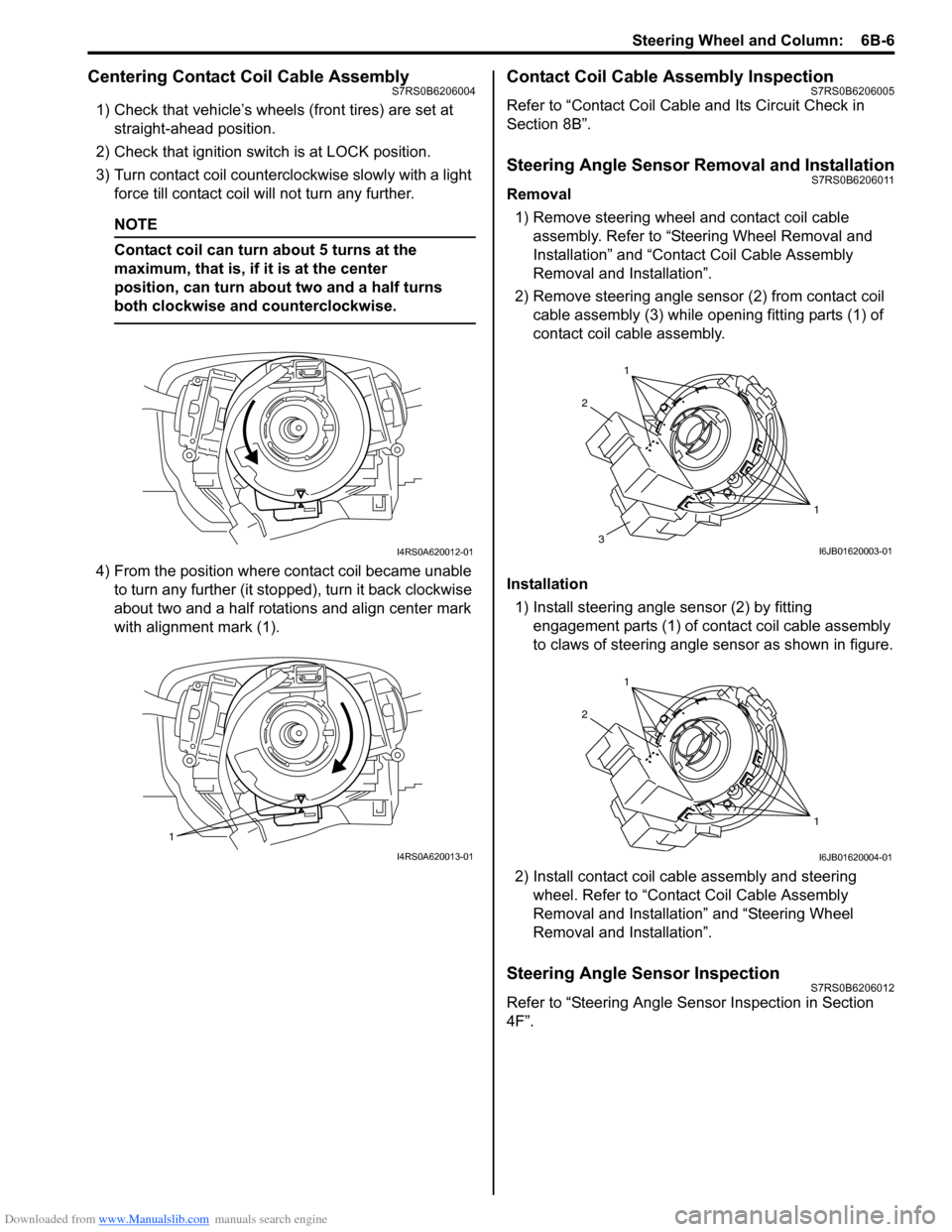
1) Check that vehicle’s wheels (front tires) are set at straight-ahead position.
2) Check that ignition swit ch is at LOCK position.
3) Turn contact coil counterclockwise slowly with a light force till contact coil will not turn any further.
NOTE
Contact coil can turn about 5 turns at the
maximum, that is, if it is at the center
position, can turn about two and a half turns
both clockwise and counterclockwise.
4) From the position where contact coil became unable to turn any further (it stopped), turn it back clockwise
about two and a half rotations and align center mark
with alignment mark (1).
Contact Coil Cable Assembly InspectionS7RS0B6206005
Refer to “Contact Coil Cable and Its Circuit Check in
Section 8B”.
Steering Angle Sensor Removal and InstallationS7RS0B6206011
Removal
1) Remove steering wheel and contact coil cable assembly. Refer to “Ste ering Wheel Removal and
Installation” and “Contact Coil Cable Assembly
Removal and Installation”.
2) Remove steering angle sensor (2) from contact coil cable assembly (3) while op ening fitting parts (1) of
contact coil cable assembly.
Installation 1) Install steering angle sensor (2) by fitting engagement parts (1) of contact coil cable assembly
to claws of steering angle sensor as shown in figure.
2) Install contact coil cable assembly and steering wheel. Refer to “Contact Coil Cable Assembly
Removal and Installation” and “Steering Wheel
Removal and Installation”.
Steering Angle Sensor InspectionS7RS0B6206012
Refer to “Steering Angle Sens or Inspection in Section
4F”.
I4RS0A620012-01
1
I4RS0A620013-01
1
1
2
3I6JB01620003-01
1
1
2
I6JB01620004-01