2006 SUZUKI SWIFT axle shaft
[x] Cancel search: axle shaftPage 491 of 1496

Downloaded from www.Manualslib.com manuals search engine Drive Shaft / Axle: 3A-13
18) Place differential side boot (or center shaft side) new
big band (3) and new small band (4) onto boot
putting band outer end (1) against forward rotation
(2) as shown in figure.
19) Fasten differential side (or center shaft side) boot band.
• For differential side (or center shaft side) boot big band
Fasten band (1) by drawing hooks (2) with special
tool and engage hooks (3) in slot and window (4).
Special tool
(A): 09943–57021
• For differential side (or center shaft side) boot small band
Fasten band (5) using special tool as shown in
figure.
Distance “a”
: 2.6 ± 1.4 mm (0.102 ± 0.055 in.)
Special tool
(B): 09943–57010
I5JB0A311006-01
(A)
1 4
2 3
(B)
5 “a”
I5RS0B310013-01
Page 492 of 1496

Downloaded from www.Manualslib.com manuals search engine 3A-14 Drive Shaft / Axle:
Center Shaft and Center Bearing Support
Disassembly and Reassembly
S7RS0B3106005
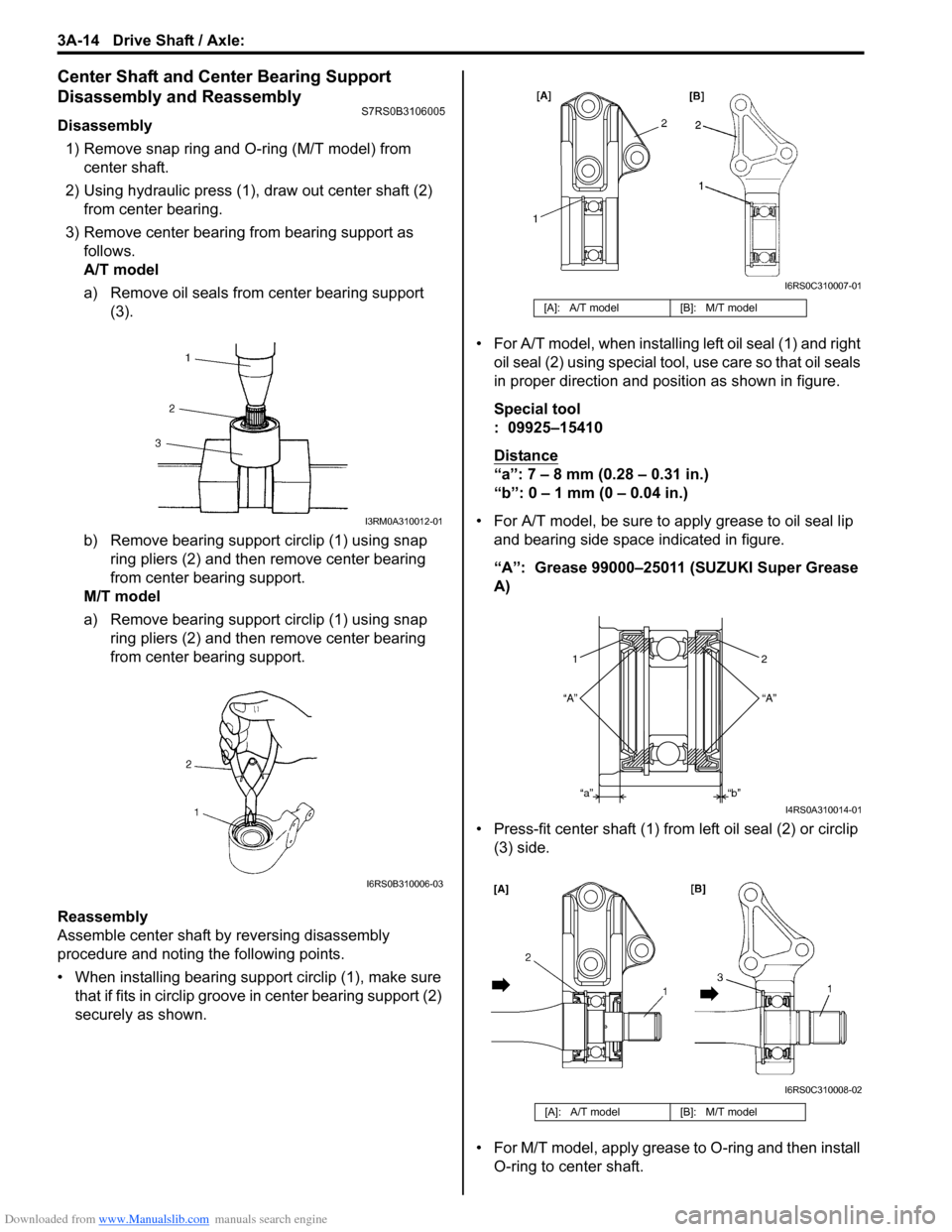
Disassembly1) Remove snap ring and O-ring (M/T model) from center shaft.
2) Using hydraulic press (1), draw out center shaft (2) from center bearing.
3) Remove center bearing from bearing support as follows.
A/T model
a) Remove oil seals from center bearing support (3).
b) Remove bearing support circlip (1) using snap ring pliers (2) and then remove center bearing
from center bearing support.
M/T model
a) Remove bearing support circlip (1) using snap ring pliers (2) and then remove center bearing
from center bearing support.
Reassembly
Assemble center shaft by reversing disassembly
procedure and noting the following points.
• When installing bearing support circlip (1), make sure
that if fits in circlip groove in center bearing support (2)
securely as shown. • For A/T model, when installing
left oil seal (1) and right
oil seal (2) using special tool, use care so that oil seals
in proper direction and position as shown in figure.
Special tool
: 09925–15410
Distance
“a”: 7 – 8 mm (0.28 – 0.31 in.)
“b”: 0 – 1 mm (0 – 0.04 in.)
• For A/T model, be sure to apply grease to oil seal lip and bearing side space indicated in figure.
“A”: Grease 99000–25011 (SUZUKI Super Grease
A)
• Press-fit center shaft (1) from left oil seal (2) or circlip
(3) side.
• For M/T model, apply grease to O-ring and then install O-ring to center shaft.
I3RM0A310012-01
I6RS0B310006-03
[A]: A/T model [B]: M/T model
[A]: A/T model [B]: M/T model
I6RS0C310007-01
12
“A” “A”
“a” “b”
I4RS0A310014-01
I6RS0C310008-02
Page 493 of 1496

Downloaded from www.Manualslib.com manuals search engine Drive Shaft / Axle: 3A-15
Specifications
Tightening Torque SpecificationsS7RS0B3107001
NOTE
The specified tightening torque is also described in the following.
“Front Drive Shaft Assembly Components Location”
Reference:
For the tightening torque of fastener not specified in this section, refer to “Fasteners Information in Section 0A”.
Special Tools and Equipment
Recommended Service MaterialS7RS0B3108001
NOTE
Required service material is also described in the following.
“Front Drive Shaft Components”
Special ToolS7RS0B3108002
Fastening part Tightening torque
Note
N ⋅mkgf-mlb-ft
Brake hose mounting bolt 25 2.5 18.0 �)
MaterialSUZUKI recommended product or Specification Note
Grease SUZUKI Super Grease A P/No.: 99000–25011�)
09913–84510 09925–15410
Bearing installer Oil seal installer
�)�)
09925–98221 09943–57010
Bearing installer Band compressor
�)�) / �) / �)
09943–57021
Pliers, Low-Profile Clamp
�) / �)
Page 494 of 1496

Downloaded from www.Manualslib.com manuals search engine 3A-16 Drive Shaft / Axle:
Page 642 of 1496

Downloaded from www.Manualslib.com manuals search engine 5-ii Table of Contents
DTC P1878: Torque Converter Clutch Shudder .......................................................... 5A-75
DTC P2762: Torque Converter Clutch (TCC) Pressure Control Sole noid Control Circuit
Range /Performance ....................................... 5A-76
DTC P2763: Torque Converter Clutch Pressure Control Sole noid Control Circuit
High ................................................................. 5A-78
DTC P2764: Torque Converter Clutch Circuit Pressure Control Sole noid Control Circuit
Low ................................................................. 5A-80
Inspection of TCM and Its Circuits .................... 5A-82
TCM Power and Ground Circuit Check ............. 5A-86
Brake Interlock System Inspection .................... 5A-87
Repair Instructions ........... .................................5A-88
Learning Control Initializat ion ............................ 5A-88
A/T Fluid Level Check ....................................... 5A-89
A/T Fluid Change .............................................. 5A-90
Select Lever Components ... .............................. 5A-90
Select Lever Assembly Removal and Installation ....................................................... 5A-90
Select Lever Knob Installa tion........................... 5A-90
Select Lever Inspection .... ................................. 5A-91
“3” Position Switch Inspec tion ........................... 5A-91
Shift Lock Solenoid Inspec tion .......................... 5A-91
Shift Lock Solenoid Replacement ..................... 5A-91
Select Cable Components ................................ 5A-92
Select Cable Removal and Installation ............. 5A-92
Select Cable Adjustment ................................... 5A-93
Key Interlock Cable Removal and Installation... 5A-93
Transmission Range Sensor (Shift Switch) Inspection and Adjustment .............................. 5A-95
Output Shaft Speed Sensor Removal and Installation ....................................................... 5A-96
Output Shaft Speed Sensor Inspection ............. 5A-96
Input Shaft Speed Sensor Removal and Installation ....................................................... 5A-96
Input Shaft Speed Sensor Inspection................ 5A-97
Transmission Fluid Temperature Sensor Removal and Installation ................................. 5A-97
Transmission Fluid Temperature Sensor Inspection ........................................................ 5A-98
Solenoid Valves (Shift Solenoid Valves and Timing Solenoid Valve) Removal and
Installation ....................................................... 5A-98
Solenoid Valves (Shift Solenoid Valves, and Timing Solenoid Valve) Inspection .................. 5A-99
Pressure Control Soleno id Valves (Pressure
Control Solenoid and TCC Pressure Control
Solenoid) Removal and Inst allation .............. 5A-101
Pressure Control Solenoid Valve Inspection ... 5A-101
Transmission Control Module (TCM) Removal and Installation ............................... 5A-102
A/T Relay Inspection ....................................... 5A-103
Differential Side Oil Seal Replacement ........... 5A-103
A/T Fluid Cooler Hoses Replacement ............. 5A-104
Automatic Transaxle Unit Components........... 5A-105
Automatic Transaxle Unit Dismounting and Remounting ................................................... 5A-106
Automatic Transaxle Asse mbly Components . 5A-108 Automatic Transaxle Unit
Disassembly........... 5A-110
Oil Pump Assembly Components ................... 5A-121
Oil Pump Assembly Disassembly and Reassembly .................................................. 5A-122
Oil Pump Assembly Inspection ....................... 5A-122
Direct Clutch Assembly Components.............. 5A-124
Direct Clutch Assembly Preliminary Check ..... 5A-124
Direct Clutch Assembly Disassembly and Reassembly .................................................. 5A-125
Direct Clutch Assembly Inspection.................. 5A-127
Forward and Reverse Clutch Assembly Components .................................................. 5A-128
Forward and Reverse Clutch Assembly Preliminary Check ......................................... 5A-129
Forward and Reverse Clutch Assembly Disassembly and Reassembly ...................... 5A-129
Forward and Reverse Clutch Assembly Inspection ...................................................... 5A-133
2nd Brake Piston Assembly Components ....... 5A-134
2nd Brake Piston Assembly Disassembly and Reassembly .................................................. 5A-134
Transaxle Rear Cover (O/D and 2nd Coast Brake Piston) Assembly Components........... 5A-135
Transaxle Rear Cover (O/D and 2nd Coast Brake Piston) Assembly Disassembly and
Reassembly .................................................. 5A-136
Transaxle Rear Cover (O/D and 2nd Coast Brake Piston) Assembly Inspection............... 5A-137
Countershaft Assembly Co mponents.............. 5A-138
Countershaft Assembly Disassembly and Reassembly .................................................. 5A-138
Valve Body Assembly Components ................ 5A-139
Valve Body Assembly Disassembly and Reassembly .................................................. 5A-140
Differential Assembly Components ................. 5A-141
Differential Assembly Disassembly and Reassembly .................................................. 5A-142
Differential Assembly Inspection ..................... 5A-143
Torque Converter Housing Disassembly and Reassembly .................................................. 5A-144
Transaxle Case Disassembly and Reassembly .................................................. 5A-146
Automatic Transaxle Unit Inspection and Adjus
tment .................................................... 5A-147
Automatic Transaxle Unit Assembly ............... 5A-150
Specifications .................. .................................5A-167
Tightening Torque Specifications .................... 5A-167
Special Tools and Equipmen t .........................5A-168
Recommended Service Material ..................... 5A-168
Special Tool .................................................... 5A-168
Manual Transmission/Tr ansaxle ............ 5B-1
General Description .............................................5B-1
Manual Transaxle Construction and Servicing .... 5B-1
Diagnostic Information and Procedures ............5B-3 Manual Transaxle Symptom Diagnosis............... 5B-3
Repair Instructions ............ ..................................5B-3
Manual Transaxle Oil Change............................. 5B-3
Differential Side Oil Seal Replacement ............... 5B-4
Page 643 of 1496

Downloaded from www.Manualslib.com manuals search engine Table of Contents 5-iii
Gear Shift Control Lever and Cable Components...................................................... 5B-5
Gear Shift Control Le ver and Cable Removal
and Installation .................................................. 5B-6
Gear Select Control Cable Adjustment ............... 5B-6
Back Up Light Switch Removal and Installation ......................................................... 5B-7
Back Up Light Switch Inspection ......................... 5B-7
Manual Transaxle Unit Components ................... 5B-8
Manual Transaxle Unit Dismounting and Remounting....................................................... 5B-9
Gear Shift and Sele ct Shaft Assembly
Components.................................................... 5B-11
Gear Shift and Sele ct Shaft Assembly
Removal and Installation................................. 5B-11
Gear Shift and Select Shaft Disassembly and Assembly ........................................................ 5B-12
Manual Transaxle Assembly Components........ 5B-13
Fifth Gear Disassembly and Assembly ............. 5B-14
Manual Transaxle Assembly Disassembly and Reassembly ............................................. 5B-16
Transaxle Right Case Disassembly and Assembly ........................................................ 5B-23
Transaxle Left Case Disassembly and Assembly ........................................................ 5B-24
Input Shaft and Countershaft Components....... 5B-25
Input Shaft Assembly Disassembly and Reassembly .................................................... 5B-26
Countershaft Assembly Disassembly and Reassembly .................................................... 5B-28
Synchronizer Parts Inspec tion .......................... 5B-31
Gear Shift Shaft Components ........................... 5B-31
5th and Reverse Gear Shift Shafts Disassembly and Assembly ............................ 5B-32
Gear Shift Shaft and Fork Inspection ................ 5B-32
Differential Components ................................... 5B-33
Differential Disassembly and Assembly ............ 5B-33
Specifications ..................................................... 5B-35
Tightening Torque Specifications ...................... 5B-35
Special Tools and Equipmen t ........................... 5B-36
Recommended Service Material ....................... 5B-36 Special Tool ...................................................... 5B-36
Clutch ................
.............................. ......... 5C-1
General Description .............................................5C-1
Clutch Construction .............................................5C-1
Diagnostic Information and Procedures ............5C-2 Clutch System Symptom Diagnosis ....................5C-2
Repair Instructions ........... ...................................5C-2
Clutch Pedal Inspection ......................................5C-2
Clutch Fluid Level Inspection ..............................5C-3
Air Bleeding of Clutch System.............................5C-3
Clutch Pedal Position (CPP) Switch Removal and Installation ..................................................5C-4
Clutch Pedal Position (CPP) Switch Inspection and Adjustment ................................5C-5
Clutch Fluid Pipe and Hose Components ...........5C-5
Clutch Fluid Pipe Removal and Installation.........5C-6
Clutch Fluid Pipe Inspection................................5C-6
Clutch Master Cylinder Removal and Installation .........................................................5C-6
Clutch Operating Cylinder Removal and Installation .........................................................5C-7
Clutch Operating Cylinder Inspection..................5C-7
Clutch Pedal and Clutch Pedal Bracket Components ......................................................5C-7
Clutch Cover, Clutch Disc and Flywheel Components ......................................................5C-8
Clutch Cover, Clutch Disc and Flywheel Removal and Installation ...................................5C-8
Clutch Cover, Clutch Disc and Flywheel Inspection ........................................................5C-10
Clutch Release Syst em Removal and
Installation .......................................................5C-11
Clutch Release System Inspection ...................5C-13
Specifications .................... .................................5C-13
Tightening Torque Specifications ......................5C-13
Special Tools and Equipmen t ...........................5C-14
Recommended Service Material .......................5C-14
Special Tool ......................................................5C-14
Page 647 of 1496

Downloaded from www.Manualslib.com manuals search engine Automatic Transmission/Transaxle: 5A-3
General Description
A/T DescriptionS7RS0B5101001
This automatic transaxle is electronic control full automatic transaxle with forward 4-speed and reverse 1-speed.
The torque converter is a 3-element, 1-step and 2-phase type and is equipped with an automatically controlled lock-up
mechanism.
The gear change device consists of a ravigneau type planet ary gear unit, 3 multiple disc type clutches, 3 multiple disc
type brakes and 2 one-way clutches.
The hydraulic pressure control device consists of a valve body assembly, pressure control solenoid valve (linear
solenoid), 2 shift solenoid va lves, TCC pressure control solenoid valve (lin ear solenoid) and a timing solenoid valve.
Optimum line pressure complying with engine torque is produced by the pressure control solenoid valve in
dependence upon control signal from transmission control module (TCM). This makes it possible to control the line
pressure with high accuracy in accordance with the engine power and running conditions to achieve smooth shifting
characteristics and high efficiency.
A clutch-to-clutch control system is prov ided for shifting between 3rd gear and 4th gear. This clutch-to-clutch control
system is made to function optimally , so that hydraulic pressure controls such as shown below are conducted.
• When upshifting from 3rd gear to 4th gear, to adjust the drain hydraulic pressure at releasing the forward clutch, a
timing solenoid valve is used to switch a hydraulic passage with an orifice to another during shifting.
• When downshifting from 4th gear to 3rd gear, to adjust the line pressure applied to the forward clutch at engaging the forward clutch, a timing solenoid valve is used to s witch a hydraulic passage with an orifice to another during
shifting.
• When upshifting from 3rd gear to 4th gear with engine throttle opened, to optimize the line pressure applied to the forward clutch at releasing the forward clutch, the learning control is processed to compensate the switching timing
of the timing solenoid at every shifting.
• When downshifting from 4th gear to 3rd gear with engine throttle opened, to optimize the line pressure applied to
the forward clutch at engaging the forw ard clutch, the learning control is processed to compensate the line pressure
at every shifting.
Employing the ravigneau type planetary gear unit and this clutch-to-clutch control system greatly simplifies the
construction to make possible a lightweight and compact transaxle.
A line pressure learning control is conducted to provide opti mum shifting time at every upshifting with engine throttle
opened. If long upshifting time is detected, the subsequent line pressure applied during upshifting is intensified. On the
contrary, if short upshifting time is detected, the subs equent line pressure applied during upshifting is weakened.
Slip controlled lock-up function
Even at a lower speed than when the TCC gets engaged completely, control over the TCC pressure control solenoid
works to cause the TCC to slip (be engaged slightly), ther eby improving the transmission efficiency. While such slip
control is being executed, the oil pressure applied to the TCC is controlled by the TCC pressure control solenoid so
that the difference between the engine speed and the input shaft speed becomes close to the specified value.
Also, during deceleration, the TCC is made to slip (be enga ged slightly) to raise the engine speed and enlarge the fuel
cut operation range so that better fuel consumption is achieved.
Due to this reason, it is absolutely necessary for the automati c transmission to use ATF suitable for slip control. Use of
any fluid other than the specified ATF may cause j uddering or some other faulty condition to occur.
Page 648 of 1496

Downloaded from www.Manualslib.com manuals search engine 5A-4 Automatic Transmission/Transaxle:
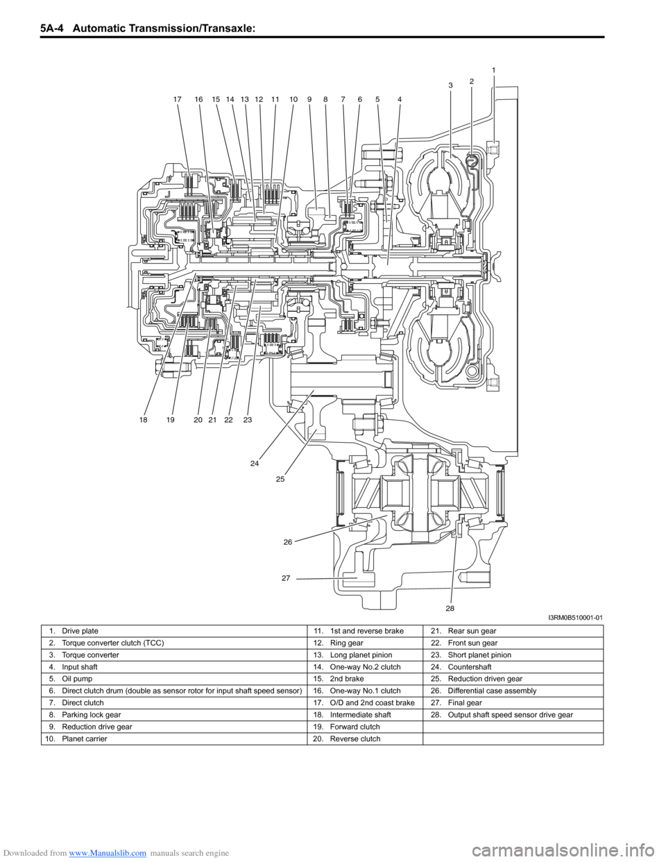
1
2
3
4567891011121314151617
18 19 20 21 22 23
24 25
26
27
28I3RM0B510001-01
1. Drive plate 11. 1st and reverse brake 21. Rear sun gear
2. Torque converter clutch (TCC) 12. Ring gear22. Front sun gear
3. Torque converter 13. Long planet pinion23. Short planet pinion
4. Input shaft 14. One-way No.2 clutch 24. Countershaft
5. Oil pump 15. 2nd brake25. Reduction driven gear
6. Direct clutch drum (double as sensor ro tor for input shaft speed sensor) 16. One-way No.1 clutch 26. Differential case assembly
7. Direct clutch 17. O/D and 2nd coast brake 27. Final gear
8. Parking lock gear 18. Intermediate shaft28.Output shaft speed sensor drive gear
9. Reduction drive gear 19. Forward clutch
10. Planet carrier 20. Reverse clutch