Page 1436 of 1496

Downloaded from www.Manualslib.com manuals search engine 10B-33 Body Electrical Control System:
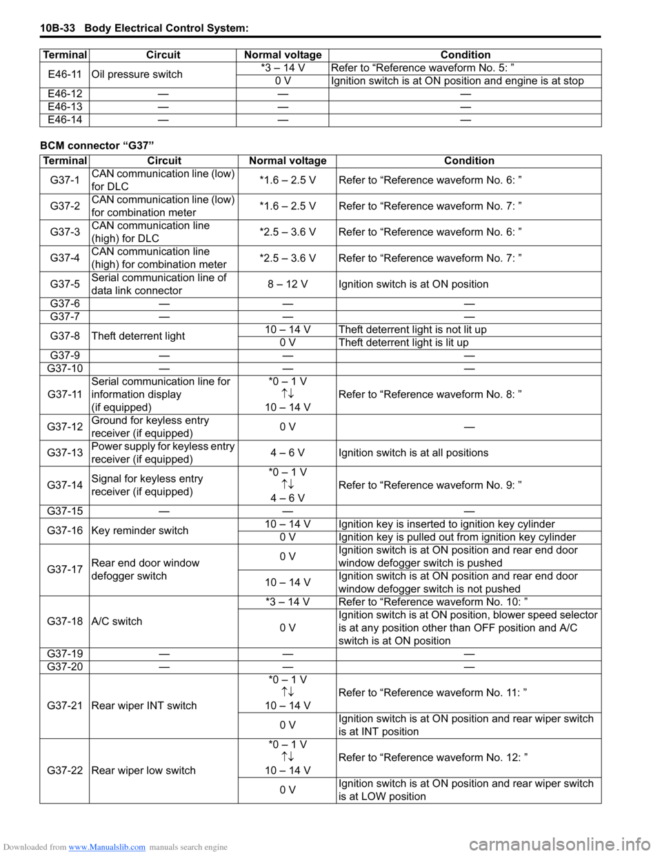
BCM connector “G37”E46-11 Oil pressure switch
*3 – 14 V Refer to “Reference waveform No. 5: ”
0 V Ignition switch is at ON position and engine is at stop
E46-12 — — —
E46-13 — — —
E46-14 — — —
Terminal Circuit Normal voltage Condition
Terminal
CircuitNormal voltage Condition
G37-1 CAN communication line (low)
for DLC *1.6 – 2.5 V Refer to “Reference waveform No. 6: ”
G37-2 CAN communication line (low)
for combination meter *1.6 – 2.5 V Refer to “Reference waveform No. 7: ”
G37-3 CAN communication line
(high) for DLC *2.5 – 3.6 V Refer to “Reference waveform No. 6: ”
G37-4 CAN communication line
(high) for combination meter *2.5 – 3.6 V Refer to “Reference waveform No. 7: ”
G37-5 Serial communication line of
data link connector 8 – 12 V Ignition switch is at ON position
G37-6 — — —
G37-7 — — —
G37-8 Theft deterrent light 10 – 14 V Theft deterrent light is not lit up
0 V Theft deterrent light is lit up
G37-9 — — —
G37-10 — — —
G37-11 Serial communication line for
information display
(if equipped) *0 – 1 V
↑↓
10 – 14 V Refer to “Reference
waveform No. 8: ”
G37-12 Ground for keyless entry
receiver (if equipped) 0 V
—
G37-13 Power supply for keyless entry
receiver (if equipped) 4 – 6 V Ignition switch is at all positions
G37-14 Signal for keyless entry
receiver (if equipped) *0 – 1 V
↑↓
4 – 6 V Refer to “Reference
waveform No. 9: ”
G37-15 — — —
G37-16 Key reminder switch 10 – 14 V Ignition key is inserted to ignition key cylinder
0 V Ignition key is pulled out from ignition key cylinder
G37-17 Rear end door window
defogger switch 0 V
Ignition switch is at ON
position and rear end door
window defogger switch is pushed
10 – 14 V Ignition switch is at ON
position and rear end door
window defogger switch is not pushed
G37-18 A/C switch *3 – 14 V Refer to “Reference waveform No. 10: ”
0 V Ignition switch is at ON pos
ition, blower speed selector
is at any position other than OFF position and A/C
switch is at ON position
G37-19 — — —
G37-20 — — —
G37-21 Rear wiper INT switch *0 – 1 V
↑↓
10 – 14 V Refer to “Reference
waveform No. 11: ”
0 V Ignition switch is at ON pos
ition and rear wiper switch
is at INT position
G37-22 Rear wiper low switch *0 – 1 V
↑↓
10 – 14 V Refer to “Reference
waveform No. 12: ”
0 V Ignition switch is at ON pos
ition and rear wiper switch
is at LOW position
Page 1437 of 1496

Downloaded from www.Manualslib.com manuals search engine Body Electrical Control System: 10B-34
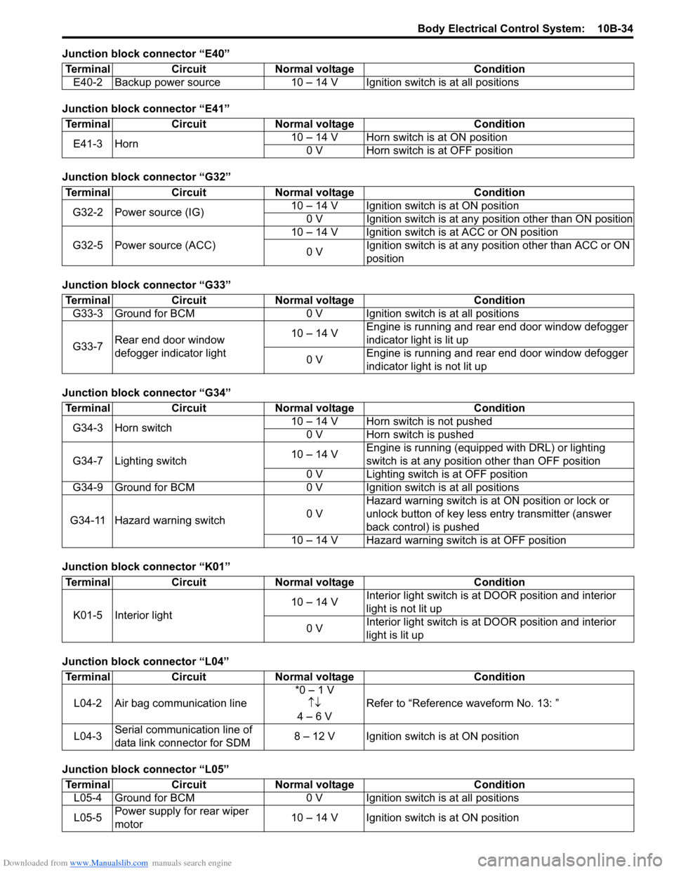
Junction block connector “E40”
Junction block connector “E41”
Junction block connector “G32”
Junction block connector “G33”
Junction block connector “G34”
Junction block connector “K01”
Junction block connector “L04”
Junction block connector “L05”Terminal Circuit Normal voltage Condition
E40-2 Backup power source 10 – 14 V Igni tion switch is at all positions
TerminalCircuitNormal voltage Condition
E41-3 Horn 10 – 14 V Horn switch is at ON position
0 V Horn switch is at OFF position
Terminal CircuitNormal voltage Condition
G32-2 Power source (IG) 10 – 14 V Ignition switch is at ON position
0 V Ignition switch is at any position other than ON position
G32-5 Power source (ACC) 10 – 14 V Ignition switch is at ACC or ON position
0 V Ignition switch is at any position other than ACC or ON
position
Terminal
CircuitNormal voltage Condition
G33-3 Ground for BCM 0 V Ignition switch is at all positions
G33-7 Rear end door window
defogger indicator light 10 – 14 V
Engine is running and rear end door window defogger
indicator light is lit up
0 V Engine is running and rear end door window defogger
indicator light is not lit up
Terminal
CircuitNormal voltage Condition
G34-3 Horn switch 10 – 14 V Horn switch is not pushed
0 V Horn switch is pushed
G34-7 Lighting switch 10 – 14 VEngine is running (equipped with DRL) or lighting
switch is at any position other than OFF position
0 V Lighting switch is at OFF position
G34-9 Ground for BCM 0 V Ignition switch is at all positions
G34-11 Hazard warning switch 0 VHazard warning switch is at
ON position or lock or
unlock button of key less entry transmitter (answer
back control) is pushed
10 – 14 V Hazard warning switch is at OFF position
Terminal CircuitNormal voltage Condition
K01-5 Interior light 10 – 14 V
Interior light switch is at
DOOR position and interior
light is not lit up
0 V Interior light switch is at
DOOR position and interior
light is lit up
Terminal CircuitNormal voltage Condition
L04-2 Air bag communication line *0 – 1 V
↑↓
4 – 6 V Refer to “Reference
waveform No. 13: ”
L04-3 Serial communication line of
data link connector for SDM 8 – 12 V Ignition switch is at ON position
Terminal
CircuitNormal voltage Condition
L05-4 Ground for BCM 0 V Ignition switch is at all positions
L05-5 Power supply for rear wiper
motor 10 – 14 V Ignition switch is at ON position
Page 1438 of 1496

Downloaded from www.Manualslib.com manuals search engine 10B-35 Body Electrical Control System:
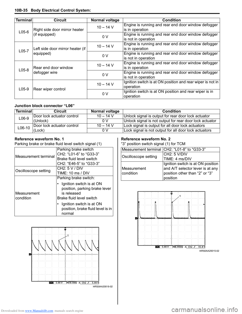
Junction block connector “L06”
Reference waveform No. 1
Parking brake or brake fluid level switch signal (1)Reference waveform No. 2
“3” position switch signal (1) for TCM
L05-6
Right side door mirror heater
(if equipped) 10 – 14 V
Engine is running and rear end door window defogger
is in operation
0 V Engine is running and rear end door window defogger
is not in operation
L05-7 Left side door mirror heater (if
equipped) 10 – 14 V
Engine is running and rear end door window defogger
is in operation
0 V Engine is running and rear end door window defogger
is not in operation
L05-8 Rear end door window
defogger wire 10 – 14 V
Engine is running and rear end door window defogger
is in operation
0 V Engine is running and rear end door window defogger
is not in operation
L05-9 Rear wiper control 10 – 14 V
Ignition switch is at ON posi
tion and rear wiper is not in
operation
0 V Ignition switch is at ON pos
ition and rear wiper is in
operation
Terminal Circuit Normal voltage Condition
Terminal
CircuitNormal voltage Condition
L06-9 Door lock actuator control
(Unlock) 10 – 14 V Unlock signal is outpu
t for rear door lock actuator
0 V Unlock signal is not output for rear door lock actuator
L06-10 Door lock actuator control
(Lock) 10 – 14 V Lock signal is output for all door lock actuators
0 V Lock signal is not output for all door lock actuators
Measurement terminal Parking brake switch
CH2: “L01-6” to “G33-3”
Brake fluid level switch
CH2: “E46-5” to “G33-3”
Oscilloscope setting CH2: 5 V / DIV
TIME: 10 ms / DIV
Measurement
condition Parking brake switch:
• Ignition switch is at ON
position, parking brake lever
is released
Brake fluid level switch
• Ignition switch is at ON position, brake fluid level is in
normal
I4RS0AA20018-02
Measurement terminal CH2: “L01-8” to “G33-3”
Oscilloscope setting CH2: 5 V/DIV
TIME: 4 ms/DIV
Measurement
condition Ignition switch is at ON position
and A/T selector lever is at any
position other than “2” or “3”
position
I4RS0AA20015-02
Page 1441 of 1496
Downloaded from www.Manualslib.com manuals search engine Body Electrical Control System: 10B-38
Reference waveform No. 11
Rear wiper INT signal (1)
Reference waveform No. 12
Rear wiper LOW signal (1)Reference waveform No. 13
SDM communication signal (1)
Measurement terminal CH2: “G37-21” to “G33-3”
Oscilloscope setting CH2: 5 V / DIV
TIME: 10 ms / DIV
Measurement
condition Ignition switch is at ON position
and rear wiper switch is at any
position other than INT position
Measurement terminal CH2: “G37-22” to “G33-3”
Oscilloscope setting CH2: 5 V / DIV
TIME: 4 ms / DIV
Measurement
condition Ignition switch is at ON position
and rear wiper switch is at any
position other than LOW
position
I4RS0AA20024-02
I4RS0AA20025-02
Measurement terminal CH2: “L04-2” to “G33-3”
Oscilloscope setting
CH2: 2 V / DIV
TIME: 400 ms / DIV
Measurement
condition Ignition switch is at ON position
I4RS0AA20026-02