2006 SUZUKI SWIFT HO2S-1
[x] Cancel search: HO2S-1Page 150 of 1496
Downloaded from www.Manualslib.com manuals search engine 1A-100 Engine General Information and Diagnosis:
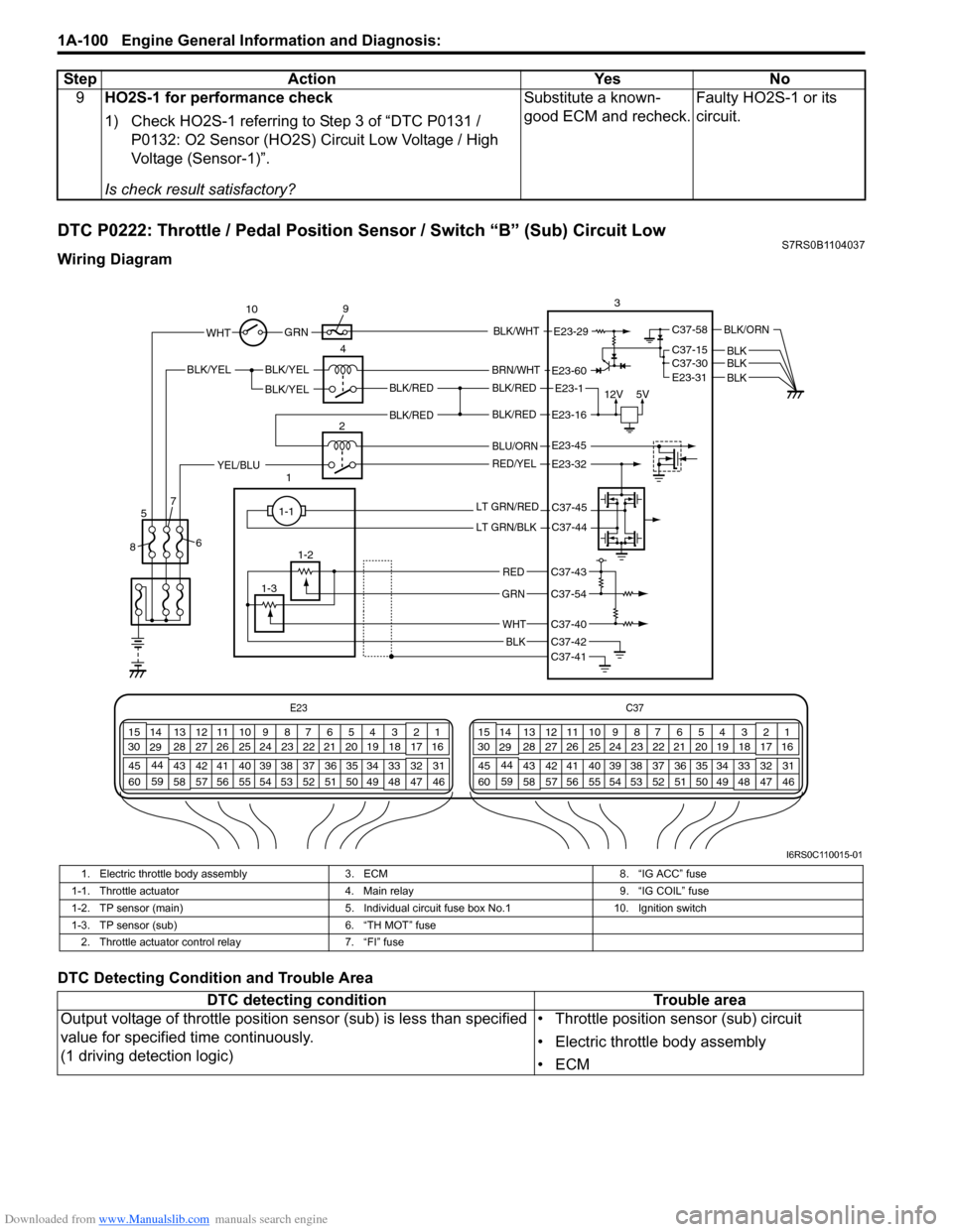
DTC P0222: Throttle / Pedal Position Sensor / Switch “B” (Sub) Circuit LowS7RS0B1104037
Wiring Diagram
DTC Detecting Condition and Trouble Area9
HO2S-1 for performance check
1) Check HO2S-1 referring to Step 3 of “DTC P0131 /
P0132: O2 Sensor (HO2S) Circuit Low Voltage / High
Voltage (Sensor-1)”.
Is check result satisfactory? Substitute a known-
good ECM and recheck.
Faulty HO2S-1 or its
circuit.
Step Action Yes No
E23
C37
34
1819
567
1011
17
20
47 46
495051
2122
52 16
25 9
24
14
29
55
57 54 53
59
60 58 2
262728
15
30
56 4832 31
34353637
40
42 39 38
44
45 43 41 331
1213
238
34
1819
567
1011
17
20
47 46
495051
2122
52 16
25 9
24
14
29
55
57 54 53
59
60 58 2
262728
15
30
56 4832 31
34353637
40
42 39 38
44
45 43 41 331
1213
238
12V
5VBLK/REDBLK/RED
BLK/YEL
12BLK/YEL
BLK/YEL
BRN/WHT
E23-1
E23-60
C37-58
C37-15 C37-30
BLK/ORN
BLKBLKE23-31 BLK
BLK/RED
BLU/ORN
RED/YELYEL/BLU
LT GRN/RED
LT GRN/BLK
RED
GRN
WHT
BLK
E23-16
E23-45
E23-32
C37-45
C37-44
C37-41C37-42
C37-40
C37-54
C37-43
1-1
1-2
1-3 3
4
5
8 67
10
9
E23-29 GRNBLK/WHTWHT
BLK/RED
I6RS0C110015-01
1. Electric throttle body assembly
3. ECM 8. “IG ACC” fuse
1-1. Throttle actuator 4. Main relay 9. “IG COIL” fuse
1-2. TP sensor (main) 5. Individual circuit fuse box No.110. Ignition switch
1-3. TP sensor (sub) 6. “TH MOT” fuse
2. Throttle actuator control relay 7. “FI” fuse
DTC detecting condition Trouble area
Output voltage of throttle position sensor (sub) is less than specified
value for specified time continuously.
(1 driving detection logic) • Throttle position sensor (sub) circuit
• Electric throttle body assembly
•ECM
Page 170 of 1496
Downloaded from www.Manualslib.com manuals search engine 1A-120 Engine General Information and Diagnosis:
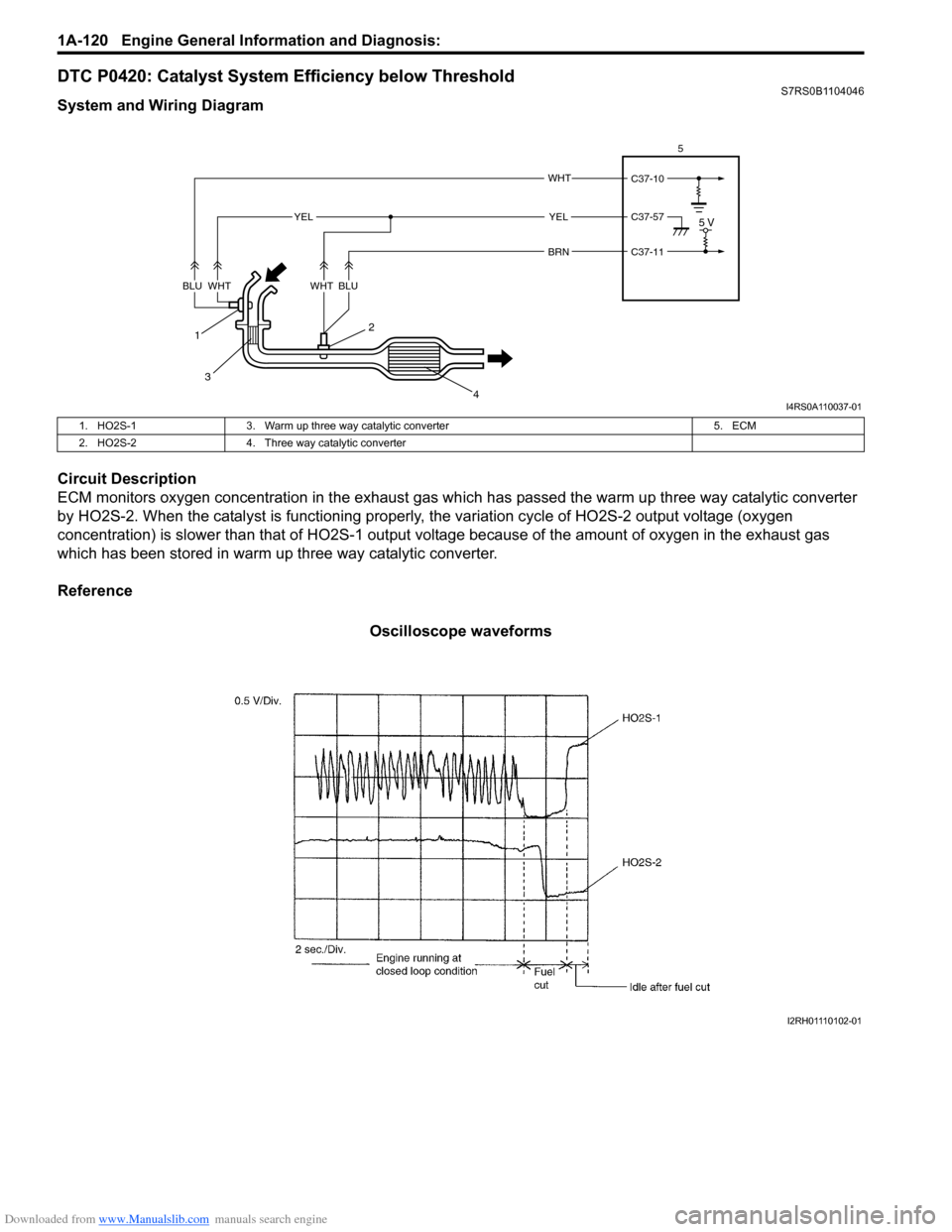
DTC P0420: Catalyst System Efficiency below ThresholdS7RS0B1104046
System and Wiring Diagram
Circuit Description
ECM monitors oxygen concentration in the exhaust gas which has passed the warm up three way catalytic converter
by HO2S-2. When the catalyst is functioning properly, the variation cycle of HO2S-2 output voltage (oxygen
concentration) is slower than that of HO2S-1 output voltage because of the amount of oxygen in the exhaust gas
which has been stored in warm up three way catalytic converter.
Reference
Oscilloscope waveforms
C37-11
C37-10
C37-57
WHT
BRN
1
3 2
4
5 VYELYEL
BLUWHTBLUWHT 5
I4RS0A110037-01
1. HO2S-1
3. Warm up three way catalytic converter 5. ECM
2. HO2S-2 4. Three way catalytic converter
I2RH01110102-01
Page 171 of 1496
Downloaded from www.Manualslib.com manuals search engine Engine General Information and Diagnosis: 1A-121
DTC Detecting Condition and Trouble Area
DTC Confirmation Procedure
WARNING!
• When performing a road test, select a place where there is no traffic or possibility of a traffic accident and be very careful during testing to avoid occurrence of an accident.
• Road test should be carried out by 2 persons, a driver and a tester, on a level road.
NOTE
Check to make sure that following conditions ar e satisfied when using this “DTC Confirmation
Procedure”.
• Intake air temperature at engine start: –10 °C (14 ° F) to 80 °C (176 °F)
• Intake air temperature: –10 °C (14 °F) to 70 °C (158 °F)
• Engine coolant temp.: 70 °C, 158 °F to 150 °C (302 °F)
• Altitude (barometric pressure): 2400 m, 8000 ft or less (500 mmHg, 75 kPa or more)
1) Connect scan tool to DLC with ignition switch turned OFF.
2) Turn ON ignition switch and clear DTC using scan tool.
3) Increase vehicle speed to 37 – 62 mph, 60 – 100 km/h. (engine speed: 2500 – 3000 r/min.)
4) Keep above vehicle speed for 10 min. or more (Thr ottle valve opening is kept constant in this step).
5) Stop vehicle and check if DTC / pending DTC exists using sc an tool. If not, check if catalyst monitoring test has
been completed using scan tool. If not in both of above checks (i.e., no DTC / pending DTC and catalyst
monitoring test not completed), check vehicle cond ition (environmental) and repeat Step 3) through 5).
DTC Troubleshooting
NOTE
• When measuring circuit voltage, resistance and/ or pulse signal at ECM connector, connect the
special tool to ECM and/or the ECM connectors re ferring to “Inspection of ECM and Its Circuits”.
• Upon completion of inspection and repair work, perform “DTC Confirmation Procedure” and confirm that the trouble has been corrected.
DTC detecting condition Trouble area
Response delay of HO2S-2 signal (shifting delay from rich to lean and
from lean to rich with threshold at 0.45 V) compared to switching cycle
(rich-lean) of A/F feed back is less than specified while vehicle is
running at constant speed and except with high engine load after
warmed up.
(*2 driving cycle detection logic, monitoring once per driving cycle) • Exhaust gas leak
• Warm up three way catalytic converter
malfunction
• HO2S-2 malfunction
• HO2S-1 malfunction
Step Action YesNo
1 Was “Engine and Emission Control System Check”
performed? Go to Step 2.
Go to “Engine and
Emission Control
System Check”.
2 Exhaust system visual check
1) Check exhaust system for leaks, damage and loose
connection.
Is it in good condition? Go to Step 3.
Repair or replace
defective part.
Page 227 of 1496
Downloaded from www.Manualslib.com manuals search engine Engine General Information and Diagnosis: 1A-177
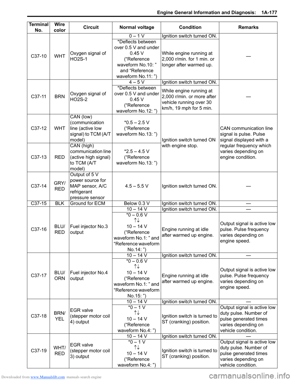
C37-10 WHTOxygen signal of
HO2S-1 0 – 1 V Ignition switch turned ON.
—
*Deflects between
over 0.5 V and under 0.45 V
(“Reference
waveform No.10: ” and “Reference
waveform No.11: ”) While engine running at
2,000 r/min. for 1 min. or
longer after warmed up.
C37-11 BRN Oxygen signal of
HO2S-2 4 – 5 V Ignition switch turned ON.
—
*Deflects between
over 0.5 V and under 0.45 V
(“Reference
waveform No.12: ”) While engine running at
2,000 r/min. or more after
vehicle running over 30
km/h, 19 mph for 5 min.
C37-12 WHT CAN (low)
(communication
line (active low
signal) to TCM (A/T
model) *0.5 – 2.5 V
(“Reference
waveform No.13: ”) Ignition switch turned ON
with engine stop. CAN communication line
signal is pulse. Pulse
signal displayed with a
regular frequency which
varies depending on
engine condition.
C37-13 RED CAN (high)
communication line
(active high signal)
to TCM (A/T
model) *2.5 – 4.5 V
(“Reference
waveform No.13: ”)
C37-14 GRY/
RED Output of 5 V
power source for
MAP sensor, A/C
refrigerant
pressure sensor
4.5 – 5.5 V Ignition switch turned ON. —
C37-15 BLK Ground for ECM Below 0.3 V Ignition switch turned ON. —
C37-16 BLU/
RED Fuel injector No.3
output 10 – 14 V Ignition switch turned ON. —
*0 – 0.6 V ↑↓
10 – 14 V
(“Reference
waveform No.1: ” and
“Reference waveform No.14: ”) Engine running at idle
after warmed up engine.
Output signal is active low
pulse. Pulse frequency
varies depending on
engine speed.
C37-17 BLU/
ORNFuel injector No.4
output 10 – 14 V Ignition switch turned ON. —
*0 – 0.6 V ↑↓
10 – 14 V
(“Reference
waveform No.1: ” and
“Reference waveform No.15: ”) Engine running at idle
after warmed up engine.
Output signal is active low
pulse. Pulse frequency
varies depending on
engine speed.
C37-18 BRN/
YEL EGR valve
(stepper motor coil
4) output 10 – 14 V Ignition switch turned ON. —
*0 – 1 V ↑↓
10 – 14 V
(“Reference
waveform No.4: ”) Ignition switch is turned to
ST (cranking) position. Output signal is active low
duty pulse. Number of
pulse generated times
varies depending on
vehicle condition.
C37-19 WHT/
RED EGR valve
(stepper motor coil
3) output 10 – 14 V Ignition switch turned ON. —
*0 – 1 V ↑↓
1
0 – 14 V
(“Reference
waveform No.4: ”) Ignition switch is turned to
ST (cranking) position. Output signal is active low
duty pulse. Number of
pulse generated times
varies depending on
vehicle condition.
Terminal
No. Wire
color Circuit Normal voltage
ConditionRemarks
Page 229 of 1496
Downloaded from www.Manualslib.com manuals search engine Engine General Information and Diagnosis: 1A-179
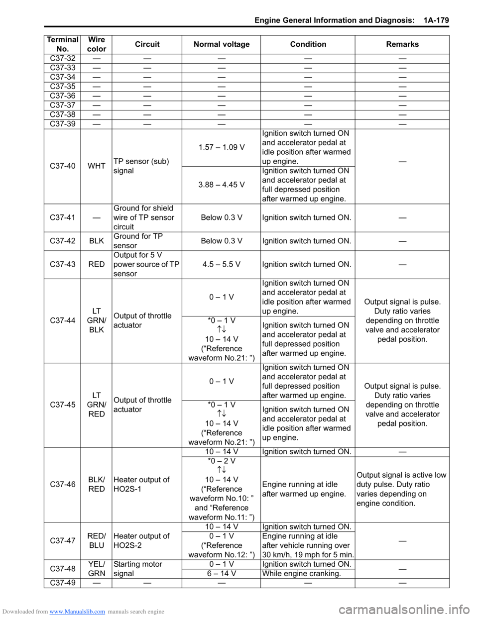
C37-32 ——— — —
C37-33 — —— — —
C37-34 — —— — —
C37-35 — —— — —
C37-36 — —— — —
C37-37 — —— — —
C37-38 — —— — —
C37-39 — —— — —
C37-40 WHT TP sensor (sub)
signal 1.57 – 1.09 V
Ignition switch turned ON
and accelerator pedal at
idle position after warmed
up engine.
—
3.88 – 4.45 V Ignition switch turned ON
and accelerator pedal at
full depressed position
after warmed up engine.
C37-41 — Ground for shield
wire of TP sensor
circuit Below 0.3 V Ignition switch turned ON.
—
C37-42 BLK Ground for TP
sensor Below 0.3 V Ignition switch turned ON.
—
C37-43 RED Output for 5 V
power source of TP
sensor 4.5 – 5.5 V Ignition switch turned ON.
—
C37-44 LT
GRN/ BLK Output of throttle
actuator 0 – 1 V
Ignition switch turned ON
and accelerator pedal at
idle position after warmed
up engine.
Output signal is pulse.
Duty ratio varies
depending on throttle
valve and accelerator pedal position.
*0 – 1 V
↑↓
10 – 14 V
(“Reference
waveform No.21: ”) Ignition switch turned ON
and accelerator pedal at
full depressed position
after warmed up engine.
C37-45 LT
GRN/ RED Output of throttle
actuator 0 – 1 V
Ignition switch turned ON
and accelerator pedal at
full depressed position
after warmed up engine.
Output signal is pulse.
Duty ratio varies
depending on throttle
valve and accelerator pedal position.
*0 – 1 V
↑↓
10 – 14 V
(“Reference
waveform No.21: ”) Ignition switch turned ON
and accelerator pedal at
idle position after warmed
up engine.
C37-46 BLK/
RED Heater output of
HO2S-1 10 – 14 V Ignition switch turned ON.
—
*0 – 2 V ↑↓
10 – 14 V
(“Reference
waveform No.10: ” and “Reference
waveform No.11: ”) Engine running at idle
after warmed up engine.
Output signal is active low
duty pulse. Duty ratio
varies depending on
engine condition.
C37-47 RED/
BLU Heater output of
HO2S-2 10 – 14 V Ignition switch turned ON.
—
0 – 1 V
(“Reference
waveform No.12: ”) Engine running at idle
after vehicle running over
30 km/h, 19 mph for 5 min.
C37-48 YEL/
GRN Starting motor
signal 0 – 1 V Ignition switch turned ON.
—
6 – 14 V While engine cranking.
C37-
49 — —— — —
Terminal
No. Wire
color Circuit Normal voltage
ConditionRemarks
Page 237 of 1496
Downloaded from www.Manualslib.com manuals search engine Engine General Information and Diagnosis: 1A-187
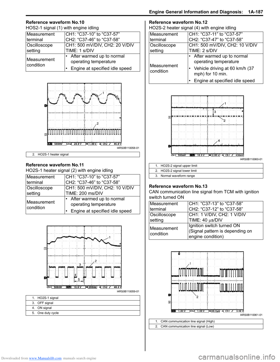
Reference waveform No.10
HOS2-1 signal (1) with engine idling
Reference waveform No.11
HO2S-1 heater signal (2) with engine idlingReference waveform No.12
HO2S-2 heater signal (4) with engine idling
Reference waveform No.13
CAN communication line signal from TCM with ignition
switch turned ON
Measurement
terminal
CH1: “C37-10” to “C37-57”
CH2: “C37-46” to “C37-58”
Oscilloscope
setting CH1: 500 mV/DIV, CH2: 20 V/DIV
TIME: 1 s/DIV
Measurement
condition • After warmed up to normal
operating temperature
• Engine at specified idle speed
2. HO2S-1 heater signal
Measurement
terminal CH1: “C37-10” to “C37-57”
CH2: “C37-46” to “C37-58”
Oscilloscope
setting CH1: 500 mV/DIV, CH2: 10 V/DIV
TIME: 200 ms/DIV
Measurement
condition • After warmed up to normal
operating temperature
• Engine at specified idle speed
1. HO2S-1 signal
3. OFF signal
4. ON signal
5. One duty cycle
I4RS0B110058-01
I4RS0B110059-01
Measurement
terminal CH1: “C37-11” to “C37-57”
CH2: “C37-47” to “C37-58”
Oscilloscope
setting CH1: 500 mV/DIV, CH2: 10 V/DIV
TIME: 2 s/DIV
Measurement
condition • After warmed up to normal
operating temperature
• Vehicle driving at 60 km/h (37 mph) for 10 min.
• Engine at specified idle speed
1. HO2S-2 signal upper limit
2. HO2S-2 signal lower limit
3. Normal waveform range
Measurement
terminal CH1: “C37-13” to “C37-58”
CH2: “C37-12” to “C37-58”
Oscilloscope
setting CH1: 1 V/DIV, CH2: 1 V/DIV
TIME: 40
µs/DIV
Measurement
condition Ignition switch turned ON
(Signal pattern is depending on
engine condition)
1. CAN communication line signal (High)
2. CAN communication line signal (Low)
I4RS0B110060-01
I4RS0B110061-01
Page 244 of 1496
Downloaded from www.Manualslib.com manuals search engine 1A-194 Engine General Information and Diagnosis:
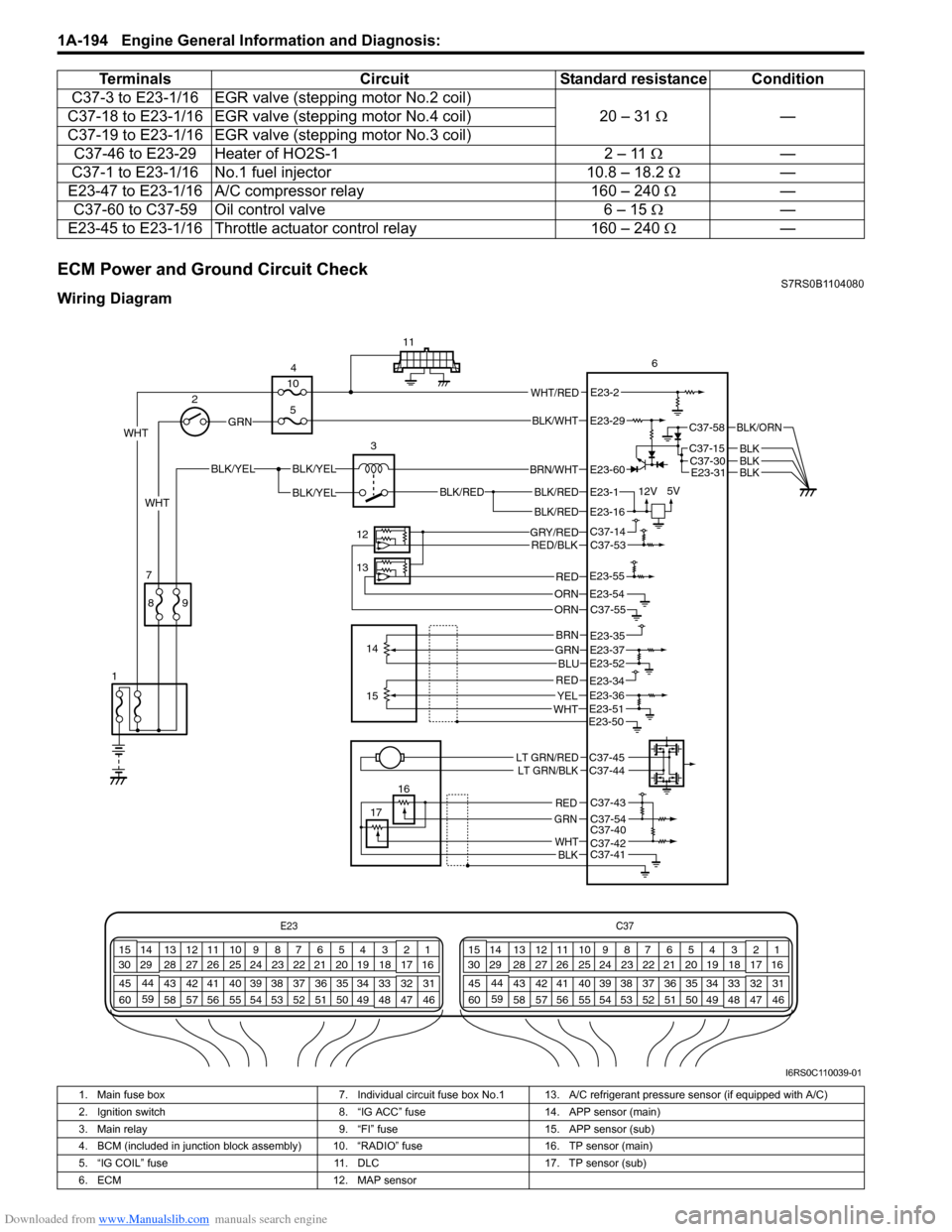
ECM Power and Ground Circuit CheckS7RS0B1104080
Wiring DiagramC37-3 to E23-1/16 EGR valve
(stepping motor No.2 coil)
20 – 31 Ω —
C37-18 to E23-1/16 EGR valv e (stepping motor No.4 coil)
C37-19 to E23-1/16 EGR valv e (stepping motor No.3 coil)
C37-46 to E23-29 Heater of HO2S-1 2 – 11 Ω—
C37-1 to E23-1/16 No.1 fuel injector 10.8 – 18.2 Ω —
E23-47 to E23-1/16 A/C compressor relay 160 – 240 Ω —
C37-60 to C37-59 Oil control valve 6 – 15 Ω —
E23-45 to E23-1/16 Throttle actuator control relay 160 – 240 Ω —
Terminals
CircuitStandard resistance Condition
E23 C37
34
1819
567
1011
17
20
47 46
495051
2122
52 16
25 9
24
14
29
55
57 54 53
59
60 58 2
262728
15
30
56 4832 31
34353637
40
42 39 38
44
45 43 41 331
1213
238
34
1819
567
1011
17
20
47 46
495051
2122
52 16
25 9
24
14
29
55
57 54 53
59
60 58 2
262728
15
30
56 4832 31
34353637
40
42 39 38
44
45 43 41 331
1213
238
BLK/RED
BLK/REDBLK/RED
BLK/YELBLK/YEL
BLK/YEL
GRN
BRN/WHT
12V
5VE23-1
E23-60
E23-16
WHT 2
4
11
6
3
12
13 14
7
1
16
17
89
15
10
5
WHT/REDE23-2
C37-58
C37-15C37-30
BLK/ORN
BLKBLKE23-31BLK
WHT
GRY/REDRED/BLK
ORN
C37-14C37-53
C37-55E23-54
REDE23-55
GRNBRN
BLU
REDYELWHT
E23-35E23-37E23-52
E23-51
E23-34E23-36
E23-50
LT GRN/REDLT GRN/BLKC37-45C37-44
C37-43
C37-54C37-40C37-42C37-41
RED
GRN
WHTBLK
ORN
BLK/WHTE23-29
I6RS0C110039-01
1. Main fuse box 7. Individual circuit fuse box No.1 13. A/C refrigerant pressure sensor (if equipped with A/C)
2. Ignition switch 8. “IG ACC” fuse14. APP sensor (main)
3. Main relay 9. “FI” fuse15. APP sensor (sub)
4. BCM (included in junction block assembly) 10. “RADIO” fuse 16. TP sensor (main)
5. “IG COIL” fuse 11. DLC17. TP sensor (sub)
6. ECM 12. MAP sensor
Page 279 of 1496
Downloaded from www.Manualslib.com manuals search engine Engine Electrical Devices: 1C-7
Installation
Reverse removal procedure noting the following.
• Clean mating surfaces of ECT sensor and thermostat case.
• Check O-ring for damage and replace, if necessary.
• Tighten ECT sensor (1) to specified torque.
Tightening torque
ECT sensor (a): 15 N·m (1.5 kgf-m, 11.0 lb-ft)
• Connect connector to ECT sensor securely.
• Refill coolant referring to “Cooling System Flush and
Refill in Section 1F”.
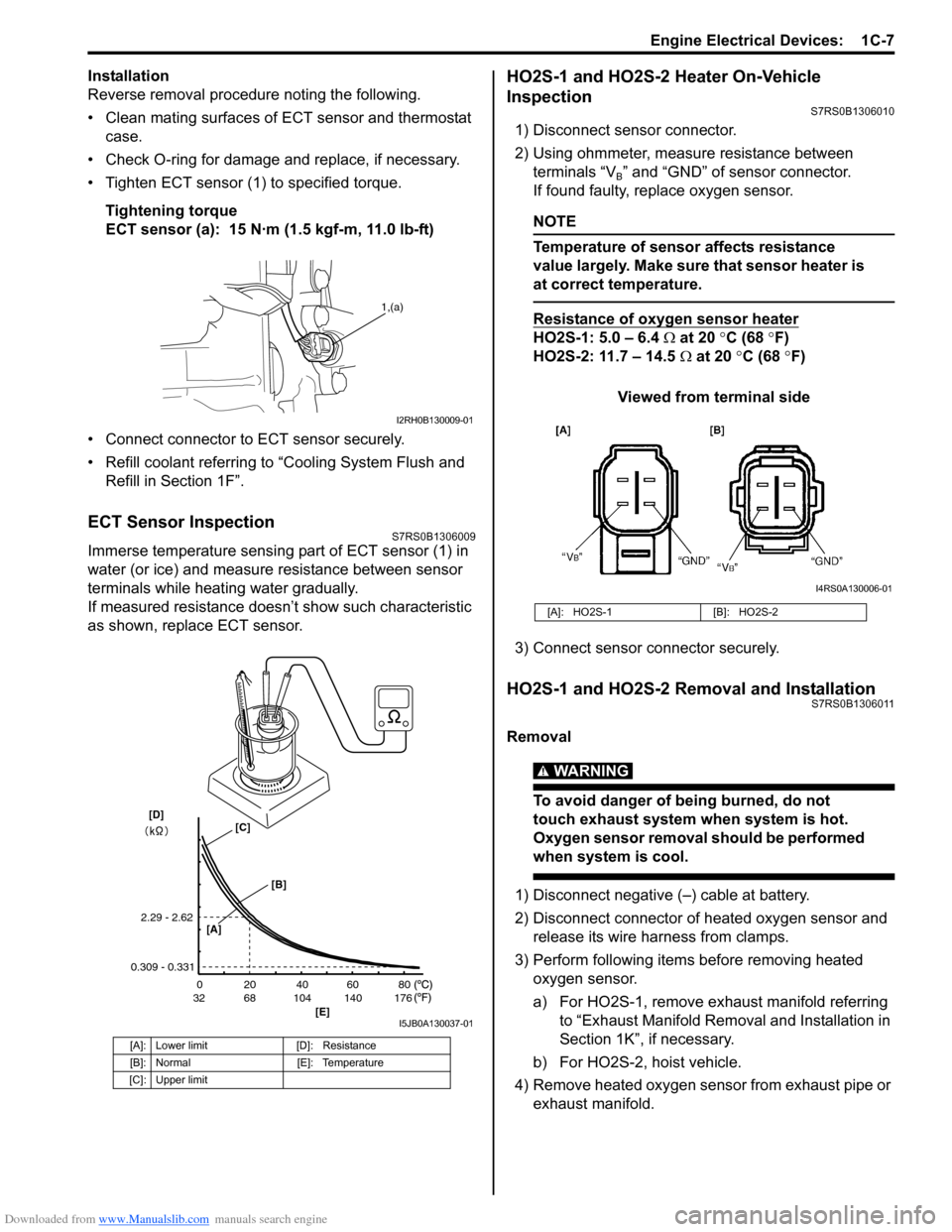
ECT Sensor InspectionS7RS0B1306009
Immerse temperature sensing part of ECT sensor (1) in
water (or ice) and measure resistance between sensor
terminals while heating water gradually.
If measured resistance doesn’t show such characteristic
as shown, replace ECT sensor.
HO2S-1 and HO2S-2 Heater On-Vehicle
Inspection
S7RS0B1306010
1) Disconnect sensor connector.
2) Using ohmmeter, measure resistance between terminals “V
B” and “GND” of sensor connector.
If found faulty, replace oxygen sensor.
NOTE
Temperature of sensor affects resistance
value largely. Make sure that sensor heater is
at correct temperature.
Resistance of oxygen sensor heater
HO2S-1: 5.0 – 6.4 Ω at 20 °C (68 °F)
HO2S-2: 11.7 – 14.5 Ω at 20 °C (68 °F)
Viewed from terminal side
3) Connect sensor co nnector securely.
HO2S-1 and HO2S-2 Removal and InstallationS7RS0B1306011
Removal
WARNING!
To avoid danger of being burned, do not
touch exhaust system when system is hot.
Oxygen sensor removal should be performed
when system is cool.
1) Disconnect negative (–) cable at battery.
2) Disconnect connector of heated oxygen sensor and
release its wire harness from clamps.
3) Perform following items before removing heated oxygen sensor.
a) For HO2S-1, remove exhaust manifold referring to “Exhaust Manifold Remo val and Installation in
Section 1K”, if necessary.
b) For HO2S-2, hoist vehicle.
4) Remove heated oxygen sensor from exhaust pipe or exhaust manifold.
[A]: Lower limit [D]: Resistance
[B]: Normal [E]: Temperature
[C]: Upper limit
1,(a)
I2RH0B130009-01
20
0
68
32 104 140 176 40 60 80
[E]
2.29 - 2.62
0.309 - 0.331
[A]
[B]
[C][D]
I5JB0A130037-01
[A]: HO2S-1 [B]: HO2S-2
I4RS0A130006-01