Page 1210 of 1496

Downloaded from www.Manualslib.com manuals search engine 9A-39 Wiring Systems:
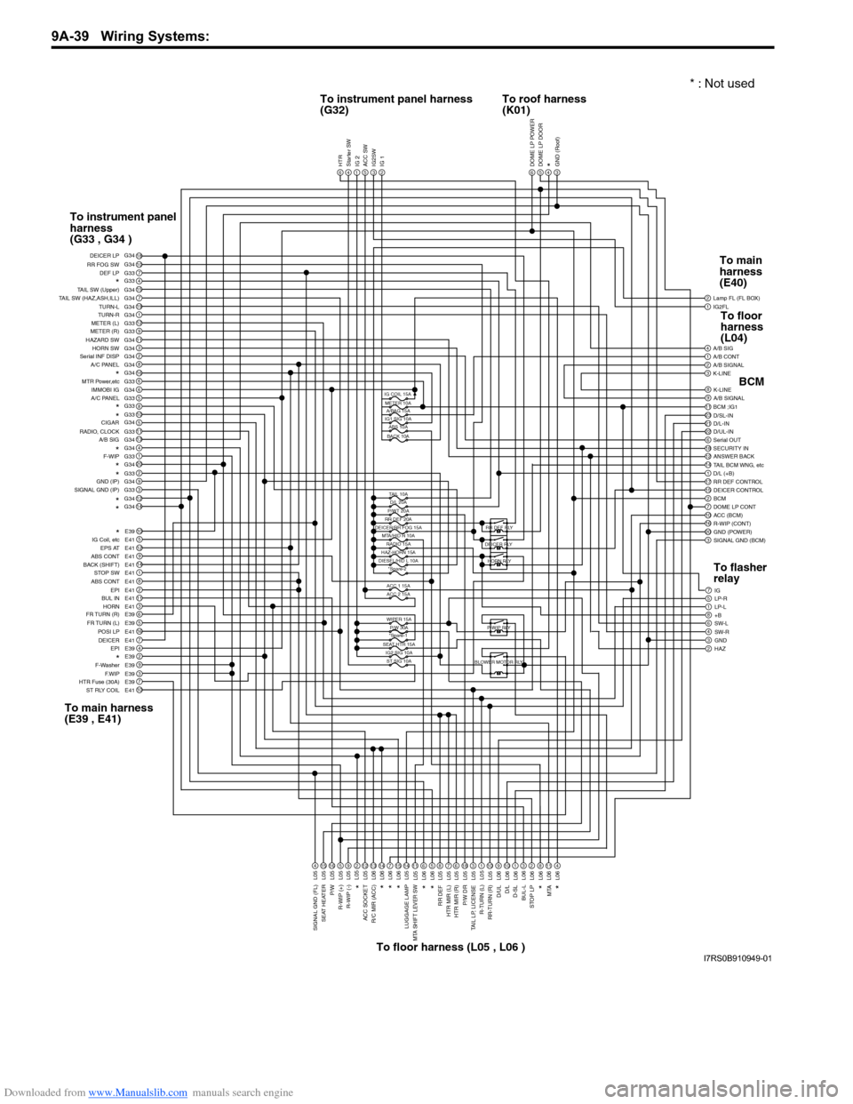
1IG2FL2
6
Lamp FL (FL BOX)
1A/B CONT4A/B SIG
3K-LINE2A/B SIGNAL
9A/B SIGNAL8K-LINE
2311BCM ;IG1
22D/UL-IN21D/L-IN D/SL-IN
18SECURITY IN6Serial OUT
14TAIL BCM WNG, etc12ANSWER BACK
17RR DEF CONTROL1D/L (+B)
2BCM15DEICER CONTROL
10ACC (BCM)7DOME LP CONT
20GND (POWER)16R-WIP (CONT)
3SIGNAL GND (BCM)
7IG
1LP-L5LP-R
8+B6SW-L
3GND4SW-R
2HAZ
DOME LP POWER5DOME LP DOOR4*3GND (Roof)6HTR4Starter SW1IG 25ACC SW3IG2SW2IG 1
18107G33415G347G3419G341G3412G339G3311G343G342G348G34166G336G345G33810511G3313G344G341G3320G342G339G343G3312G3414G34
10E395E4112E419E4114E411E418E412E4111E413E416E395E3916E417E414E392E399E393E397E3910E41
DEF LP
RR FOG SW DEICER LP
*TAIL SW (Upper)
TAIL SW (HAZ,ASH,ILL) TURN-L
TURN-R
METER (L)
METER (R)
HAZARD SW HORN SW
Serial INF DISP
A/C PANEL
*MTR Power,etc
IMMOBI IG
A/C PANEL
*
*
RADIO, CLOCK
A/B SIGCIGAR
*F-WIP*
*GND (IP)
SIGNAL GND (IP)
*
*
*
IG Coil, etc EPS AT
ABS CONT
BACK (SHIFT) STOP SW
ABS CONT EPI
BUL IN
HORN
FR TURN (R)
FR TURN (L) POSI LP
EPI
DEICER
*F-Washer
F.WIP
HTR Fuse (30A)
ST RLY COIL
4L0515L0516L055L059L05212L0513L0614L067L0615L0614L0511L056L065L068L057L056L0518L053L051L0510L059L0610L061L063L062L068L0611L064L06
SIGNAL GND (FL)
SEAT HEATER
P/W
R-WIP (+) R-WIP (-)*
ACC SOCKET
R/C MIR (ACC)
*
*
*
LUGGAGE LAMPMTA SHIFT LEVER SW
*
*
RR DEF
HTR MIR (L)
HTR MIR (R)
P/W DR
TAIL LP, LICENSE
R-TURN (L)
RR-TURN (R)
D/ULD/L
D-SL
BUL-L
STOP LP
MTA
*
*
IG COIL 15AMETER 10A A/BAG 15A
IG1 SIG 10A ABS 10A
BACK 10A
TAIL 10AD/L 20A
P/WT 20A
RR DEF 20A
DEICER/RR FOG 15A
MTA/HID R 10A
ACC 1 15A
ACC 2 15A
WIPER 15A P/W 30A
*Spare-1
SEAT HTR 15A IG2 SIG 10AST SIG 10A
HAZ-HORN 15A
DIESEL/HID L 10A *Spare-2 RR DEF RLY
DEICER RLY HORN RLY
P-WIP RLY
BLOWER MOTOR RLY
G34 G34
G33
G34
G33
G34 G33
L05
RADIO 15A
To instrument panel harness
(G32) To roof harness
(K01)
To instrument panel
harness
(G33 , G34 )
To main harness
(E39 , E41) To floor harness (L05 , L06 ) To main
harness
(E40)
BCM
To flasher
relay To floor
harness
(L04)
* : Not used
I7RS0B910949-01
Page 1215 of 1496
Downloaded from www.Manualslib.com manuals search engine Wiring Systems: 9A-44
ESP® is a registered trademark of Daimler Chrysler AG.
BCM (J/B side connector)
34
1
2 5
15
14
12
13
10
11
9
8
6
7
17
161821 22
19
20
23
1234578 11 6
12
91034 6 52
1
G33
G32
G34
10
11 12 13 14 15 16 17 18 19 123456789
20
345612K01
23414
3
561214
11
10 157
2113 16
98
6
5
4
3
2
1
7
11
10
9
8
15
14
13
12 16
L04
L06
E41
21
12 34 5 6 78 9
15 16 17 18
1110 12 13 14
1
234
5 678 910
E39
L05
E40
E39 E41E40
BCM G34G33G32 K01 L04 L05 L06J/B
9
3
3
20
3
4
(Continued)
GND (IP)
POWER GND
BCM SIG GND GND (Roof)
GND (POWER)
SIGNAL
GND (FL) SIGNAL
GND (IP) SIGNAL
GND (BCM)
4
4
10
Starter SW
ST RLY COIL
ST SIG 10A36
Individual circuit fuse box No.2
(In J/B)
7
6
BLOWER MOTOR RLY
HTR
HTR Fuse
(30A)
IG2 SIG 10A38
5
7
DOME LP DOOR
DOME LP CONT
21
22
10
9
D/L-IN D/L
D/UL-IND/UL
3
5
2 1
Connector No. / Terminal No.
56
I7RS0B910950-01
Page 1217 of 1496
Downloaded from www.Manualslib.com manuals search engine Wiring Systems: 9A-46
A-1 Cranking System Circuit DiagramS7RS0B910E002
Starting motorrelay
W
"A-5"
ECM
P
R N D2LTransaxle
range sensor
C28
E741
4
E31
C231C241
Starting motor
MOFF ON
BLK
1
BLK/GRY
C311
Battery
E24
C361
RED
Individual circuit
fuse box (No.1)
10
30A
36
10A
WHTWHT
M/T
IF EQPD
E24
C361
J/B
A/T
E4110
13
2
4
RED/WHT
2 ST MOT
ST SIG
YEL/GRN
YG
"A-5"
ECM
GRN/WHT
G212
YEL/GRN
YEL/GRN
YEL
YEL/GRN
YEL
YEL
G324
+B1
LOCK
ACC
ON
ST ACC IG1 IG2
STOUT
IN
+B2
21CPP
switch
2
I7RS0B910940-01
Page 1224 of 1496
Downloaded from www.Manualslib.com manuals search engine 9A-53 Wiring Systems:
J/C
E43
J/C
G16
DLC
G20
G375
E469
E38
G3614
C36 E2415
BLK/ORN
BLK/ORN
BLK/ORN
4
BLK
11
J/C
G15
5
4
516
WHT/RED
C37
GRN/YELGRN/WHT
5 6
YG
BRN
B
P/S
Cont.M
4
"F-3"
25
A
A D
E
AA
PPL/WHT
PPL/WHT
PPL/WHT
PPL/WHT
YEL/GRNWHT/RED
BLK
9
A
PPL
E42
PPLJ/C
ECM
E394
J/B15A RADIO
40
E23
E23
YEL/BLKYEL/REDRED/BLU
13
282620
BLK
2C37
M/T
A/T
48
W
WHT
30
GYGW
BRN/WHTBLU/YEL
28
8
BWBY
IG COIL
#1 Generator
IG COIL
#2
(CAN) "A-3""A-2"
Audio
"G-1"
GRN/WHT
P
7
BCM
Starting motor relay
"A-1"
Transaxle
range sensor
YG"A-1"
ICM
"A-7"
P/S
Cont.M
"F-3"YBYRRBGW"D-7"
Brake light switch
"A-1"Starting motor
PW
PW
G335
WHT/BLKRED/BLK
RBWB
"A-8"
14
6
BCM
A
J/C
E43
APPL
P
E42C
IF EQPD IF EQPD
IF EQPD
I6RS0C910913-03
Page 1243 of 1496

Downloaded from www.Manualslib.com manuals search engine Wiring Systems: 9A-72
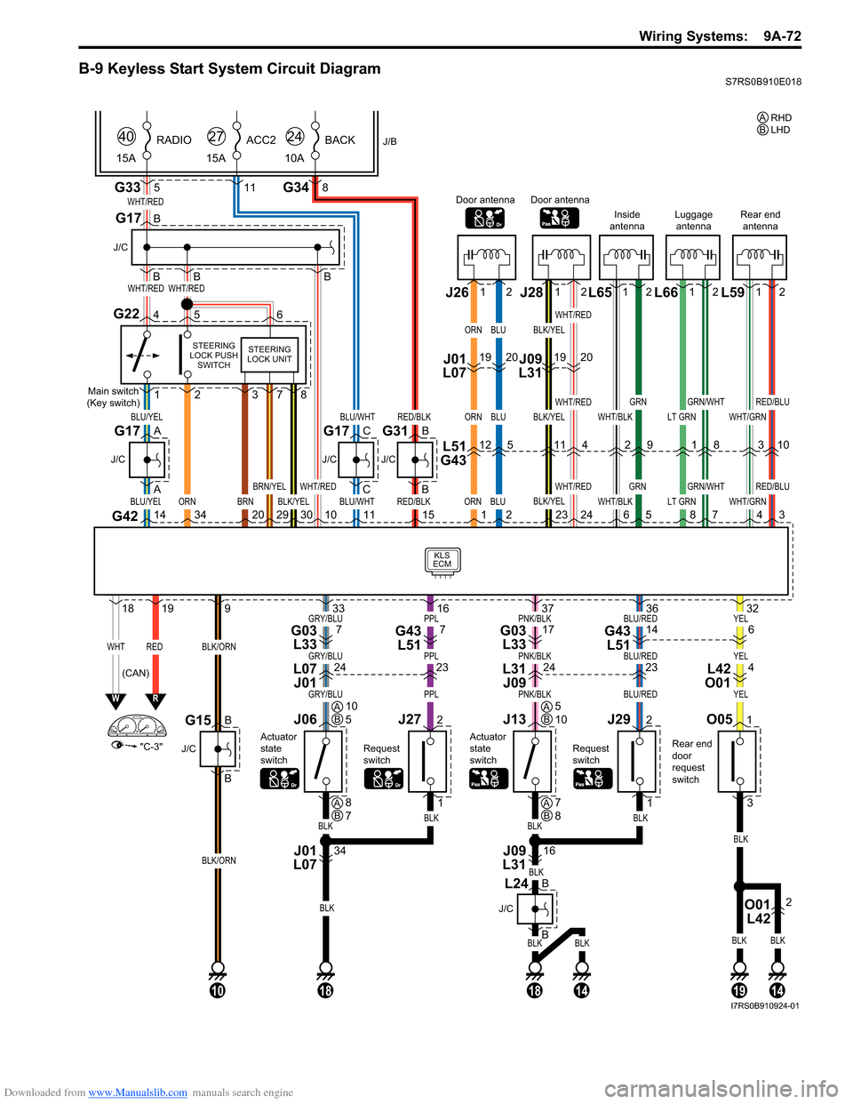
B-9 Keyless Start System Circuit DiagramS7RS0B910E018
BLKBLK
BLK
BLKBLK
YELBLU/REDPNK/BLKPPLGRY/BLU
YELBLU/REDPNK/BLKPPLGRY/BLU
YELBLU/REDPNK/BLKPPLGRY/BLU
G33
KLS
ECM
WHT/RED
WHT/REDWHT/RED
BLU/YEL
WHTRED
ORN
BLU/YEL
"C-3"
WR
G42143420
1819
BLK/ORN
BLK/ORN
9
5
J/B
15A RADIO
40
G348
10A
BACK
24
11
15A
ACC2
27
B
B
B
J/C
G17
B
A
A
J/C
BLU/WHT
BLU/WHT
C
C
J/C
G17
Main switch
(Key switch)
STEERING
LOCK PUSH SWITCH
G22456
1
O051
3
2
BRN29
BRN/YEL
301011RED/BLK
RED/BLK
B
B
J/C
Rear end
door
request
switch
G31
15ORN
ORN
ORN
1BLK/YEL
WHT/RED
378
STEERING
LOCK UNIT
Door antenna
L51
G4312
J01
L07 J261912
BLU
BLU
BLU
2
5
20
WHT/BLK
WHT/BLK6
Inside
antenna
2
12
GRN
GRN
5
9
LT GRN
LT GRN8
Luggage antenna
1
12
GRN/WHT
GRN/WHT
7
8
BLK/YEL
BLK/YEL
BLK/YEL
23
Door antenna
11
J09
L31 J28 L65 L66
WHT/GRN
WHT/GRN4
Rear end
antenna
3
12
RED/BLU
RED/BLU
3
10
L59
1912
WHT/RED
WHT/RED
WHT/RED
24
4
20
G17
B
B
J/C
G15
10
BLK
BLKBLK
32
J292
1
Request
switch
36
1914
J13
Actuator
state
switch
O01 L422
16
BLK
37
1814
J09
L31
J272
1
Request
switch
16
J06
Actuator
state
switch
34
BLK
BLK
33
18
J01
L07
(CAN) RHD
A
LHD
B
AB10
5AB5
10
AB8
7AB7
8
614G43
L5117G03 L337G43 L517G03 L33
423242324L42
O01
L31
J09
L07
J01
B
J/C
B
L24
I7RS0B910924-01
Page 1297 of 1496

Downloaded from www.Manualslib.com manuals search engine Instrumentation / Driver Info. / Horn: 9C-2
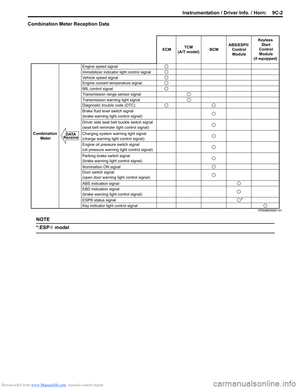
Combination Meter Reception Data
NOTE
*:ESP® model
ECM BCM
Keyless
Start
Control Module
(if equipped)
Combination Meter
TCM
(A/T model)
Engine speed signal
Immobilizer indicator light control signal
Vehicle speed signal
Engine coolant temperature signal
MIL control signal
Transmission range sensor signal
Transmission warning light signal
Diagnostic trouble code (DTC)
Brake fluid level switch signal
(brake warning light control signal)
Driver side seat belt buckle switch signal
(seat belt reminder light control signal)
Charging system warning light signal
(charge warning light control signal)
Engine oil pressure switch signal
(oil pressure warning light control signal)
Parking brake switch signal
(brake warning light control signal)
Illumination ON signal
Door switch signal
(open door warning light control signal)
ABS indication signal
EBD indication signal
(brake warning light control signal)
Key indicator light control signal ABS/ESP®
ControlModule
DATA
Receive
*
ESP® status signal
I7RS0B930001-01
Page 1299 of 1496
Downloaded from www.Manualslib.com manuals search engine Instrumentation / Driver Info. / Horn: 9C-4
Schematic and Routing Diagram
Combination Meter Circuit DiagramS7RS0B9302001
16
15
14
13
G28-5
5
6
3
G28-26
7
G28-2219
G28-2520
G28-17
12
10 11
21
9
17
G28-304G28-29
18
G28-16
G28-9
G28-10G28-8 G28-7
1
2 8
G38-31
G38-32
I7RS0B930002-01
1. Keyless start control module
8. CAN driver 15. Fuel meter
2. BCM 9. Interface circuit 16. ECT meter
3. SDM 10. Power supply 17. Stepper motor and LED output driver
4. Fuel level sensor 11. CPU 18. A/T shift position indicator (“P”, “R”, “N”, “D”, “3”, “2”, and “L”)
5. RADIO fuse 12. ODO-TRIP 19. Combination switch (high beam)
6. METER fuse 13. Tachometer 20. P/S control module
7. Combination switch 14. Speedometer 21. Combination meter
Page 1309 of 1496

Downloaded from www.Manualslib.com manuals search engine Instrumentation / Driver Info. / Horn: 9C-14
Navigation Symptom Diagnosis (If Equipped)S7RS0B9304019
Repair Instructions
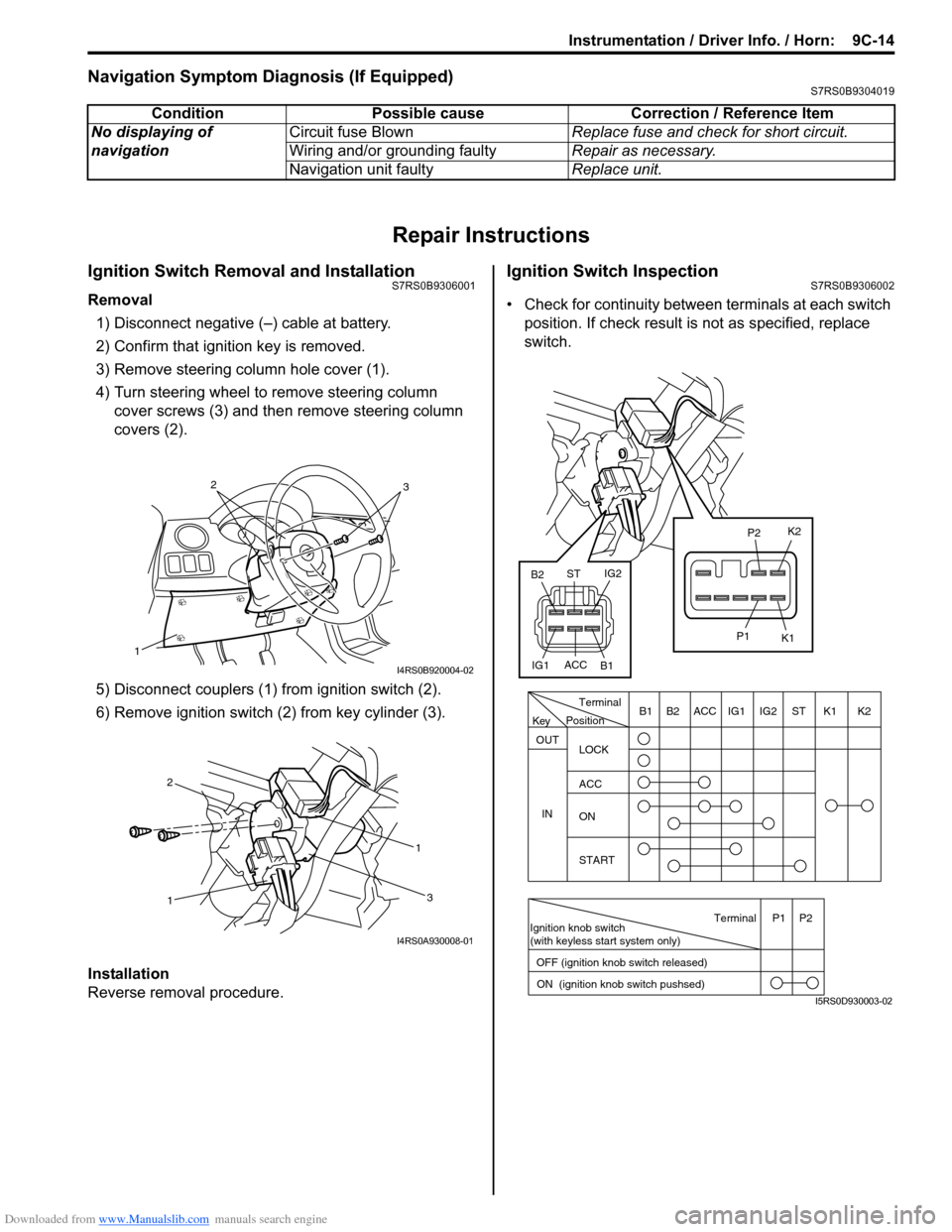
Ignition Switch Removal and InstallationS7RS0B9306001
Removal
1) Disconnect negative (–) cable at battery.
2) Confirm that ignition key is removed.
3) Remove steering column hole cover (1).
4) Turn steering wheel to remove steering column cover screws (3) and then remove steering column
covers (2).
5) Disconnect couplers (1) from ignition switch (2).
6) Remove ignition switch (2) from key cylinder (3).
Installation
Reverse removal procedure.
Ignition Switch InspectionS7RS0B9306002
• Check for continuity between terminals at each switch
position. If check result is not as specified, replace
switch.
Condition Possible cause Correction / Reference Item
No displaying of
navigation Circuit fuse Blown
Replace fuse and check for short circuit.
Wiring and/or grounding faulty Repair as necessary.
Navigation unit faulty Replace unit.
1
32
I4RS0B920004-02
1 1
2
3
I4RS0A930008-01
PositionTerminal
LOCK
ACC
ON
START
OUT
INK2K1ST
IG2
IG1
ACC
B1 B2
Ignition knob switch
(with keyless start system only)
ACC
IG1 IG2
ST
B2
B1 K2
K1
P2
P1
Terminal
OFF (ignition knob switch released) ON (ignition knob switch pushsed)P1 P2
Key
I5RS0D930003-02