2006 SUZUKI SWIFT Front
[x] Cancel search: FrontPage 1402 of 1496
Downloaded from www.Manualslib.com manuals search engine 10-ii Table of Contents
DTC P1615: ID Code Does Not Registered (Vehicle equipped with keyless start system
only) ................................................................10C-9
DTC P1616: Different Registration ID Codes (Vehicle equipped with keyless start system
only) ..............................................................10C-10
DTC P1618: CAN Communication Error (Reception Error for Keyless Start Control
Module) (Vehicle equipped with keyless
start system only) ..........................................10C-11
DTC P1621: Immobilizer Communication Line Error ......................................................10C-12
DTC P1622: EEPROM Reading / Writing Error ..............................................................10C-13
DTC P1623: Unregistered Transponder .........10C-13
DTC P1625: Immobilizer An tenna Error..........10C-14
DTC P1636: Immobilizer Information Registration Failure .......................................10C-14
DTC P1638: Immobilizer Information Mismatched ...................................................10C-15
Inspection of Immobilizer Control Module (ICM) and Its Circuit ....... ...............................10C-16
Repair Instructions ........... ...............................10C-18
Immobilizer Control Mo dule (ICM) Removal
and Installation ..............................................10C-18
Registration of the Ignition Key .......................10C-18
Procedure after ECM Replacement ................10C-18
Special Tools and Equipmen t .........................10C-19
Special Tool ....................................................10C-19
Keyless Start System ....... ......................10E-1
General Description ........................................... 10E-1
Keyless Start System Description ..................... 10E-1
Parts and Functions .......................................... 10E-2
Keyless Engine Start Function .......................... 10E-3
Door Lock Function of Keyless Start System .... 10E-4
Operation Area of Remote Controller................ 10E-5
Alarm Function .................................................. 10E-6
CAN Communication System Description......... 10E-6
Schematic and Routing Diagram ...................... 10E-7 Keyless Start System El ectric Wiring Circuit
Diagram .......................................................... 10E-7
Diagnostic Information and Procedures .......... 10E-8 Precautions in Diagnosing Troubles ................. 10E-8
Self-Diagnosis Function .................................... 10E-8
Keyless Start System Diagn osis Introduction ... 10E-8 Keyless Start System Chec
k ............................. 10E-8
Customer Questionnaire (E xample) .................. 10E-9
Key Indicator Lamp Check .............................. 10E-10
DTC Check...................................................... 10E-10
DTC Table ....................................................... 10E-11
DTC Clearance ............................................... 10E-12
Keyless Start System Symp tom Diagnosis ..... 10E-12
Keyless Start System Operation Inspection .... 10E-13
Door Lock Operation (Keyless Start System) . 10E-14
Inspection of Keyless Start Control Module and Its Circuits .............................................. 10E-14
No DTC Detection After Performing DTC Check ............................................................ 10E-18
Key Indicator Lamp Circuit Check (Key indicator lamp doesn’t light when ignition
knob switch is pushed.) ................................. 10E-20
Keyless Start Control Module Power and Ground Circuit Check .................................... 10E-22
DTC No. 11: Communi cation Error with
Steering Lock Unit ......................................... 10E-23
DTC No. 13 / No. 14: Release Signal Error from Steering Lock Unit / Steering Lock Unit
Malfunction .................................................... 10E-24
DTC No. 21 / No. 22: Internal Error of Keyless Start Control Module (EEPROM reading
error) / (EEPROM writing error) ............ ........ 10E-24
DTC No. 31: Lost Commun ication with BCM .. 10E-25
DTC No. 33: Control Module Communication
Bus Off .......................................................... 10E-27
DTC No. 51 / No. 52 / No. 53: Driver Side / Passenger Side / Rear End Door Request
Switch Failure................................................ 10E-28
Repair Instructions ............ .............................. 10E-30
Antennas and Request Switches Removal and Installation .............................................. 10E-30
Front Door (Driver and Passenger Side), Rear End Door Request Switch Inspection............ 10E-31
Steering Lock Unit Removal and Installation .. 10E-31
Steering Lock Unit Inspection ......................... 10E-31
Front Door Lock Switch In spection ................. 10E-31
Keyless Start Control Module Removal and Installation ..................................................... 10E-32
Remote Controller Inspection.......................... 10E-32
Replacement of Remote Controller Battery .... 10E-32
Registration Procedure for Remote Controller
ID Code ......................................................... 10E-33
Page 1423 of 1496
Downloaded from www.Manualslib.com manuals search engine Body Electrical Control System: 10B-20
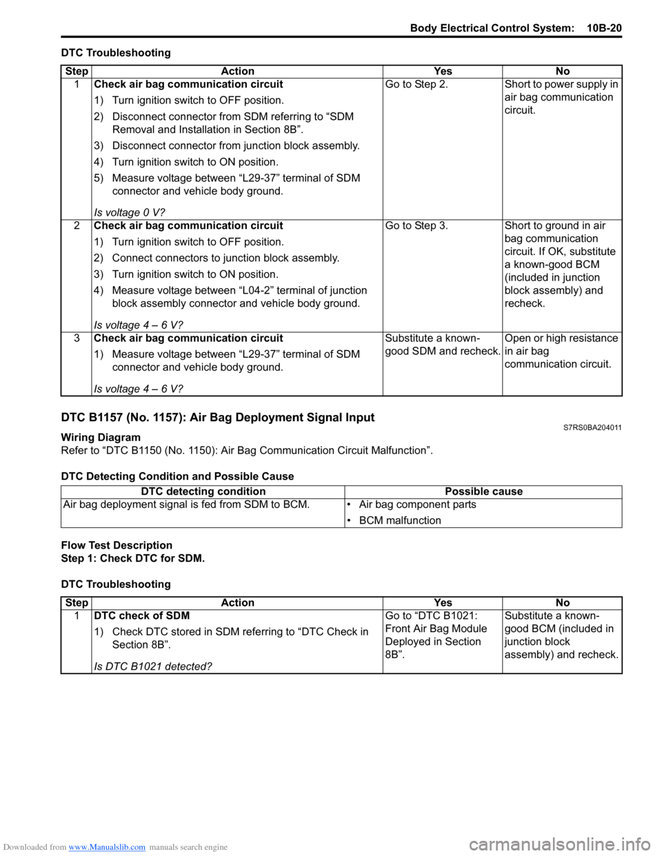
DTC Troubleshooting
DTC B1157 (No. 1157): Air Bag Deployment Signal InputS7RS0BA204011
Wiring Diagram
Refer to “DTC B1150 (No. 1150): Air Bag Communication Circuit Malfunction”.
DTC Detecting Conditi on and Possible Cause
Flow Test Description
Step 1: Check DTC for SDM.
DTC Troubleshooting Step Action Yes No
1 Check air bag communication circuit
1) Turn ignition switch to OFF position.
2) Disconnect connector from SDM referring to “SDM
Removal and Installation in Section 8B”.
3) Disconnect connector from junction block assembly.
4) Turn ignition switch to ON position.
5) Measure voltage between “L29-37” terminal of SDM connector and vehicle body ground.
Is voltage 0 V? Go to Step 2. Short to power supply in
air bag communication
circuit.
2 Check air bag communication circuit
1) Turn ignition switch to OFF position.
2) Connect connectors to junction block assembly.
3) Turn ignition switch to ON position.
4) Measure voltage between “L04-2” terminal of junction
block assembly connector and vehicle body ground.
Is voltage 4 – 6 V? Go to Step 3.
Short to ground in air
bag communication
circuit. If OK, substitute
a known-good BCM
(included in junction
block assembly) and
recheck.
3 Check air bag communication circuit
1) Measure voltage between “L29-37” terminal of SDM
connector and vehicle body ground.
Is voltage 4 – 6 V? Substitute a known-
good SDM and recheck.
Open or high resistance
in air bag
communication circuit.
DTC detecting condition
Possible cause
Air bag deployment signal is fed from SDM to BCM. • Air bag component parts
• BCM malfunction
StepAction YesNo
1 DTC check of SDM
1) Check DTC stored in SDM re ferring to “DTC Check in
Section 8B”.
Is DTC B1021 detected? Go to “DTC B1021:
Front Air Bag Module
Deployed in Section
8B”.
Substitute a known-
good BCM (included in
junction block
assembly) and recheck.
Page 1466 of 1496
Downloaded from www.Manualslib.com manuals search engine 10E-4 Keyless Start System:
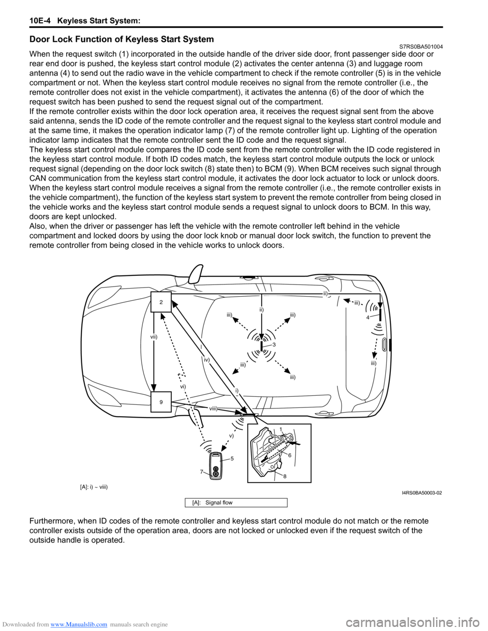
Door Lock Function of Keyless Start SystemS7RS0BA501004
When the request switch (1) incorporated in the outside handle of the driver side door, front passenger side door or
rear end door is pushed, the keyless start control modul e (2) activates the center antenna (3) and luggage room
antenna (4) to send out the radio wave in the vehicle compartm ent to check if the remote controller (5) is in the vehicle
compartment or not. When the keyless start control module receives no signal from the remote controller (i.e., the
remote controller does not exist in the vehicle compartment) , it activates the antenna (6) of the door of which the
request switch has been pushed to send the request signal out of the compartment.
If the remote controller exists within the door lock operati on area, it receives the request signal sent from the above
said antenna, sends the ID code of the remote controller and the request signal to the keyless start control module and
at the same time, it makes the operatio n indicator lamp (7) of the remote controller light up. Lighting of the operation
indicator lamp indicates that the remote controller sent the ID code and the request signal.
The keyless start control module compares the ID code sent from the remote controller with the ID code registered in
the keyless start control module. If both ID codes match, the keyless start control module outputs the lock or unlock
request signal (depending on the door lock switch (8) stat e then) to BCM (9). When BCM receives such signal through
CAN communication from the keyless start control module, it activates the door lock actuator to lock or unlock doors.
When the keyless start control module receiv es a signal from the remote controller (i.e., the remote controller exists in
the vehicle compartment), the function of the keyless start system to prevent the remote controller from being closed in
the vehicle works and the keyless start control module sends a request signal to unlock doors to BCM. In this way,
doors are kept unlocked.
Also, when the driver or passenger has left the vehicl e with the remote controller left behind in the vehicle
compartment and locked doors by using the door lock knob or manual door lock switch, the function to prevent the
remote controller from being closed in the vehicle works to unlock doors.
Furthermore, when ID codes of the remote controller and keyless start control module do not match or the remote
controller exists outside of the operation area, doors are not locked or unlocked even if the request switch of the
outside handle is operated.
9 2
vi)
v)
vii) iv)
i) ii)
iii)
iii)iii)
ii)
iii)
iii)
iii)
3
5
8
6
1 4
7
[A]: i) ~ viii)
viii)
I4RS0BA50003-02
[A]: Signal flow
Page 1467 of 1496
Downloaded from www.Manualslib.com manuals search engine Keyless Start System: 10E-5
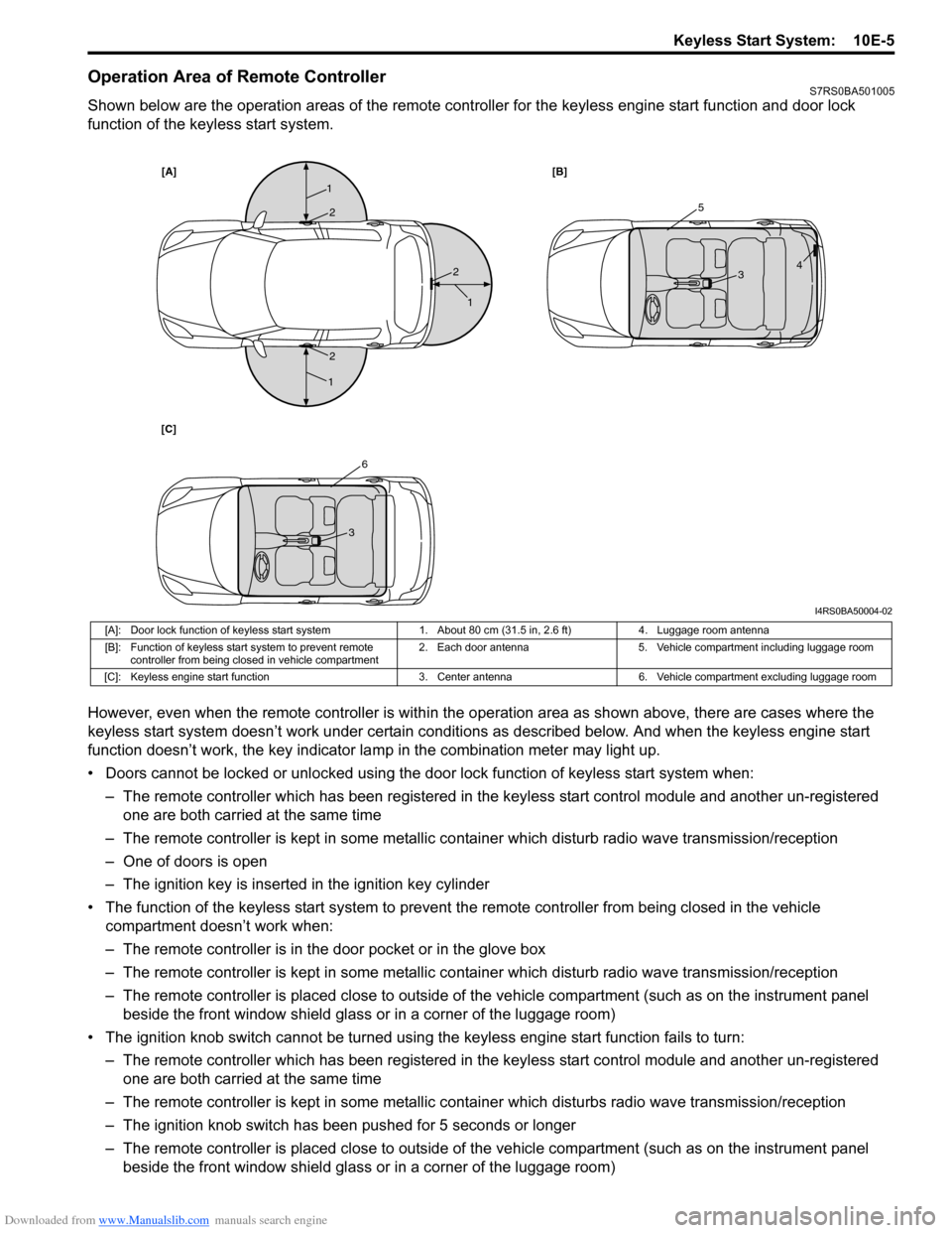
Operation Area of Remote ControllerS7RS0BA501005
Shown below are the operation areas of the remote controller for the keyless engine start function and door lock
function of the keyless start system.
However, even when the remote controller is within the operation area as shown above, there are cases where the
keyless start system doesn’t work under certain conditi ons as described below. And when the keyless engine start
function doesn’t work, the key indicator la mp in the combination meter may light up.
• Doors cannot be locked or unlocked using the doo r lock function of keyless start system when:
– The remote controller which has been registered in the keyless start control module and another un-registered one are both carried at the same time
– The remote controller is kept in some metallic co ntainer which disturb radio wave transmission/reception
– One of doors is open
– The ignition key is inserted in the ignition key cylinder
• The function of the keyless start system to prevent the remote controller from being closed in the vehicle
compartment doesn’t work when:
– The remote controller is in the door pocket or in the glove box
– The remote controller is kept in some metallic co ntainer which disturb radio wave transmission/reception
– The remote controller is placed close to outside of the vehicle compartment (such as on the instrument panel beside the front window shield glass or in a corner of the luggage room)
• The ignition knob switch cannot be turned usin g the keyless engine start function fails to turn:
– The remote controller which has been registered in the keyless start control module and another un-registered one are both carried at the same time
– The remote controller is kept in some metallic cont ainer which disturbs radio wave transmission/reception
– The ignition knob switch has been pushed for 5 seconds or longer
– The remote controller is placed close to outside of the vehicle compartment (such as on the instrument panel beside the front window shield glass or in a corner of the luggage room)
[A] [B]
[C]
1
1
1
25
6
3
3 4
2
2
I4RS0BA50004-02
[A]: Door lock function of keyless start system 1. About 80 cm (31.5 in, 2.6 ft)4. Luggage room antenna
[B]: Function of keyless start system to prevent remote controller from being closed in vehicle compartment 2. Each door antenna
5. Vehicle compartment including luggage room
[C]: Keyless engine start function 3. Center antenna6. Vehicle compartment excluding luggage room
Page 1474 of 1496
Downloaded from www.Manualslib.com manuals search engine 10E-12 Keyless Start System:
DTC ClearanceS7RS0BA504009
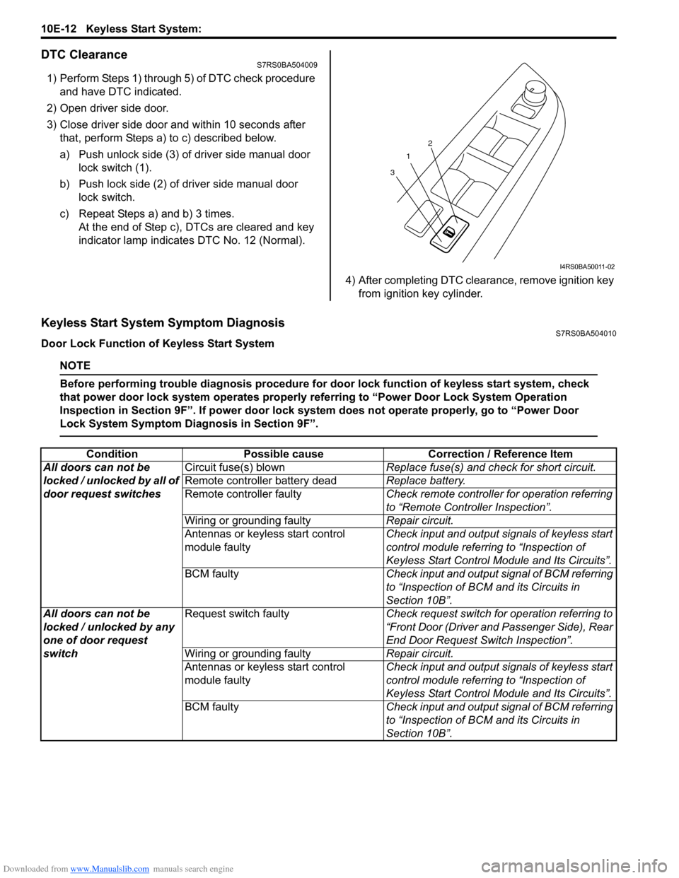
1) Perform Steps 1) through 5) of DTC check procedure and have DTC indicated.
2) Open driver side door.
3) Close driver side door and within 10 seconds after that, perform Steps a) to c) described below.
a) Push unlock side (3) of driver side manual door lock switch (1).
b) Push lock side (2) of driver side manual door lock switch.
c) Repeat Steps a) and b) 3 times. At the end of Step c), DTCs are cleared and key
indicator lamp indicates DTC No. 12 (Normal).
4) After completing DTC clearance, remove ignition key from ignition key cylinder.
Keyless Start System Symptom DiagnosisS7RS0BA504010
Door Lock Function of Keyless Start System
NOTE
Before performing trouble diagnosis procedure for door lock function of keyless start system, check
that power door lock system operates properly referring to “Power Door Lock System Operation
Inspection in Section 9F”. If power door lock system does not operate properly, go to “Power Door
Lock System Symptom Diagnosis in Section 9F”.
1
3 2
I4RS0BA50011-02
Condition
Possible cause Correction / Reference Item
All doors can not be
locked / unlocked by all of
door request switches Circuit fuse(s) blown
Replace fuse(s) and check for short circuit.
Remote controller battery dead Replace battery.
Remote controller faulty Check remote controller for operation referring
to “Remote Controller Inspection”.
Wiring or grounding faulty Repair circuit.
Antennas or keyless start control
module faulty Check input and output signals of keyless start
control module referring to “Inspection of
Keyless Start Control Mo
dule and Its Circuits”.
BCM faulty Check input and output signal of BCM referring
to “Inspection of BCM and its Circuits in
Section 10B”.
All doors can not be
locked / unlocked by any
one of door request
switch Request switch faulty
Check request switch for operation referring to
“Front Door (Driver and Passenger Side), Rear
End Door Request Switch Inspection”.
Wiring or grounding faulty Repair circuit.
Antennas or keyless start control
module faulty Check input and output signals of keyless start
control module referring to “Inspection of
Keyless Start Control Mo
dule and Its Circuits”.
BCM faulty Check input and output signal of BCM referring
to “Inspection of BCM and its Circuits in
Section 10B”.
Page 1491 of 1496
Downloaded from www.Manualslib.com manuals search engine Keyless Start System: 10E-29
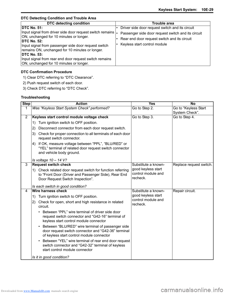
DTC Detecting Condition and Trouble Area
DTC Confirmation Procedure1) Clear DTC referring to “DTC Clearance”.
2) Push request switch of each door.
3) Check DTC referring to “DTC Check”.
Troubleshooting DTC detecting condition Trouble area
DTC No. 51:
Input signal from driver side door request switch remains
ON, unchanged for 10 minutes or longer.
DTC No. 52:
Input signal from passenger side door request switch
remains ON, unchanged for 10 minutes or longer.
DTC No. 53:
Input signal from rear end door request switch remains
ON, unchanged for 10 minutes or longer. • Driver side door request switch and its circuit
• Passenger side door request switch and its circuit
• Rear end door request switch and its circuit
• Keyless start control module
Step
Action YesNo
1 Was “Keyless Start System Check” performed? Go to Step 2.Go to “Keyless Start
System Check”.
2 Keyless start control module voltage check
1) Turn ignition switch to OFF position.
2) Disconnect connector from each door request switch.
3) Check for proper connection to all terminals of each door
request switch connector.
4) If OK, measure voltage between “PPL”, “BLU/RED” or “YEL” terminal of related door request switch connector
and vehicle body ground.
Is voltage 10 – 14 V? Go to Step 3.
Go to Step 4.
3 Request switch check
1) Check related door request switch for function referring
to “Front Door (Driver and Passenger Side), Rear End
Door Request Switch Inspection”.
Is each switch in good condition? Substitute a known-
good keyless start
control module and
recheck.
Replace request switch.
4 Wire harness check
1) Turn ignition switch to OFF position.
2) Check for open, short and high resistance in related
circuit.
• Between “PPL” wire terminal of driver side door request switch connector and “G42-16” terminal of
keyless start control module connector
• Between “BLU/RED” wire terminal of passenger side door request switch connector and “G42-36” terminal
of keyless start control module connector
• Between “YEL” wire terminal of rear end door request switch connector and “G42-32” terminal of keyless
start control module connector
Is it in good condition? Substitute a known-
good keyless start
control module and
recheck.
Repair circuit.
Page 1492 of 1496
Downloaded from www.Manualslib.com manuals search engine 10E-30 Keyless Start System:
Repair Instructions
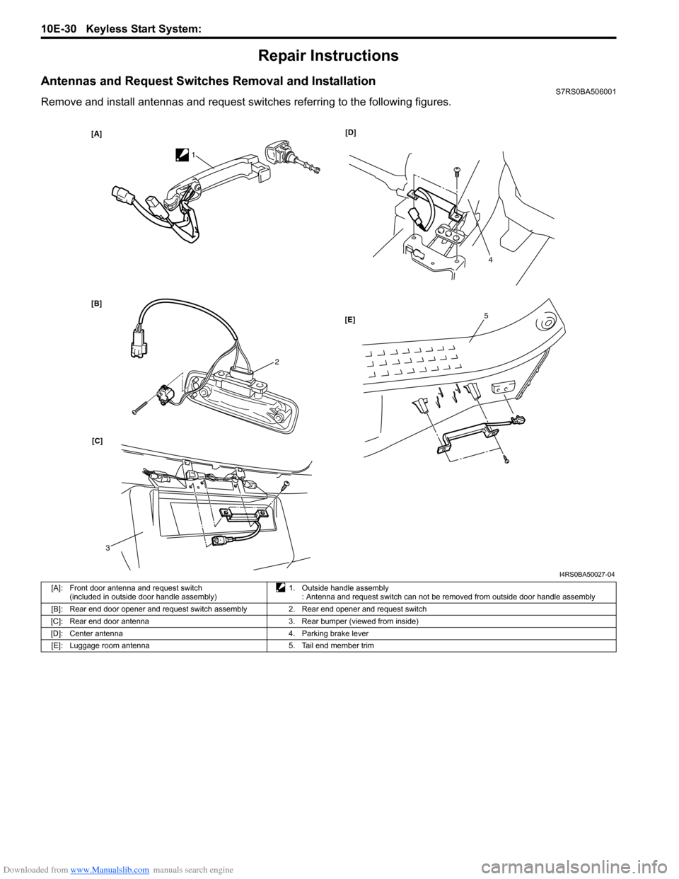
Antennas and Request Switches Removal and InstallationS7RS0BA506001
Remove and install antennas and request switches referring to the following figures.
[A]
[B][D]
[C] [E]
1
2
3
4
5
I4RS0BA50027-04
[A]: Front door antenna and request switch
(included in outside door handle assembly) 1. Outside handle assembly
: Antenna and request switch can not be removed from outside door handle assembly
[B]: Rear end door opener and request switch assembly 2. Rear end opener and request switch
[C]: Rear end door antenna 3. Rear bumper (viewed from inside)
[D]: Center antenna 4. Parking brake lever [E]: Luggage room antenna 5. Tail end member trim
Page 1493 of 1496
Downloaded from www.Manualslib.com manuals search engine Keyless Start System: 10E-31
Front Door (Driver and Passenger Side), Rear
End Door Request Switch Inspection
S7RS0BA506002
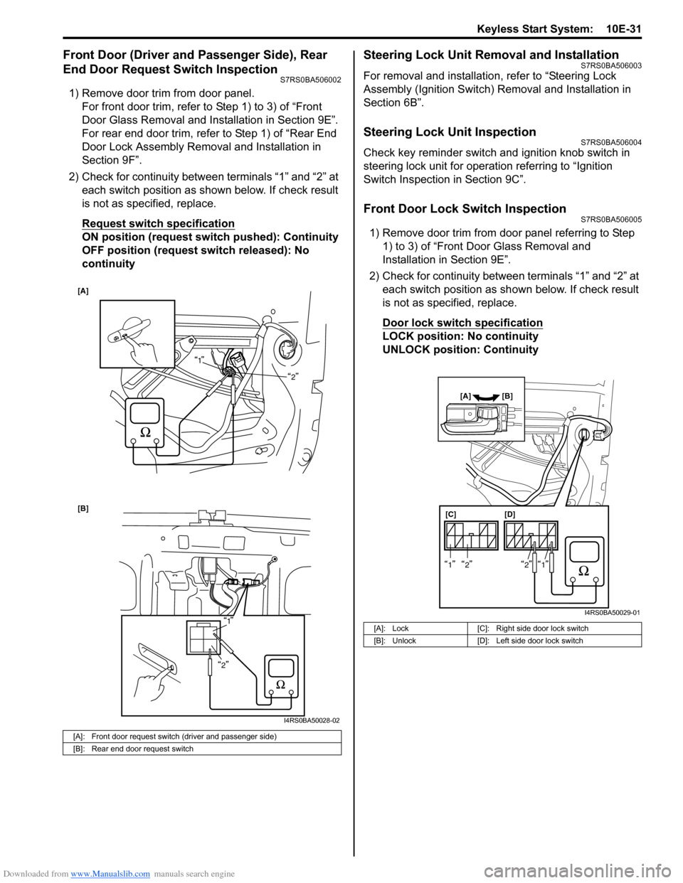
1) Remove door trim from door panel.For front door trim, refer to Step 1) to 3) of “Front
Door Glass Removal and Inst allation in Section 9E”.
For rear end door trim, refer to Step 1) of “Rear End
Door Lock Assembly Remo val and Installation in
Section 9F”.
2) Check for continuity between terminals “1” and “2” at each switch position as shown below. If check result
is not as specified, replace.
Request switch specification
ON position (request switch pushed): Continuity
OFF position (request switch released): No
continuity
Steering Lock Unit Removal and InstallationS7RS0BA506003
For removal and installation, refer to “Steering Lock
Assembly (Ignition Switch) Removal and Installation in
Section 6B”.
Steering Lock Unit InspectionS7RS0BA506004
Check key reminder switch and ignition knob switch in
steering lock unit for operation referring to “Ignition
Switch Inspection in Section 9C”.
Front Door Lock Switch InspectionS7RS0BA506005
1) Remove door trim from door panel referring to Step 1) to 3) of “Front Door Glass Removal and
Installation in Section 9E”.
2) Check for continuity between terminals “1” and “2” at each switch position as sh own below. If check result
is not as specified, replace.
Door lock switch specification
LOCK position: No continuity
UNLOCK position: Continuity
[A]: Front door request switch (driver and passenger side)
[B]: Rear end door request switch
[A]
1
2
[B]
1
2
I4RS0BA50028-02
[A]: Lock [C]: Right side door lock switch
[B]: Unlock [D]: Left side door lock switch
[C][D]
[A] [B]
1212
I4RS0BA50029-01