2006 SUZUKI SWIFT turn signal fuse
[x] Cancel search: turn signal fusePage 262 of 1496
Downloaded from www.Manualslib.com manuals search engine 1A-212 Engine General Information and Diagnosis:
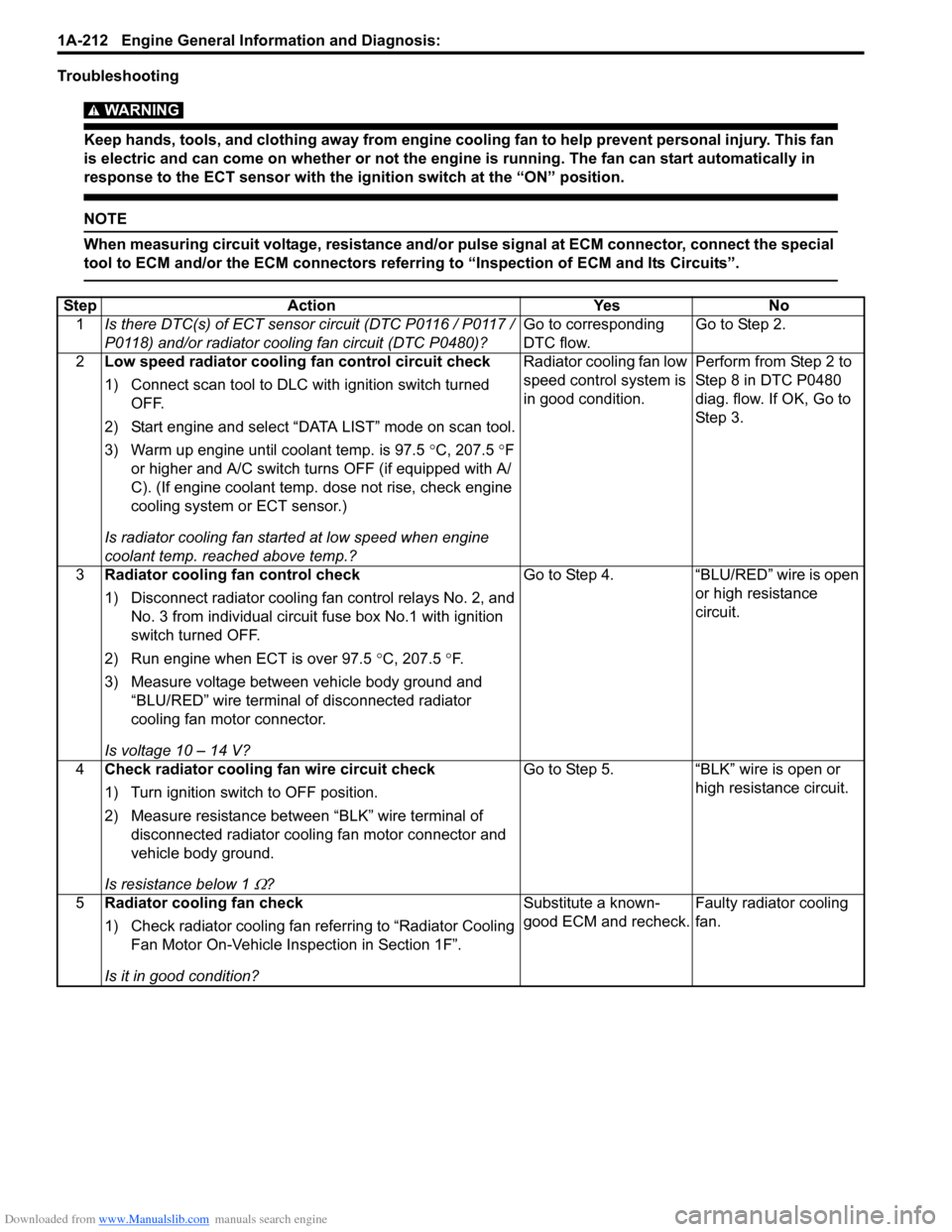
Troubleshooting
WARNING!
Keep hands, tools, and clothing away from engine cooling fan to help prevent personal injury. This fan
is electric and can come on whether or not the engi ne is running. The fan can start automatically in
response to the ECT sensor with the ig nition switch at the “ON” position.
NOTE
When measuring circuit voltage, resistance and/or pulse signal at ECM connector, connect the special
tool to ECM and/or the ECM connectors referri ng to “Inspection of ECM and Its Circuits”.
StepAction YesNo
1 Is there DTC(s) of ECT sensor circuit (DTC P0116 / P0117 /
P0118) and/or radiator cooling fan circuit (DTC P0480)? Go to corresponding
DTC flow.Go to Step 2.
2 Low speed radiator cooling fan control circuit check
1) Connect scan tool to DLC with ignition switch turned
OFF.
2) Start engine and select “DATA LIST” mode on scan tool.
3) Warm up engine until coolant temp. is 97.5 °C, 207.5 °F
or higher and A/C switch turns OFF (if equipped with A/
C). (If engine coolant temp. dose not rise, check engine
cooling system or ECT sensor.)
Is radiator cooling fan started at low speed when engine
coolant temp. reached above temp.? Radiator cooling fan low
speed control system is
in good condition.
Perform from Step 2 to
Step 8 in DTC P0480
diag. flow. If OK, Go to
Ste p 3.
3 Radiator cooling fan control check
1) Disconnect radiator cooling fan control relays No. 2, and
No. 3 from individual circuit fuse box No.1 with ignition
switch turned OFF.
2) Run engine when ECT is over 97.5 °C, 207.5 °F.
3) Measure voltage between vehicle body ground and “BLU/RED” wire terminal of disconnected radiator
cooling fan motor connector.
Is voltage 10 – 14 V? Go to Step 4.
“BLU/RED” wire is open
or high resistance
circuit.
4 Check radiator cooling fan wire circuit check
1) Turn ignition switch to OFF position.
2) Measure resistance between “BLK” wire terminal of
disconnected radiator coolin g fan motor connector and
vehicle body ground.
Is resistance below 1
Ω? Go to Step 5. “BLK” wire is open or
high resistance circuit.
5 Radiator cooling fan check
1) Check radiator cooling fan referring to “Radiator Cooling
Fan Motor On-Vehicle Inspection in Section 1F”.
Is it in good condition? Substitute a known-
good ECM and recheck.
Faulty radiator cooling
fan.
Page 557 of 1496
Downloaded from www.Manualslib.com manuals search engine ABS: 4E-18
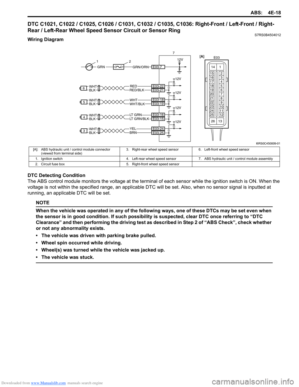
DTC C1021, C1022 / C1025, C1026 / C1031, C1032 / C1035, C1036: Right-Front / Left-Front / Right-
Rear / Left-Rear Wheel Speed Sensor Circuit or Sensor Ring
S7RS0B4504012
Wiring Diagram
DTC Detecting Condition
The ABS control module monitors the voltage at the terminal of each sensor while the ignition swit ch is ON. When the
voltage is not within the specified range, an applicable DTC will be set. Also, when no sensor signal is inputted at
running, an applicable DTC will be set.
NOTE
When the vehicle was operated in any of the following ways, one of these DTCs may be set even when
the sensor is in good condition. If such possibility is suspected, clear DTC once referring to “DTC
Clearance” and then performing the driving test as described in Step 2 of “ABS Check”, check whether
or not any abnormality exists.
• The vehicle was driven with parking brake pulled.
• Wheel spin occurred while driving.
• Wheel(s) was turned while the vehicle was jacked up.
• The vehicle was stuck.
YELBRN
3E03-24
LT GRN/BLKLT GRN
4
WHTWHT/BLK
5
RED
WHTBLK
WHTBLK
WHTBLK
WHTBLKRED/BLK
6
E03-25
E03-15E03-16
E03-19E03-18
E03-22E03-21
12V
12V
12V
12V
12V
7
GRN/ORNE03-7GRN
1
2
[A]
E03
15
16
17
18
19
20
21
22
23
24
25 2
3
4
5
6
7
8
9
10
11
12
1
13
14
26
I6RS0C450009-01
[A]: ABS hydraulic unit / control module connector
(viewed from terminal side) 3. Right-rear wheel speed sensor 6. Left-front wheel speed sensor
1. Ignition switch 4. Left-rear wheel speed sensor 7. ABS hydraulic unit / control module assembly
2. Circuit fuse box 5. Right-front wheel speed sensor
Page 559 of 1496
Downloaded from www.Manualslib.com manuals search engine ABS: 4E-20
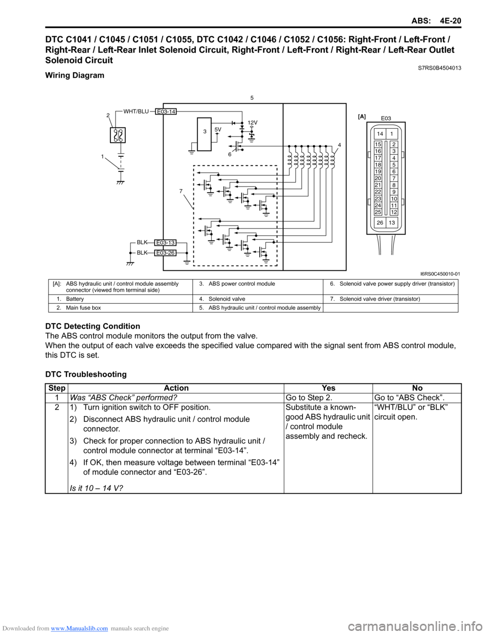
DTC C1041 / C1045 / C1051 / C1055, DTC C1042 / C1046 / C1052 / C1056: Right-Front / Left-Front /
Right-Rear / Left-Rear Inlet Solenoid Circuit, Right-Front / Left-Front / Right-Rear / Left-Rear Outlet
Solenoid Circuit
S7RS0B4504013
Wiring Diagram
DTC Detecting Condition
The ABS control module monitors the output from the valve.
When the output of each valve exceeds the specified value compared with the signal sent from ABS control module,
this DTC is set.
DTC Troubleshooting
6 4
E03-14
5V12V
7
3
WHT/BLU
1 2
5
BLK
BLK
E03-13
E03-26
[A]
E03
15
16
17
18
19
20
21
22
23
24
25 2
3
4
5
6
7
8
9
10
11
12
1
13
14
26
I6RS0C450010-01
[A]: ABS hydraulic unit / control module assembly
connector (viewed from terminal side) 3. ABS power control module 6. Solenoid valve power supply driver (transistor)
1. Battery 4. Solenoid valve 7. Solenoid valve driver (transistor)
2. Main fuse box 5. ABS hydraulic unit / control module assembly
Step Action YesNo
1 Was “ABS Check” performed? Go to Step 2.Go to “ABS Check”.
2 1) Turn ignition switch to OFF position.
2) Disconnect ABS hydraulic unit / control module connector.
3) Check for proper connection to ABS hydraulic unit / control module connector at terminal “E03-14”.
4) If OK, then measure voltage between terminal “E03-14” of module connector and “E03-26”.
Is it 10 – 14 V? Substitute a known-
good ABS hydraulic unit
/ control module
assembly and recheck.
“WHT/BLU” or “BLK”
circuit open.
Page 899 of 1496
Downloaded from www.Manualslib.com manuals search engine Power Assisted Steering System: 6C-17
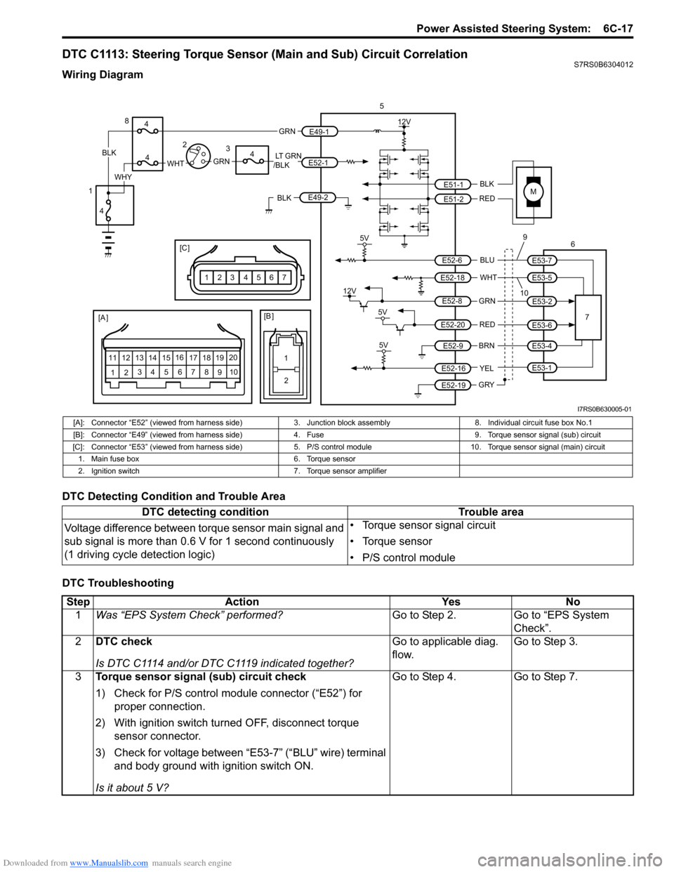
DTC C1113: Steering Torque Sensor (Main and Sub) Circuit CorrelationS7RS0B6304012
Wiring Diagram
DTC Detecting Condition and Trouble Area
DTC Troubleshooting
M
5V
BLK
RED
WHT BLU
GRN
BRN YEL
E51-1
E51-2
E52-18
E53-5
E53-7
E52-6
E52-8
E53-2
E52-9
E52-16
E52-19
GRY
[A ]
12 3
4 5 67
89
11
10
12 13
141516
17 18 19 20
5
67
12V
5V
5V
12V
REDE52-20E53-6
E53-4
E53-1
109
1
2
[B ]
[C ]
7654321
LT GRN
/BLKE52-1 E49-1
GRNGRNWHTBLK
WHY
8
3
4
4
4
4
1 2
E49-2BLK
I7RS0B630005-01
[A]: Connector “E52” (viewed from harness side)
3. Junction block assembly 8. Individual circuit fuse box No.1
[B]: Connector “E49” (viewed from harness side )4. Fuse 9. Torque sensor signal (sub) circuit
[C]: Connector “E53” (viewed from harness side) 5. P/S control module 10. Torque sensor signal (main) circuit
1. Main fuse box 6. Torque sensor
2. Ignition switch 7. Torque sensor amplifier
DTC detecting condition Trouble area
Voltage difference between torque sensor main signal and
sub signal is more than 0.6 V for 1 second continuously
(1 driving cycle detection logic) • Torque sensor signal circuit
• Torque sensor
• P/S control module
Step
Action YesNo
1 Was “EPS System Check” performed? Go to Step 2.Go to “EPS System
Check”.
2 DTC check
Is DTC C1114 and/or DTC C1119 indicated together? Go to applicable diag.
flow.
Go to Step 3.
3 Torque sensor signal (sub) circuit check
1) Check for P/S control module connector (“E52”) for
proper connection.
2) With ignition switch turned OFF, disconnect torque sensor connector.
3) Check for voltage between “E53-7” (“BLU” wire) terminal and body ground with ignition switch ON.
Is it about 5 V? Go to Step 4.
Go to Step 7.
Page 903 of 1496
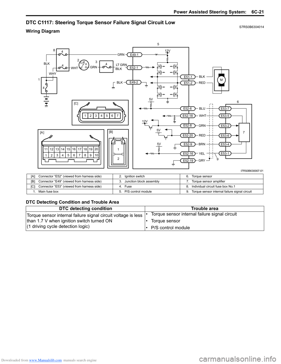
Downloaded from www.Manualslib.com manuals search engine Power Assisted Steering System: 6C-21
DTC C1117: Steering Torque Sensor Failure Signal Circuit LowS7RS0B6304014
Wiring Diagram
DTC Detecting Condition and Trouble Area
M
5V
BLK
RED
WHT BLU
GRN
BRN YEL
E51-1
E51-2
E52-18
E53-5
E53-7
E52-6
E52-8
E53-2
E52-9
E52-16
E52-19
GRY
[A ]
12 3
4 5 67
89
11
10
12 13
141516
17 18 19 20
5
67
12V
5V
5V
12V
REDE52-20E53-6
E53-4
E53-1
9
12
[B]
[C ]
7654321
LT GRN
/BLKE52-1 E49-1
GRNGRNWHTBLK
WHY
8
3
4
4
4
4
1 2
E49-2BLK
I7RS0B630007-01
[A]: Connector “E52” (viewed from harness side)
2. Ignition switch6. Torque sensor
[B]: Connector “E49” (viewed from harness side) 3. Junction block assembly7. Torque sensor amplifier
[C]: Connector “E53” (viewed from harness side) 4. Fuse8. Individual circuit fuse box No.1
1. Main fuse box 5. P/S control module9. Torque sensor internal failure signal circuit
DTC detecting condition Trouble area
Torque sensor internal failure signal circuit voltage is less
than 1.7 V when ignition switch turned ON
(1 driving cycle detection logic) • Torque sensor internal failure signal circuit
• Torque sensor
• P/S control module
Page 916 of 1496
![SUZUKI SWIFT 2006 2.G Service Workshop Manual Downloaded from www.Manualslib.com manuals search engine 6C-34 Power Assisted Steering System:
P/S Control Module Power Supply and Ground Circuit CheckS7RS0B6304022
Wiring Diagram
1
[A ]
123
4 5 67
8 SUZUKI SWIFT 2006 2.G Service Workshop Manual Downloaded from www.Manualslib.com manuals search engine 6C-34 Power Assisted Steering System:
P/S Control Module Power Supply and Ground Circuit CheckS7RS0B6304022
Wiring Diagram
1
[A ]
123
4 5 67
8](/manual-img/20/7607/w960_7607-915.png)
Downloaded from www.Manualslib.com manuals search engine 6C-34 Power Assisted Steering System:
P/S Control Module Power Supply and Ground Circuit CheckS7RS0B6304022
Wiring Diagram
1
[A ]
123
4 5 67
89
11
10
12 13
141516
17 18 19 20
[B ]
7
1
2
MBLK
REDE51-1
E51-2
12V
LT GRN
/BLKE52-1 E49-1
GRNGRNWHTBLK
WHY
3
3
5
6
1 2
E49-2BLK
I7RS0B630012-01
[A]: Connector “E52” (viewed from harness side)
2. Ignition switch5. “EPS” fuse
[B]: Connector “E49” (viewed from harness side) 3. Individual circuit fuse box No.1 6. “IG1 SIG” fuse
1. Main fuse box 4. Junction block assembly7. P/S control module
StepAction YesNo
1 Circuit fuse check
1) Disconnect P/S control modu le connector with ignition
switch turned OFF.
2) Check for proper connection to P/S control module connector at “E49-1”, “E49-2” and “E52-1” terminals.
3) If OK, check “P/S” fuse and “IG1 SIG” fuse for blowing.
Are “P/S” fuse and “IG1 SIG” fuse in good condition? Go to Step 2.
Replace fuse(s) and
check for short in
circuits connected to
fuse(s).
2 Power supply circuit check
1) Measure voltage between “E49-1” terminal of P/S
control module connector and body ground.
Is voltage 10 - 14 V? Go to Step 3.
“GRN” or “BLK” wire is
open circuit.
3 Ignition signal check
1) Turn ignition switch to ON position.
2) Measure voltage between “E52-1” terminal of P/S
control module connector and body ground.
Is voltage 10 - 14 V? Go to Step 4.
“LT GRN/BLK” or “GRN”
wire is open circuit.
4 P/S control module ground circuit check
1) Turn ignition switch to OFF position.
2) Disconnect connectors from P/S control module.
3) Measure resistance between “E49-2” terminals of P/S
control module connector and body ground.
Is resistance 1
Ω or less? Go to Step 5. “BLK” wire is open or
high resistance circuit.
Page 997 of 1496
Downloaded from www.Manualslib.com manuals search engine Air Conditioning System: Automatic Type 7B-49
Step 7. Final confirmation test
Confirm if the problem symptom is troubleshoot and the A/C system is free from any abnormal conditions. If there
existed DTC, clear the DTC. Then , check if the DTC is still detected and if there is any other DTC.
Visual InspectionS7RS0B7224009
Check visually the following parts and systems.
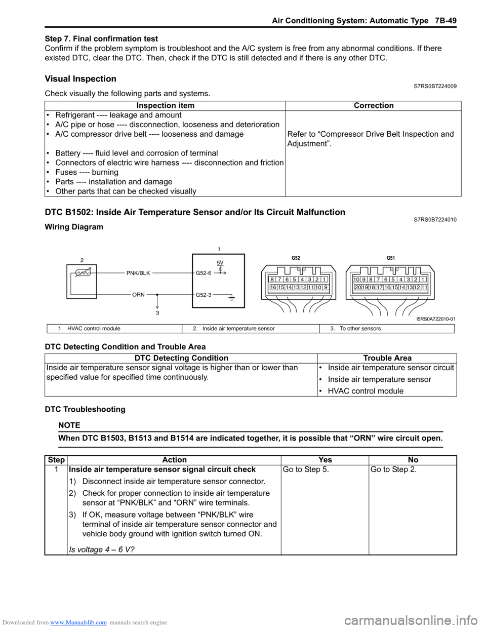
DTC B1502: Inside Air Temperature Sensor and/or Its Circuit MalfunctionS7RS0B7224010
Wiring Diagram
DTC Detecting Condition and Trouble Area
DTC Troubleshooting
NOTE
When DTC B1503, B1513 and B1514 are indicated together, it is possible that “ORN” wire circuit open.
Inspection item Correction
• Refrigerant ---- leakage and amount
• A/C pipe or hose ---- disconnection, looseness and deterioration
• A/C compressor drive belt ---- looseness and damage Refer to “Compressor Drive Belt Inspection and
Adjustment”.
• Battery ---- fluid level and corrosion of terminal
• Connectors of electric wire harn ess ---- disconnection and friction
• Fuses ---- burning
• Parts ---- installation and damage
• Other parts that can be checked visually
5V
PNK/BLK
ORN G52-6
G52-3
2
1
3
7812910
65 431516 14 13 12 11
G52
789101920121112
65 431718 16 15 14 13
G51
I5RS0A722010-01
1. HVAC control module
2. Inside air temperature sensor 3. To other sensors
DTC Detecting Condition Trouble Area
Inside air temperature sensor signal voltage is higher than or lower than
specified value for specified time continuously. • Inside air temperature sensor circuit
• Inside air temperature sensor
• HVAC control module
Step
Action YesNo
1 Inside air temperature sensor signal circuit check
1) Disconnect inside air temperature sensor connector.
2) Check for proper connection to inside air temperature
sensor at “PNK/BLK” and “ORN” wire terminals.
3) If OK, measure voltage between “PNK/BLK” wire terminal of inside air temp erature sensor connector and
vehicle body ground with ignition switch turned ON.
Is voltage 4 – 6 V? Go to Step 5.
Go to Step 2.
Page 1114 of 1496
Downloaded from www.Manualslib.com manuals search engine 8B-76 Air Bag System:
NOTE
Upon completion of inspection and repair work, perform the following items.
• Reconnect all air bag system components, ensure all components are properly mounted.
• Clear DTCs referring to “DTC Clearance”, if any.
• Repeat “Air Bag Diagnostic System Check” to confirm that the trouble has been corrected.
DTC B1071: Forward-Sensor Performance ProblemS7RS0B8204034
DTC Will Set when
SDM receives internal fault signal or wrong ID (Part No.) signal from forward-sensor.
DTC Troubleshooting1) Turn ignition switch OFF.
2) Replace forward-sensor referring to “Forward-Sensor Removal and Installation”.
3) Repeat “Air Bag Diagnostic System Check”.
DTC B1072: Forward-Sensor Communication ErrorS7RS0B8204035
DTC Will Set when
Forward-sensor abnormal signal is detected by SDM.
DTC Troubleshooting
1) Turn ignition switch OFF.
2) Replace forward-sensor referring to “Forward-Sensor Removal and Installation”.
3) Repeat “Air Bag Diagnostic System Check”.
NOTE
Upon completion of inspection and repair work, perform the following items.
• Reconnect all air bag system components and ensure all components are properly mounted.
• Clear DTCs referring to “DTC Clearance”, if any.
• Repeat “Air Bag Diagnostic System Check” to confirm that the trouble has been corrected.
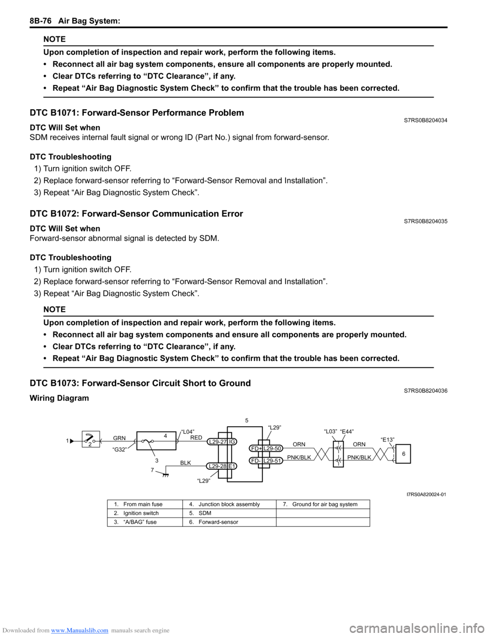
DTC B1073: Forward-Sensor Circuit Short to GroundS7RS0B8204036
Wiring Diagram
1 2
3
GRN
RED
7
BLK
L29-27
L29-28 IG
E1
4
“L29”
“L04”
“G32”
“L29”5
ORN
PNK/BLK
ORN
PNK/BLKL29-50
FD+
L29-51
FD-6
“E13”
“L03”“E44”
I7RS0A820024-01
1. From main fuse 4. Junction block assembly 7. Ground for air bag system
2. Ignition switch 5. SDM
3. “A/BAG” fuse 6. Forward-sensor