2006 SUZUKI SWIFT torque control arm
[x] Cancel search: torque control armPage 675 of 1496

Downloaded from www.Manualslib.com manuals search engine Automatic Transmission/Transaxle: 5A-31
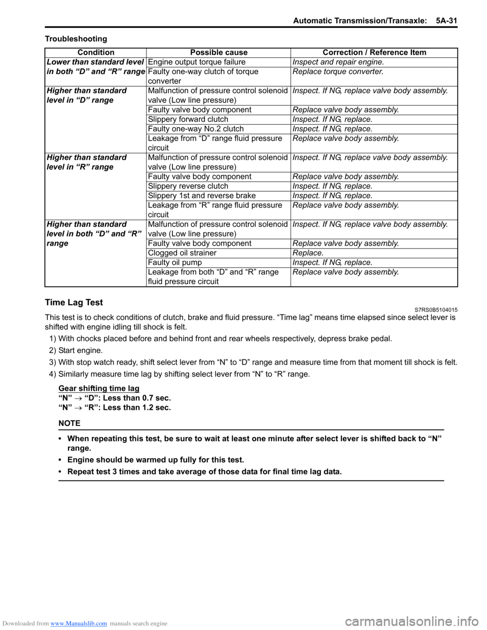
Troubleshooting
Time Lag TestS7RS0B5104015
This test is to check conditions of clutch, brake and fluid pressure. “Time lag” means time elapsed since select lever is
shifted with engine idling till shock is felt.
1) With chocks placed before and behind front and rear wheels respectively, depress brake pedal.
2) Start engine.
3) With stop watch ready, shift select lever from “N” to “D” range an d measure time from that moment till shock is felt.
4) Similarly measure time lag by shifting select lever from “N” to “R” range.
Gear shifting time lag
“N” → “D”: Less than 0.7 sec.
“N” → “R”: Less than 1.2 sec.
NOTE
• When repeating this test, be sure to wait at least one minute after select lever is shifted back to “N”
range.
• Engine should be warmed up fully for this test.
• Repeat test 3 times and take average of those data for final time lag data.
Condition Possible cause Correction / Reference Item
Lower than standard level
in both “D” and “R” range Engine output torque failure
Inspect and repair engine.
Faulty one-way clutch of torque
converter Replace torque converter.
Higher than standard
level in “D” range Malfunction of pressure control solenoid
valve (Low line pressure) Inspect. If NG, replace valve body assembly.
Faulty valve body component Replace valve body assembly.
Slippery forward clutch Inspect. If NG, replace.
Faulty one-way No.2 clutch Inspect. If NG, replace.
Leakage from “D” range fluid pressure
circuit Replace valve body assembly.
Higher than standard
level in “R” range Malfunction of pressure control solenoid
valve (Low line pressure) Inspect. If NG, replace valve body assembly.
Faulty valve body component Replace valve body assembly.
Slippery reverse clutch Inspect. If NG, replace.
Slippery 1st and reverse brake Inspect. If NG, replace.
Leakage from “R” range fluid pressure
circuit Replace valve body assembly.
Higher than standard
level in both “D” and “R”
range Malfunction of pressure control solenoid
valve (Low line pressure)
Inspect. If NG, replace valve body assembly.
Faulty valve body component Replace valve body assembly.
Clogged oil strainer Replace.
Faulty oil pump Inspect. If NG, replace.
Leakage from both “D” and “R” range
fluid pressure circuit Replace valve body assembly.
Page 719 of 1496

Downloaded from www.Manualslib.com manuals search engine Automatic Transmission/Transaxle: 5A-75
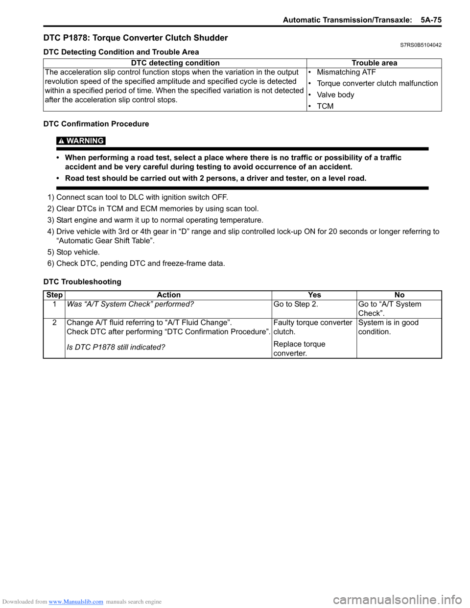
DTC P1878: Torque Converter Clutch ShudderS7RS0B5104042
DTC Detecting Condition and Trouble Area
DTC Confirmation Procedure
WARNING!
• When performing a road test, select a place where there is no traffic or possibility of a traffic accident and be very careful during testing to avoid occurrence of an accident.
• Road test should be carried out with 2 persons, a driver and tester, on a level road.
1) Connect scan tool to DLC with ignition switch OFF.
2) Clear DTCs in TCM and ECM memories by using scan tool.
3) Start engine and warm it up to normal operating temperature.
4) Drive vehicle with 3rd or 4th gear in “D” range and slip c ontrolled lock-up ON for 20 seconds or longer referring to
“Automatic Gear Shift Table”.
5) Stop vehicle.
6) Check DTC, pending DTC and freeze-frame data.
DTC Troubleshooting DTC detecting condition
Trouble area
The acceleration slip control function stops when the variation in the output
revolution speed of the specified amp litude and specified cycle is detected
within a specified period of time. When t he specified variation is not detected
after the acceleration slip control stops. • Mismatching ATF
• Torque converter clutch malfunction
• Valve body
•TCM
Step
Action YesNo
1 Was “A/T System Check” performed? Go to Step 2.Go to “A/T System
Check”.
2 Change A/T fluid referring to “A/T Fluid Change”. Check DTC after performing “DTC Confirmation Procedure”.
Is DTC P1878 still indicated? Faulty torque converter
clutch.
Replace torque
converter.System is in good
condition.
Page 727 of 1496

Downloaded from www.Manualslib.com manuals search engine Automatic Transmission/Transaxle: 5A-83
Connector “C34”Terminal Wire color Circuit Standard
voltage Condition
1 BLK Ground 0 – 1 V Ignition switch ON
2 LT GRN/
BLK Pressure control
solenoid valve (–)
0.6 – 1.0 V Ignition switch ON
3WHT/BLK TCC pressure control
solenoid valve (–) 0.6 – 1.0 V Ignition switch ON
4GRY Pressure control
solenoid valve (+) *0 – 0.6 V
↑↓
10 – 14 V
(“Reference waveform No. 1: ”) Engine running at idling.
(Output signal is duty pulse. Duty ratio varies
depending on throttle valve opening.)
5WHT/BLU TCC pressure control
solenoid valve (+) *0 – 0.6 V
↑↓
10 – 14 V
(“Reference waveform No. 2: ”) Engine running at idling.
(Output signal is duty pulse. Duty ratio varies
depending on torque converter clutch operating
condition.)
6 YEL/BLK Power source 10 – 14 V Ignition switch ON
7WHT CAN communication
line (Low) *2.5 – 3.6 V
↑↓
1.6 – 2.5 V
(“Reference waveform No. 3: ”) Engine running at idling with after warming up.
(CAN communication signal is pulse. Pulse signal
frequency varies depending on engine condition.))
8— — — —
9— — — —
10 — —— —
11 LT G R N Transmission fluid
temperature sensor (+) 2.9 – 3.1 V Ignition switch ON, fluid temperature is 20
°C (68 °F)
0.3 – 0.5 V Ignition switch ON, fluid temperature is 100 °C (212 °F)
12 ORN Transmission fluid
temperature sensor (–) 0 – 1 V Ignition switch ON
13 — —— —
14 BLU/BLK Timing solenoid valv e 0 – 1 V Ignition switch ON
15 BLK/YEL Shift solenoid valve-B
(No.2) 9 – 14 V Ignition switch ON, select lever in “P” range
16 BRN Shift solenoid valve-A
(No.1) 9 – 14 V Ignition switch ON, select lever in “P” range
17 RED CAN communication
line (High) *2.5 – 3.6 V
↑↓
1.6 – 2.5 V
(“Reference waveform No. 3: ”) Engine running at idling with after warming up.
(CAN communication signal is pulse. Pulse signal
frequency varies depending on engine condition.)
18 — —— —
19 — —— —
20 — —— —
21 — —— —
22 — —— —
23 BLK Ground 0 – 1 V Ignition switch ON
24 WHT/RED Power source
for back-
up 10 – 14 V Constantly
Page 745 of 1496

Downloaded from www.Manualslib.com manuals search engine Automatic Transmission/Transaxle: 5A-101
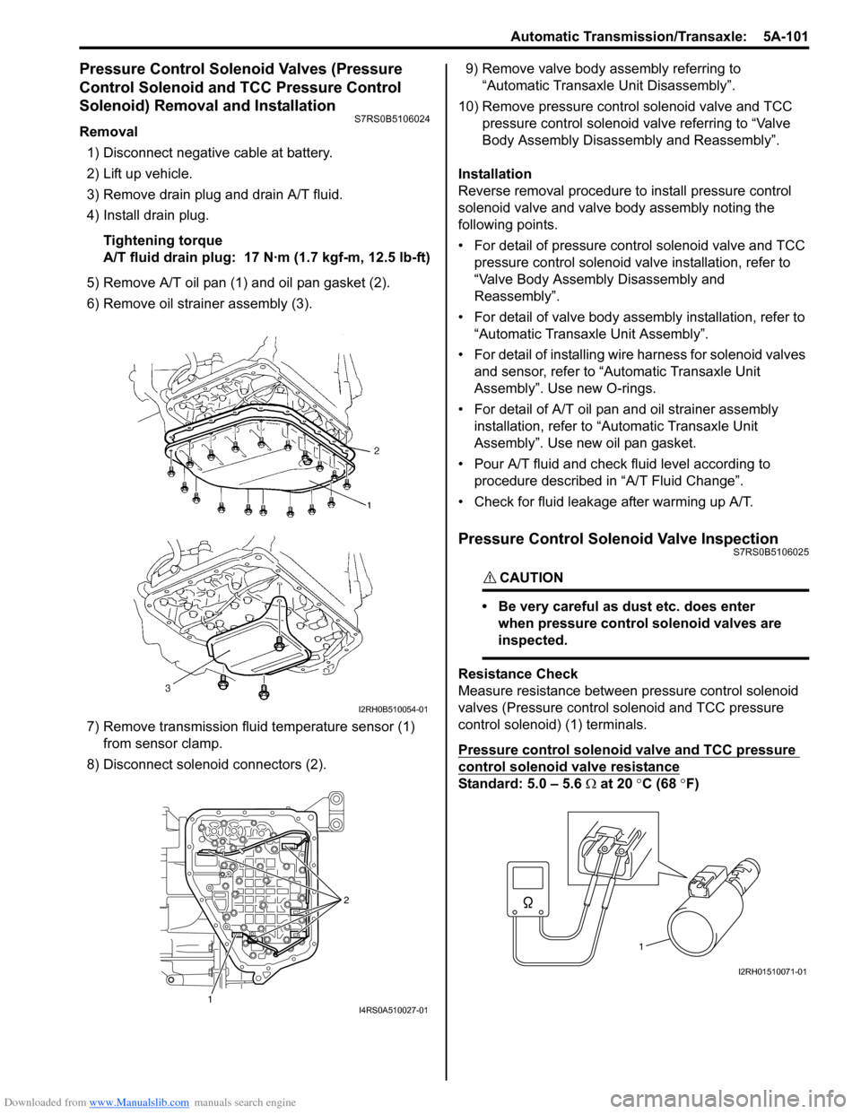
Pressure Control Solenoid Valves (Pressure
Control Solenoid and TCC Pressure Control
Solenoid) Removal and Installation
S7RS0B5106024
Removal1) Disconnect negative cable at battery.
2) Lift up vehicle.
3) Remove drain plug and drain A/T fluid.
4) Install drain plug.
Tightening torque
A/T fluid drain plug: 17 N·m (1.7 kgf-m, 12.5 lb-ft)
5) Remove A/T oil pan (1) and oil pan gasket (2).
6) Remove oil strain er assembly (3).
7) Remove transmission fluid temperature sensor (1) from sensor clamp.
8) Disconnect solenoid connectors (2). 9) Remove valve body assembly referring to
“Automatic Transaxl e Unit Disassembly”.
10) Remove pressure control solenoid valve and TCC pressure control solenoid valve referring to “Valve
Body Assembly Disassembly and Reassembly”.
Installation
Reverse removal procedure to install pressure control
solenoid valve and valve body assembly noting the
following points.
• For detail of pressure control solenoid valve and TCC pressure control solenoid va lve installation, refer to
“Valve Body Assembly Disassembly and
Reassembly”.
• For detail of valve body asse mbly installation, refer to
“Automatic Transaxle Unit Assembly”.
• For detail of installing wire harness for solenoid valves and sensor, refer to “Automatic Transaxle Unit
Assembly”. Use new O-rings.
• For detail of A/T oil pan and oil strainer assembly
installation, refer to “A utomatic Transaxle Unit
Assembly”. Use new oil pan gasket.
• Pour A/T fluid and check fluid level according to procedure described in “A/T Fluid Change”.
• Check for fluid leakage after warming up A/T.
Pressure Control Solenoid Valve InspectionS7RS0B5106025
CAUTION!
• Be very careful as dust etc. does enter when pressure control solenoid valves are
inspected.
Resistance Check
Measure resistance between pressure control solenoid
valves (Pressure control solenoid and TCC pressure
control solenoid) (1) terminals.
Pressure control solenoid valve and TCC pressure
control solenoid valve resistance
Standard: 5.0 – 5.6 Ω at 20 °C (68 °F)
I2RH0B510054-01
1 2I4RS0A510027-01
1
I2RH01510071-01
Page 817 of 1496

Downloaded from www.Manualslib.com manuals search engine Manual Transmission/Transaxle: 5B-3
Diagnostic Information and Procedures
Manual Transaxle Symptom DiagnosisS7RS0B5204001
Repair Instructions
Manual Transaxle Oil ChangeS7RS0B5206001
1) Before changing or inspecting oil, be sure to stop engine and lift vehicle horizontally.
2) With vehicle lifted up, check oil level and leakage. If leakage exists, correct it.
NOTE
Whenever vehicle is hoisted for any other
service work than oil change, also be sure to
check for oil leakage.
3) Remove oil filler plug (2).
4) Remove drain plug (1), and drain old oil. 5) Apply sealant to thread of drain plug (1), and tighten
it to specified torque.
“A”: Sealant 99000–31260 (SUZUKI Bond
No.1217G)
Tightening torque
Transaxle oil drain plug (a): 21 N·m (2.1 kgf-m,
15.5 lb-ft)
6) Pour new specified oil unt il oil level reaches bottom
of oil filler plug hole (3) as shown in figure.NOTE
It is highly recommended to use API GL-4
75W-90 gear oil.
Transaxle oil specification
: API GL-4 (For SAE classification, refer to
viscosity chart [A] in figure.)
Manual transaxle oil capacity
Reference: 2.0 liters (4.2/3.5 US/Imp. pt)
Condition Possible cause Correction / Reference Item
Gears slipping out of
mesh Worn shift fork shaft
Replace.
Worn shift fork or synchronizer sleeve Replace.
Weak or damaged locating springs Replace.
Worn bearings on input shaft or
countershaft Replace.
Worn chamfered tooth on sleeve and
gear Replace sleeve and gear.
Hard shifting Maladjusted gear select control cable Adjust.
Inadequate or insufficient lubricant Replenish.
Improper clutch pedal free travel Replace clutch master cylinder or clutch pedal
arm.
Distorted or broken clutch disc Replace.
Damaged clutch pressure plate Replace clutch cover.
Worn synchronizer ring Replace.
Worn chamfered tooth on sleeve or gear Replace sleeve or gear.
Worn gear shift / select control cables
joint Replace.
Distorted shift shaft Replace.
Worn gear shift / select control cables Replace.
Noise Inadequate or insufficient lubricant Replenish.
Damaged or worn bearing(s) Replace.
Damaged or worn gear(s) Replace.
Damaged or worn synchronizer parts Replace.
Page 871 of 1496

Downloaded from www.Manualslib.com manuals search engine Steering General Diagnosis: 6A-2
Diagnostic Information and Procedures
Steering Symptom DiagnosisS7RS0B6104001
ConditionPossible cause Correction / Reference Item
Hard steering Tire not adequately inflated Inflate tires to proper pressure.
Malfunction of power steering system Check and correct.
Bind in tie-rod end ball studs or lower
ball joints Replace tie-rod end or front suspension arm.
Disturbed front wheel alignment Check and adjust front wheel alignment.
Bind in steering column Repair or replace steering column.
Rack and pinion adjustment Check and adjustment rack and pinion torque.
Too much play in steering Wheel bearings worn Replace wheel bearing.
Loose steering gear case bolts Tighten gear case bolts.
Faulty steering gear case assembly Replace steering gear case assembly.
Worn steering shaft joints Replace joint.
Worn tie-rod ends or tie-rod inside ball
joints Replace tie-rod end or tie-rod.
Worn lower ball joints Replace front suspension control arm.
Rack and pinion adjustment Check and adjustment rack and pinion torque.
Poor return ability Bind in tie-rod end ball studs Replace tie-rod end.
Bind in ball joints Replace front suspension control arm.
Bind in steering column Repair or replace steering column.
Disturbed front end alignment Check and adjust front end alignment.
Faulty steering gear case assembly Replace steering gear case assembly.
Tires not adequately inflated Adjust tire pressure.
Rack and pinion adjustment Check and adjustment rack and pinion torque.
Rack and pinion noise
(Rattle or chuckle) Loose steering gear case bolts
Tighten steering gear case bolts.
Rack and pinion adjustment Check and adjustment rack and pinion torque.
Faulty steering gear case assembly Replace steering gear case assembly.
Broken or other wise damaged wheel
bearing(s) Replace wheel bearing(s).
Wander or poor steering
stability Mismatched or uneven tires
Replace or inflate tires to proper pressure.
Loosen ball joints and tie-rod ends Replace suspension control arm or tie-rod end.
Faulty struts or mountings Replace strut or repair mounting.
Loose stabilizer bar Tighten or replace stabilizer bar or bush.
Broken or sagging springs Replace spring.
Rack and pinion adjustment Check and adjustment rack and pinion torque.
Disturbed front wheel alignment Check and adjust front wheel alignment.
Faulty steering gear case assembly Replace steering gear case assembly.
Erratic steering when
braking Worn wheel bearing(s)
Replace wheel bearing(s).
Broken or sagging spring(s) Replace coil spring(s).
Wheel tires are inflated unequally Inflate tires to proper pressure.
Disturbed front wheel alignment Check and adjust front wheel alignment.
Brakes not working in unison Check and repair brake system.
Leaking caliper Repair or replace caliper.
Warped discs Replace brake disc.
Badly worn brake pads Replace brake pads.
Page 893 of 1496

Downloaded from www.Manualslib.com manuals search engine Power Assisted Steering System: 6C-11
Scan Tool DataS7RS0B6304006
NOTE
When P/S motor is cold condition (that is, armature coil of P/S motor is not heated), normal value with
asterisk (*) mark in the following table is displayed on scan tool.
�) C1143 P/S motor circuit current too
high Measured motor drive current is
more than 50 A.
• P/S motor circuit
• P/S motor
• P/S control module1 driving
cycle
�) C1145 P/S motor circuit current too
low Measured motor drive current is
less than 2 A continuously for
more than 3 seconds even though
target motor drive current is more
than 4 A.
or
Measured motor drive current is
less than 0.8 A for total 1 second
even though motor control duty is
more than 90% while target motor
drive current is less than 8 A. 1 driving
cycle
�) C1153 P/S control module power
supply circuit Power supply voltage of P/S
control module is less than 9 V for
5 seconds continuously. • P/S control module power
supply circuit
• Undercharged Battery
• P/S control module 1 driving
cycle
�) C1155 P/S control module internal
failure Internal memory (EEPROM) is
data error.
• P/S control moduleNot
applicable
Internal circuit is faulty.
or
Power supply voltage of P/S
control module exceeded 17.5 V. • Overcharged Battery
• P/S control module
1 driving
cycle
DTC No. Detecting item
Detecting condition
(DTC will set when detecting) Trouble area MIL
Scan tool data
Vehicle conditionNormal condition
�) Battery Voltage
Ignition switch ON 10 – 14 V
�) TQS Power Supply 10 – 14 V
�) TQS Main Torque Engine running at idle speed Steering wheel at fully turned to left –9.4 – 0 N
⋅m
Steering wheel at free 0 N⋅m
Steering wheel at fully turned to right 0 – 9.4 N ⋅m
�) TQS Sub Torque Engine running at idle speed Steering wheel at fully turned to left –9.4 – 0 N
⋅m
Steering wheel at free 0 N⋅m
Steering wheel at fully turned to right 0 – 9.4 N ⋅m
�) Assist Torque Engine running at idle speed Steering wheel at fully turned to left –9.4 – 0 N
⋅m
Steering wheel at free 0 N⋅m
Steering wheel at fully turned to right 0 – 9.4 N ⋅m
�) Motor Control Engine running at idle speed Steering wheel at free
0 A
Steering wheel at fully turned to left or right *35 – 45 A
�) Motor Monitor Engine running at idle speed Steering wheel at free
0 A
Steering wheel at fully turned to left or right *35 – 45 A
�) Vehicle Speed Engine running and vehicle at stop 0 km/h
�) Engine Speed Engine running at idle speed after warming up 700 ± 50 rpm
�) Motor Volt Engine running at idle speed Steering wheel at free
0.8 – 1 V
Steering wheel at fully turned to right About 5 V
�) Ignition switch Ignition switch ON ON