Page 510 of 1496

Downloaded from www.Manualslib.com manuals search engine 4A-12 Brake Control System and Diagnosis:
Master Cylinder Assembly Removal and
Installation
S7RS0B4106011
CAUTION!
Do not allow brake fluid to get on painted
surfaces. Painted surfaces will be damaged
by brake fluid, flush it with water immediately
if any fluid is spilled.
Removal
1) Clean outside of master cylinder.
2) Drain brake fluid in reservoir.
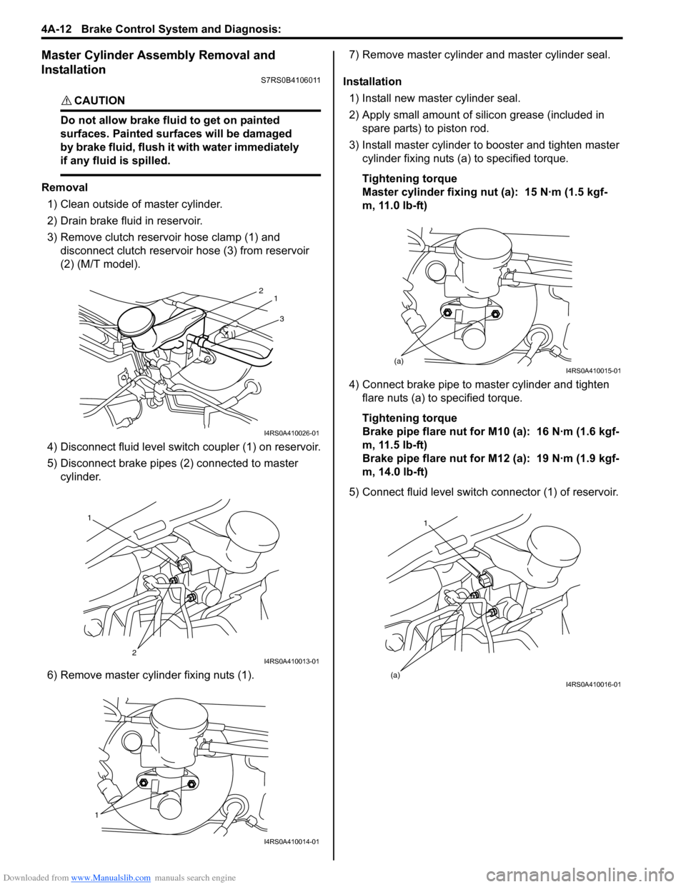
3) Remove clutch reservoir hose clamp (1) and disconnect clutch reservoir hose (3) from reservoir
(2) (M/T model).
4) Disconnect fluid level switch coupler (1) on reservoir.
5) Disconnect brake pipes (2) connected to master cylinder.
6) Remove master cylinder fixing nuts (1). 7) Remove master cylinder and master cylinder seal.
Installation 1) Install new master cylinder seal.
2) Apply small amount of silic on grease (included in
spare parts) to piston rod.
3) Install master cylinder to booster and tighten master cylinder fixing nuts (a) to specified torque.
Tightening torque
Master cylinder fixing nut (a): 15 N·m (1.5 kgf-
m, 11.0 lb-ft)
4) Connect brake pipe to master cylinder and tighten flare nuts (a) to specified torque.
Tightening torque
Brake pipe flare nut for M10 (a): 16 N·m (1.6 kgf-
m, 11.5 lb-ft)
Brake pipe flare nut for M12 (a): 19 N·m (1.9 kgf-
m, 14.0 lb-ft)
5) Connect fluid level switch connector (1) of reservoir.
3
2
1
I4RS0A410026-01
1
2
I4RS0A410013-01
1
I4RS0A410014-01
(a)I4RS0A410015-01
1
(a)
I4RS0A410016-01
Page 631 of 1496

Downloaded from www.Manualslib.com manuals search engine Electronic Stability Program: 4F-57
3) Remove front brake pipe referring to “Front Brake Hose / Pipe Removal and In stallation in Section 4A”.
4) Remove ESP ® hydraulic unit / control module with
bracket from vehicle by removing bracket bolts.
5) Remove bolt (4) and pull out ESP ® hydraulic unit /
control module assembly (1) from bracket (3) using
flat end rod or the like (2).
Installation 1) Install hydraulic unit / co ntrol module assembly and
by reversing removal procedure.
Tightening torque
Brake pipe flare nut: 16 N·m (1.6 kgf-m, 11.5 lb-
ft)
ESP ® hydraulic unit / control module assembly
bolt: 9 N·m (0.9 kgf-m, 6.5 lb-ft)
ESP ® hydraulic unit / control module assembly
bracket bolt: 25 N·m (2.5 kgf-m, 18.0 lb-ft)
2) Bleed air from brake system referring to “Air Bleeding of Brake System in Section 4A”.
3) Check each installed part for fluid leakage.
4) Connect SUZUKI Scan Tool.
5) Turn ignition switch to ON position. And SLIP indicator lamp flush. (Other than replace with new
one) If other than SLIP indicator lamp light, check
DTC and repair it.
6) Turn ignition switch to ON position. And ESP®
warning lamp, SLIP indicator lamp, ESP ® OFF
lamp, Brake warning lamp lights and ABS warning
lamp flush. (Replace new one)
7) Check DTC.
NOTE
If any DTC(s) other than C1075, C1076 or
C1078 are detected, sensor calibration can
not be completed. Repair the detected it(s)
first.
8) Perform “Sensor Calibration”.
9) Perform “ESP ® Hydraulic Unit Operation Check”.
10) Turn ignition switch to OFF position once and then
ON position. In this state, make sure that indicator
light and warning light turns off.
11) Check DTC(s) are not stored in hydraulic unit / control module.
Front / Rear Wheel Speed Sensor On-Vehicle
Inspection
S7RS0B4606028
CAUTION!
Incorrect voltage and/or wrong connection
cause damage to wheel speed sensor.
Output Voltage Inspection
1) Disconnect negative (–) cable from battery.
2) Hoist vehicle a little.
3) Disconnect wheel speed sensor connector.
4) Disconnect wheel speed grommet from vehicle body.
5) Set up measuring devices as shown in figure, the resistance to 115 Ω and the power supply voltage
to12 V.
4
1
2 3
I6RS0B460030-02
[A]: Front wheel speed sensor 3. “WHT” wire terminal
[B]: Rear wheel speed sensor 4. “BLK” wire terminal
1. Wheel speed sensor connector 5. Power supply (12 V)
2. Resistance (115 Ω)
V
2
5
4 1
3
43
1
[A]
[B]
I6RS0B460031-02
Page 824 of 1496

Downloaded from www.Manualslib.com manuals search engine 5B-10 Manual Transmission/Transaxle:
16) Remove engine under covers.
17) Support transaxle with transmission jack.
18) Remove transaxle to engine bolts and nut of lower side.
19) Remove engine left mounting (1) with bracket (2).
20) Remove engine rear mounting bracket bolts (1).
21) Remove other attached parts from transaxle, if any.
22) Pull transaxle so as to disconnect input shaft from clutch disc, and then lower it. Remounting
CAUTION!
• Care should be taken not to scratch oil
seal lip with drive shaft while raising
transaxle.
• Do not hit drive shaft joint with hammer when installing it into differential gear.
Reverse dismounting procedure for remounting noting
the following.
• Tighten each bolts and nuts to specified torque referring to “Manual Transaxle Unit Components”.
• Set each clamp for wiring securely.
• Fill transaxle oil referring to “Manual Transaxle Oil
Change”.
• Fill coolant referring to “Cooling System Flush and
Refill in Section 1F”.
• Install hook (1) and ground cable (2) at specified position as shown in figure.
• Connect battery and check function of engine, clutch
and transaxle.
1
2
I4RS0A520021-01
1
I4RS0A520022-01
3. Transaxle side cover 4. Transaxle left case
90
1
2 3
4
I4RS0A520023-01
Page 1414 of 1496

Downloaded from www.Manualslib.com manuals search engine 10B-11 Body Electrical Control System:
Customer Complaint Analysis
Record details of the problem (failure, complaint) and how it occurred as described by the customer.
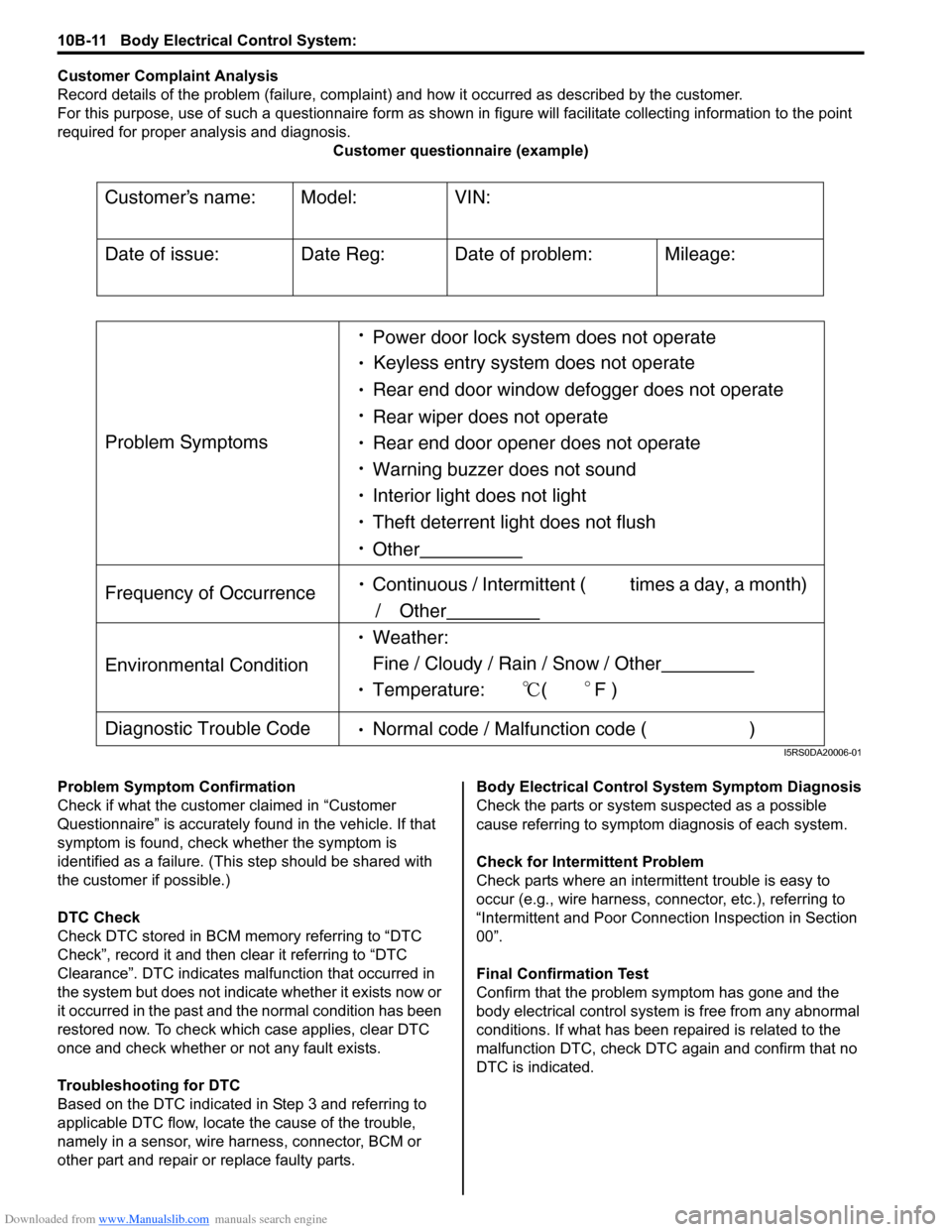
For this purpose, use of such a questionnaire form as shown in figure will facilitate collectin g information to the point
required for proper analysis and diagnosis. Customer questionnaire (example)
Problem Symptom Confirmation
Check if what the custom er claimed in “Customer
Questionnaire” is accurately f ound in the vehicle. If that
symptom is found, check whether the symptom is
identified as a failure. (This step should be shared with
the customer if possible.)
DTC Check
Check DTC stored in BCM me mory referring to “DTC
Check”, record it and then clear it referring to “DTC
Clearance”. DTC indicates malfunction that occurred in
the system but does not indicate whether it exists now or
it occurred in the past and the normal condition has been
restored now. To check which case applies, clear DTC
once and check whether or not any fault exists.
Troubleshooting for DTC
Based on the DTC indicated in Step 3 and referring to
applicable DTC flow, locate the cause of the trouble,
namely in a sensor, wire harness, connector, BCM or
other part and repair or replace faulty parts. Body Electrical Control System Symptom Diagnosis
Check the parts or system
suspected as a possible
cause referring to symptom diagnosis of each system.
Check for Intermi ttent Problem
Check parts where an intermit tent trouble is easy to
occur (e.g., wire harness, connector, etc.), referring to
“Intermittent and Poor Connec tion Inspection in Section
00”.
Final Confirmation Test
Confirm that the problem symptom has gone and the
body electrical control system is free from any abnormal
conditions. If what has been repaired is related to the
malfunction DTC, check DTC again and confirm that no
DTC is indicated.
Customers name:
Model:
VIN:
Date of issue:
Date Reg:
Date of problem:
Mileage:
Problem Symptoms
Power door lock system does not operate
Keyless entry system does not operate
Rear end door window defogger does not operate
Rear wiper does not operate
Rear end door opener does not operate
Other
Frequency of Occurrence
Continuous / Intermittent ( times a day, a month)
/ Other
Environmental Condition
Weather:
Fine / Cloudy / Rain / Snow / Other
Temperature: (F )
Diagnostic Trouble Code Normal code / Malfunction code ( )
Warning buzzer does not sound
Interior light does not light
Theft deterrent light does not flush
I5RS0DA20006-01
Page:
< prev 1-8 9-16 17-24