2006 SUZUKI SWIFT heater motor
[x] Cancel search: heater motorPage 956 of 1496
Downloaded from www.Manualslib.com manuals search engine 7B-8 Air Conditioning System: Manual Type
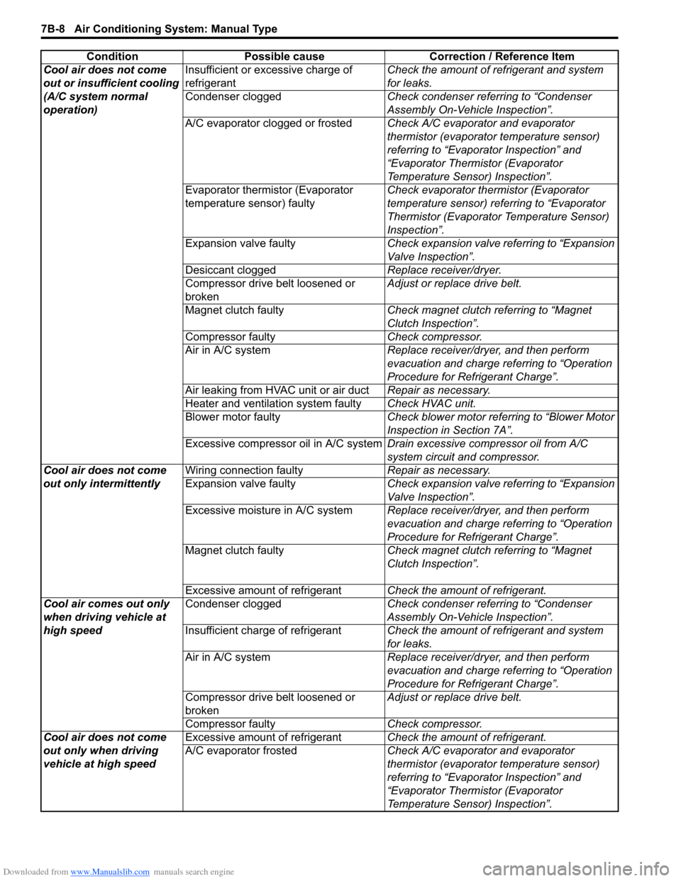
Cool air does not come
out or insufficient cooling
(A/C system normal
operation)Insufficient or excessive charge of
refrigerant
Check the amount of refrigerant and system
for leaks.
Condenser clogged Check condenser referring to “Condenser
Assembly On-Vehicle Inspection”.
A/C evaporator clogged or frosted Check A/C evaporator and evaporator
thermistor (evaporator temperature sensor)
referring to “Evaporator Inspection” and
“Evaporator Thermistor (Evaporator
Temperature Sensor) Inspection”.
Evaporator thermistor (Evaporator
temperature sensor) faulty Check evaporator thermistor (Evaporator
temperature sensor) referring to “Evaporator
Thermistor (Evaporator Temperature Sensor)
Inspection”.
Expansion valve faulty Check expansion valve referring to “Expansion
Valve Inspection”.
Desiccant clogged Replace receiver/dryer.
Compressor drive belt loosened or
broken Adjust or replace drive belt.
Magnet clutch faulty Check magnet clutch referring to “Magnet
Clutch Inspection”.
Compressor faulty Check compressor.
Air in A/C system Replace receiver/dryer, and then perform
evacuation and charge referring to “Operation
Procedure for Refrigerant Charge”.
Air leaking from HVAC unit or air duct Repair as necessary.
Heater and ventilation system faulty Check HVAC unit.
Blower motor faulty Check blower motor referring to “Blower Motor
Inspection in Section 7A”.
Excessive compressor oil in A/C system Drain excessive compressor oil from A/C
system circuit and compressor.
Cool air does not come
out only intermittently Wiring connection faulty
Repair as necessary.
Expansion valve faulty Check expansion valve referring to “Expansion
Valve Inspection”.
Excessive moisture in A/C system Replace receiver/dryer, and then perform
evacuation and charge referring to “Operation
Procedure for Refrigerant Charge”.
Magnet clutch faulty Check magnet clutch referring to “Magnet
Clutch Inspection”.
Excessive amount of refrigerant Check the amount of refrigerant.
Cool air comes out only
when driving vehicle at
high speed Condenser clogged
Check condenser referring to “Condenser
Assembly On-Vehicle Inspection”.
Insufficient charge of refrigerant Check the amount of refrigerant and system
for leaks.
Air in A/C system Replace receiver/dryer, and then perform
evacuation and charge referring to “Operation
Procedure for Refrigerant Charge”.
Compressor drive belt loosened or
broken Adjust or replace drive belt.
Compressor faulty Check compressor.
Cool air does not come
out only when driving
vehicle at high speed Excessive amount of refrigerant
Check the amount of refrigerant.
A/C evaporator frosted Check A/C evaporator and evaporator
thermistor (evaporator temperature sensor)
referring to “Evaporator Inspection” and
“Evaporator Thermistor (Evaporator
Temperature Sensor) Inspection”.
Condition Possible cause Correction / Reference Item
Page 961 of 1496
Downloaded from www.Manualslib.com manuals search engine Air Conditioning System: Manual Type 7B-13
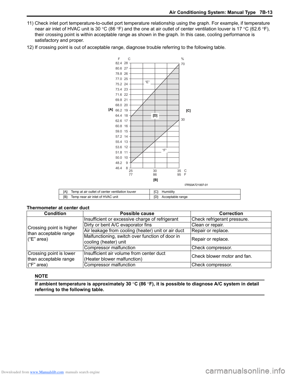
11) Check inlet port temperature-to-outlet port temperature relationship using the graph. For example, if temperature
near air inlet of HVAC unit is 30 °C (86 °F) and the one at air outlet of center ventilation louver is 17 °C (62.6 °F),
their crossing point is within acceptable range as shown in the graph. In this case, cooling performance is
satisfactory and proper.
12) If crossing point is out of acceptable range, diagnose trouble referring to the following table.
Thermometer at center duct
NOTE
If ambient temperature is approximately 30 °C (86 °F), it is possible to diagnose A/C system in detail
referring to the following table.
[A]: Temp at air outlet of center ventilation louver [C]: Humidity
[B]: Temp near air inlet of HVAC unit [D]: Acceptable range
ConditionPossible cause Correction
Crossing point is higher
than acceptable range
(“E” area) Insufficient or excessive charge of refrigerant Check refrigerant pressure.
Dirty or bent A/C evaporator fins
Clean or repair.
Air leakage from cooling (heater) unit or air duct Repair or replace.
Malfunctioning, switch over function of door in
cooling (heater) unit Repair or replace.
Compressor malfunct ion Check compressor.
Crossing point is lower
than acceptable range
(“F” area) Insufficient air volume from center duct
(Heater blower malfunction)
Check blower motor and fan.
Compressor malfunct ion Check compressor.
8 9
10 11 12 13 14
15 16 17 18 19
20
21
22
23
24
25 26
27
28
46.4 48.2 50.0 51.8 53.6 55.4 57.2 59.0 60.8 62.6 64.4
66.2 68.0
69.8
71.6
73.4
75.2
77.0
78.8 80.6
82.4
25 30 35
77 86 95
F C
C
F
“E”
“F”30 70 %
[A]
[B][C]
[D]
I7RS0A721007-01
Page 972 of 1496

Downloaded from www.Manualslib.com manuals search engine 7B-24 Air Conditioning System: Manual Type
HVAC Unit Removal and InstallationS7RS0B7216006
Removal1) Disconnect negative (–) cable from battery.
2) Disable air bag system referring to “Disabling Air Bag System in Section 8B”.
3) Recover refrigerant from A/C system with recovery and recycling equipment referring to “Recovery” in
“Operation Procedure for Refrigerant Charge”.
4) Remove cowl top panel referring to “Cowl Top Components in Section 9K”.
5) Drain engine coolant, and then disconnect heater hoses (1) from HVAC unit (2).
6) Remove instrument panel from vehicle body referring to “Audio Unit Re moval and Installation in
Section 9C”.
7) Loosen suction hose and liquid pipe bolt (4).
8) Remove nuts (3).
9) Remove HVAC unit from vehicle body. Installation
Reverse removal procedure noting the following
instructions.
• Replenish specified amount of compressor oil to
compressor suction side referring to “Replenishing
Compressor Oil” in “Operation Procedure for
Refrigerant Charge”.
• Install the padding (1) to the installation hole uniformly.
• Evacuate and charge the A/C system referring to “Evacuation” and “Charge” in “Operation Procedure
for Refrigerant Charge”.
• Adjust control cables referr ing to “HVAC Control Unit
Removal and Installati on in Section 7A”.
• Enable air bag system referring to “Enabling Air Bag System in Section 8B”.
Evaporator InspectionS7RS0B7216007
Check the followings.
• Clog of A/C evaporator fins.If any clogs are found, A/C evaporator fins should be
washed with water, and then should be dried with
compressed air.
• A/C evaporator fins for leakage and breakage. If any defects are found, repair or replace A/C
evaporator.
• A/C evaporator fittings for leakage. If any defects are found, repair or replace A/C
evaporator.
2. Blower upper case 8. Temperature control door assembly 14. Temperature control lever 20. Packing
3. Air intake control actuator 9. Blower motor resistor 15. Airflow control lever21. Filter cover (if equipped)
4. HVAC Air filter (if equipped) 10. Blower lower case 16. Evaporator22. Drain hose
5. Heater unit upper case 11. Blower motor 17. O-ring23. Cable lock clamp
6. Foot duct 12. Heater unit lower case 18. Expansion valve: Do not reuse.
3
2
3
3
1
4
I4RS0B720009-01
1
I4RS0B720010-01
Page 989 of 1496
Downloaded from www.Manualslib.com manuals search engine Air Conditioning System: Automatic Type 7B-41
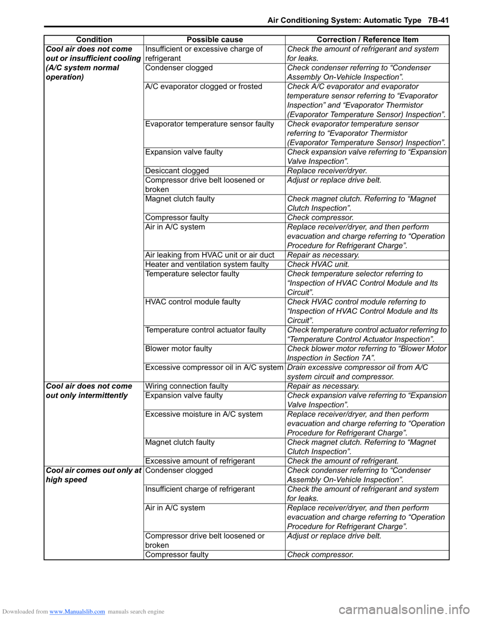
Cool air does not come
out or insufficient cooling
(A/C system normal
operation)Insufficient or excessive charge of
refrigerant
Check the amount of refrigerant and system
for leaks.
Condenser clogged Check condenser referring to “Condenser
Assembly On-Vehicle Inspection”.
A/C evaporator clogged or frosted Check A/C evaporator and evaporator
temperature sensor referring to “Evaporator
Inspection” and “Evaporator Thermistor
(Evaporator Temperature Sensor) Inspection”.
Evaporator temperature sensor faulty Check evaporator temperature sensor
referring to “Evaporator Thermistor
(Evaporator Temperature Sensor) Inspection”.
Expansion valve faulty Check expansion valve referring to “Expansion
Valve Inspection”.
Desiccant clogged Replace receiver/dryer.
Compressor drive belt loosened or
broken Adjust or replace drive belt.
Magnet clutch faulty Check magnet clutch. Referring to “Magnet
Clutch Inspection”.
Compressor faulty Check compressor.
Air in A/C system Replace receiver/dryer, and then perform
evacuation and charge referring to “Operation
Procedure for Refrigerant Charge”.
Air leaking from HVAC unit or air duct Repair as necessary.
Heater and ventilation system faulty Check HVAC unit.
Temperature selector faulty Check temperature selector referring to
“Inspection of HVAC Control Module and Its
Circuit”.
HVAC control module faulty Check HVAC control module referring to
“Inspection of HVAC Control Module and Its
Circuit”.
Temperature control actuator faulty Check temperature control actuator referring to
“Temperature Control Actuator Inspection”.
Blower motor faulty Check blower motor referring to “Blower Motor
Inspection in Section 7A”.
Excessive compressor oil in A/C system Drain excessive compressor oil from A/C
system circuit and compressor.
Cool air does not come
out only intermittently Wiring connection faulty
Repair as necessary.
Expansion valve faulty Check expansion valve referring to “Expansion
Valve Inspection”.
Excessive moisture in A/C system Replace receiver/dryer, and then perform
evacuation and charge referring to “Operation
Procedure for Refrigerant Charge”.
Magnet clutch faulty Check magnet clutch. Referring to “Magnet
Clutch Inspection”.
Excessive amount of refrigerant Check the amount of refrigerant.
Cool air comes out only at
high speed Condenser clogged
Check condenser referring to “Condenser
Assembly On-Vehicle Inspection”.
Insufficient charge of refrigerant Check the amount of refrigerant and system
for leaks.
Air in A/C system Replace receiver/dryer, and then perform
evacuation and charge referring to “Operation
Procedure for Refrigerant Charge”.
Compressor drive belt loosened or
broken Adjust or replace drive belt.
Compressor faulty Check compressor.
Condition Possible cause Correction / Reference Item
Page 1021 of 1496
Downloaded from www.Manualslib.com manuals search engine Air Conditioning System: Automatic Type 7B-73
HVAC Unit Removal and InstallationS7RS0B7226003
Refer to “HVAC Unit Removal and Installation”.
Temperature Control Actuator Removal and
Installation
S7RS0B7226004
Removal1) Disconnect negative (–) cable at battery.
2) Remove steering column hol e cover from instrument
panel.
3) Remove foot duct from HVAC unit.
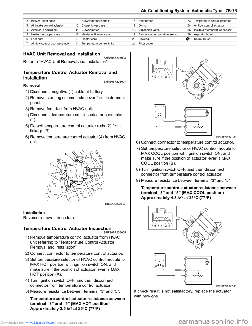
4) Disconnect temperature control actuator connector (1).
5) Detach temperature control actuator rods (2) from linkage (3).
6) Remove temperature control actuator (4) from HVAC unit.
Installation
Reverse removal procedure.
Temperature Control Actuator InspectionS7RS0B7226005
1) Remove temperature control actuator from HVAC unit referring to “Temperature Control Actuator
Removal and Installation”.
2) Connect connector to temperature control actuator.
3) Set temperature selector of HVAC control module to MAX HOT position with ignition switch ON, and
make sure if the position of actuator lever is MAX
HOT position (A).
4) Turn ignition switch OFF, and then disconnect connector from temperature control actuator.
5) Measure resistance between terminal “3” and “5”.
Temperature control actuator resistance between
terminal “3” and “5” (MAX HOT position)
Approximately 2.5 k Ω at 25 °C (77 °F) 6) Connect connector to tem
perature control actuator.
7) Set temperature selector of HVAC control module to MAX COOL position with ignition switch ON, and
make sure if the position of actuator lever is MAX
COOL position (B).
8) Turn ignition switch OFF, and then disconnect connector from temperature control actuator.
9) Measure resistance between terminal “3” and “5”
Temperature control actuator resistance between
terminal “3” and “5” (MAX COOL position)
Approximately 4.8 k Ω at 25 °C (77 °F)
If check result is not satisfactory, replace the actuator
with new one.
2. Blower upper case 9. Blower motor controller 16. Evaporator 23. Temperature control actuator
3. Air intake control actuator 10. Blower lower case 17. O-ring24. Air flow control actuator
4. Air filter (if equipped) 11. Blower motor 18. Expansion valve25. Inside air temperature sensor
5. Heater unit upper case 12. Heater unit lower case 19. Evaporator temperature sensor 26. Aspirator hose
6. Foot duct 13. Heater core 20. Packing : Do not reuse.
7. Air flow control door assembly 14. Temperature control links 21. Filter cover
1
2
2
3
4
I5RS0A722020-02
I5RS0A722021-03
I5RS0A722022-03
Page 1169 of 1496

Downloaded from www.Manualslib.com manuals search engine Table of Contents 9-iii
Door Switch (Front / Rear Door) Inspection ...... 9C-17
Rear End Door Switch Inspection ..................... 9C-17
Outside Air Temperature Sensor Removal and Installation (If Equipped) .......................... 9C-17
Outside Air Temperature Sensor Inspection (If Equipped) ................................................... 9C-17
Instrument Panel Removal and Installation....... 9C-18
Information Display (Clock) Removal and Installation ....................................................... 9C-19
Audio Unit Removal and In stallation ................. 9C-19
Front Speaker Removal and Installation ........... 9C-19
Rear Speaker Removal and Installation............ 9C-20
Horn Removal and Installation .......................... 9C-20
Horn Inspection ................................................. 9C-20
Horn Relay Inspection ....................................... 9C-20
Antenna Amplifier Removal and Installation ..... 9C-21
Remote Audio Control Switch Removal and Installation (If Equipped) ................................. 9C-21
Remote Audio Control Switch Inspection (If Equipped)........................................................ 9C-22
Vehicle Speed Signal Inspection (For Audio Unit) (If Equipped) ........................................... 9C-22
Specifications ..................................................... 9C-22
Tightening Torque Specifications ...................... 9C-22
Wipers / Washers............ ......................... 9D-1
Diagnostic Information and Procedures ............ 9D-1
Front Wiper and Washer Symptom Diagnosis .... 9D-1
Rear Wiper and Washer Symptom Diagnosis..... 9D-1
Repair Instructions .............................................. 9D-2 Wipers and Washers Components ..................... 9D-2
Washer Tank and Washer Pump Removal and Installation .................................................. 9D-3
Washer Pump Inspection .................................... 9D-3
Windshield Wiper Removal and Installation ........ 9D-4
Windshield Wiper Motor Inspection..................... 9D-5
Rear Wiper Removal and Installation.................. 9D-6
Rear Wiper Motor Inspection .............................. 9D-7
Windshield Wiper and Washer Switch Removal and Installation................................... 9D-7
Windshield Wiper and Washer Switch Inspection.......................................................... 9D-8
Rear Wiper and Washer Switch Removal and Installation ......................................................... 9D-9
Rear Wiper and Washer Switch Inspection......... 9D-9
Rear Wiper Relay Removal and Installation ..... 9D-10
Rear Wiper Relay Inspection ............................ 9D-10
Specifications ..................................................... 9D-10
Tightening Torque Specifications ...................... 9D-10
Glass / Windows / Mirrors.. ..................... 9E-1
General Description ............................................. 9E-1
Rear End Door Window Defogger System Description ........................................................ 9E-1
Windshield Construction ..................................... 9E-1
Diagnostic Information and Procedures ............ 9E-2 Rear End door Window Defogger Symptom Diagnosis .......................................................... 9E-2 Power Window Control System Symptom
Diagnosis .......................................................... 9E-2
Power Door Mirror Control System Symptom Diagnosis .......................................................... 9E-3
Door Mirror Heater Symptom Diagnosis (If
Equipped) .......................................................... 9E-3
Repair Instructions ........... ................................... 9E-4
Windshield Removal and In stallation .................. 9E-4
Front Door Window Components ........................ 9E-8
Front Door Glass Removal and Installation ........ 9E-8
Front Door Window Re gulator Removal and
Installation ......................................................... 9E-9
Front Door Window Regula tor Inspection ......... 9E-10
Rear Door Window Components ...................... 9E-10
Rear Door Glass Removal and Installation ....... 9E-11
Rear Door Window Regulator Removal and Installation ....................................................... 9E-12
Rear Door Window Regulato r Inspection .......... 9E-12
Rear End Door Window Components ............... 9E-13
Rear End Door Glass Removal and Installation ....................................................... 9E-13
Rear End Door Window Defogger Switch Inspection ........................................................ 9E-14
Rear End Door Window Defogger Relay Inspection ........................................................ 9E-14
Rear End Door Window Defogger Wire Inspection ........................................................ 9E-15
Rear End Door Window Defogger Wire
Repair.............................................................. 9E-15
Power Window Main Switch Inspection ............ 9E-16
Power Window Sub Switch Inspection .............. 9E-17
Door Mirror Components.. ................................. 9E-18
Door Mirror Removal and In stallation................ 9E-18
Power Door Mirror Switch Inspection ................ 9E-18
Power Door Mirror Actuator Inspection ............. 9E-19
Door Mirror Heater Switch Inspection (If Equipped) ........................................................ 9E-19
Door Mirror Heater Inspec tion (If Equipped) ..... 9E-19
Special Tools and Equipmen t ........................... 9E-19
Recommended Service Material ....................... 9E-19
Security and Locks......... ..........................9F-1
General Description ............................................. 9F-1
Key Coding Construction .................................... 9F-1
Rear End Door Opener System Description ....... 9F-1
Component Location ............ ............................... 9F-2
Power Door Lock and Keyless Entry System
Component Location ......................................... 9F-2
Diagnostic Information and Procedures ............ 9F-3 Power Door Lock System Symptom Diagnosis .......................................................... 9F-3
Power Door Lock System Operation Inspection .......................................................... 9F-3
Keyless Entry System Symptom Diagnosis (If
Equipped) .......................................................... 9F-4
Keyless Entry System Operation Inspection ....... 9F-5
Door Lock Function of Keyless Start System Symptom Diagnosis (If Equipped)..................... 9F-5
Page 1173 of 1496
Downloaded from www.Manualslib.com manuals search engine Wiring Systems: 9A-2
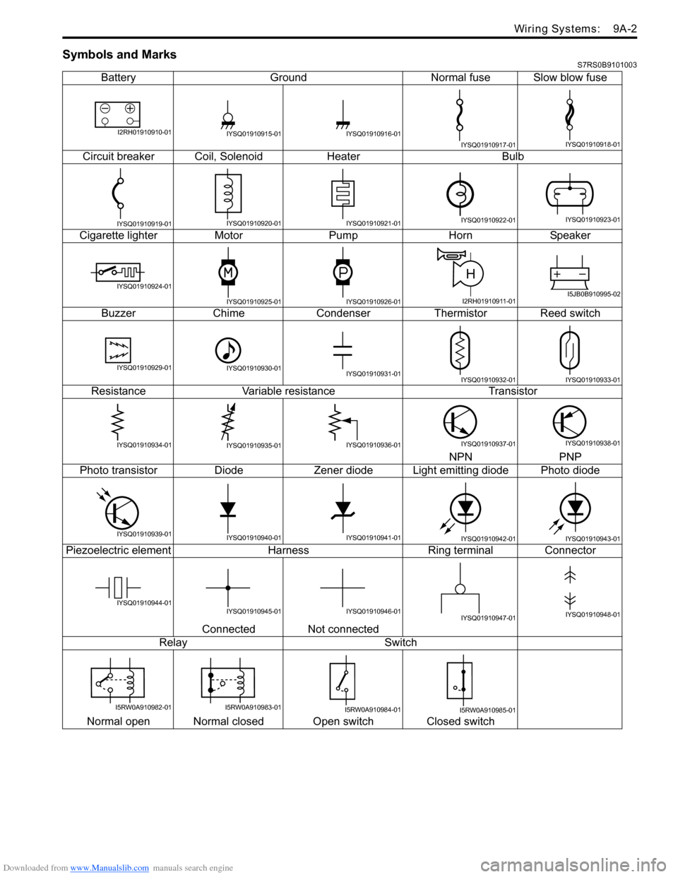
Symbols and MarksS7RS0B9101003
BatteryGroundNormal fuse Slow blow fuse
Circuit breaker Coil, SolenoidHeater Bulb
Cigarette lighter MotorPump HornSpeaker
Buzzer ChimeCondenser Thermistor Reed switch
Resistance Variable resistance Transistor
NPN PNP
Photo transistor DiodeZener diode L ight emitting diode Photo diode
Piezoelectric element Harness Ring terminal Connector
Connected Not connected
Relay Switch
Normal open Normal closed Open switch Closed switch
I2RH01910910-01IYSQ01910915-01IYSQ01910916-01
IYSQ01910917-01IYSQ01910918-01
IYSQ01910919-01IYSQ01910920-01IYSQ01910921-01IYSQ01910922-01IYSQ01910923-01
IYSQ01910924-01
IYSQ01910925-01IYSQ01910926-01
H
I2RH01910911-01I5JB0B910995-02
IYSQ01910929-01IYSQ01910930-01IYSQ01910931-01IYSQ01910932-01IYSQ01910933-01
IYSQ01910934-01IYSQ01910935-01IYSQ01910936-01IYSQ01910937-01IYSQ01910938-01
IYSQ01910939-01IYSQ01910940-01IYSQ01910941-01IYSQ01910942-01IYSQ01910943-01
IYSQ01910944-01IYSQ01910945-01IYSQ01910946-01IYSQ01910947-01IYSQ01910948-01
I5RW0A910982-01I5RW0A910983-01I5RW0A910984-01I5RW0A910985-01
Page 1207 of 1496
Downloaded from www.Manualslib.com manuals search engine Wiring Systems: 9A-36
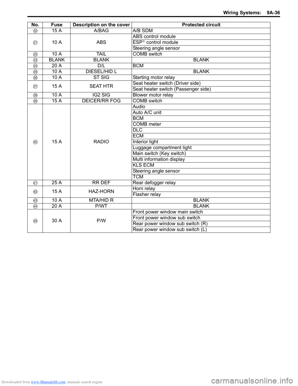
15 AA/BAG A/B SDM
10 A ABSABS control module
ESP
® control module
Steering angle sensor
10 A TAIL COMB switch
BLANK BLANK BLANK 20 A D/L BCM
10 A DIESEL/HID L BLANK
10 A ST SIG Starting motor relay
15 A SEAT HTR Seat heater switch (Driver side)
Seat heater switch (Passenger side)
10 A IG2 SIG Blower motor relay
15 A DEICER/RR FOG COMB switch
15 A RADIO Audio
Auto A/C unit
BCM
COMB meter
DLC
ECM
Interior light
Luggage compartment light
Main switch (Key switch)
Multi information display
KLS ECM
Steering angle sensor
TCM
25 A RR DEF Rear defogger relay
15 A HAZ-HORN Horn relay
Flasher relay
10 A MTA/HID R BLANK
20 A P/WT BLANK
30 A P/W Front power window main switch
Front power window sub switch
Rear power window sub switch (R)
Rear power window sub switch (L)
No. Fuse Description on the cover Protected circuit