2006 SUZUKI SWIFT heated
[x] Cancel search: heatedPage 893 of 1496

Downloaded from www.Manualslib.com manuals search engine Power Assisted Steering System: 6C-11
Scan Tool DataS7RS0B6304006
NOTE
When P/S motor is cold condition (that is, armature coil of P/S motor is not heated), normal value with
asterisk (*) mark in the following table is displayed on scan tool.
�) C1143 P/S motor circuit current too
high Measured motor drive current is
more than 50 A.
• P/S motor circuit
• P/S motor
• P/S control module1 driving
cycle
�) C1145 P/S motor circuit current too
low Measured motor drive current is
less than 2 A continuously for
more than 3 seconds even though
target motor drive current is more
than 4 A.
or
Measured motor drive current is
less than 0.8 A for total 1 second
even though motor control duty is
more than 90% while target motor
drive current is less than 8 A. 1 driving
cycle
�) C1153 P/S control module power
supply circuit Power supply voltage of P/S
control module is less than 9 V for
5 seconds continuously. • P/S control module power
supply circuit
• Undercharged Battery
• P/S control module 1 driving
cycle
�) C1155 P/S control module internal
failure Internal memory (EEPROM) is
data error.
• P/S control moduleNot
applicable
Internal circuit is faulty.
or
Power supply voltage of P/S
control module exceeded 17.5 V. • Overcharged Battery
• P/S control module
1 driving
cycle
DTC No. Detecting item
Detecting condition
(DTC will set when detecting) Trouble area MIL
Scan tool data
Vehicle conditionNormal condition
�) Battery Voltage
Ignition switch ON 10 – 14 V
�) TQS Power Supply 10 – 14 V
�) TQS Main Torque Engine running at idle speed Steering wheel at fully turned to left –9.4 – 0 N
⋅m
Steering wheel at free 0 N⋅m
Steering wheel at fully turned to right 0 – 9.4 N ⋅m
�) TQS Sub Torque Engine running at idle speed Steering wheel at fully turned to left –9.4 – 0 N
⋅m
Steering wheel at free 0 N⋅m
Steering wheel at fully turned to right 0 – 9.4 N ⋅m
�) Assist Torque Engine running at idle speed Steering wheel at fully turned to left –9.4 – 0 N
⋅m
Steering wheel at free 0 N⋅m
Steering wheel at fully turned to right 0 – 9.4 N ⋅m
�) Motor Control Engine running at idle speed Steering wheel at free
0 A
Steering wheel at fully turned to left or right *35 – 45 A
�) Motor Monitor Engine running at idle speed Steering wheel at free
0 A
Steering wheel at fully turned to left or right *35 – 45 A
�) Vehicle Speed Engine running and vehicle at stop 0 km/h
�) Engine Speed Engine running at idle speed after warming up 700 ± 50 rpm
�) Motor Volt Engine running at idle speed Steering wheel at free
0.8 – 1 V
Steering wheel at fully turned to right About 5 V
�) Ignition switch Ignition switch ON ON
Page 952 of 1496

Downloaded from www.Manualslib.com manuals search engine 7B-4 Air Conditioning System: Manual Type
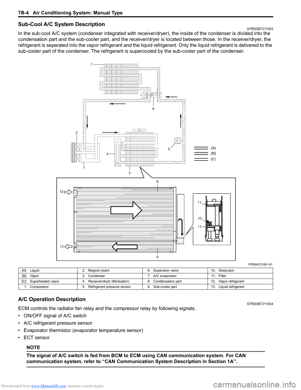
Sub-Cool A/C System DescriptionS7RS0B7211003
In the sub-cool A/C system (condenser integrated with receiver/dryer), the inside of the condenser is divided into the
condensation part and the sub-cooler part, and the receiver/dryer is located between those. In the receiver/dryer, the
refrigerant is separated into the vapor refrigerant and the liqui d refrigerant. Only the liquid refrigerant is delivered to the
sub-cooler part of the condenser. The refrigerant is supercooled by the sub-cooler part of the condenser.
A/C Operation DescriptionS7RS0B7211004
ECM controls the radiator fan relay and the compressor relay by following signals.
• ON/OFF signal of A/C switch
• A/C refrigerant pressure sensor
• Evaporator thermistor (evaporator temperature sensor)
• ECT sensor
NOTE
The signal of A/C swit ch is fed from BCM to ECM usin g CAN communication system. For CAN
communication system, refer to “CAN Communication System Description in Section 1A”.
I7RS0A721001-01
[A]: Liquid 2. Magnet clutch 6. Expansion valve10. Desiccant
[B]: Vapor 3. Condenser 7. A/C evaporator11. Filter
[C]: Superheated vapor 4. Receiver/dryer (Modulator) 8. Condensation part12. Vapor refrigerant
1. Compressor 5. Refrigerant pressure sensor 9. Sub-cooler part 13. Liquid refrigerant
Page 967 of 1496

Downloaded from www.Manualslib.com manuals search engine Air Conditioning System: Manual Type 7B-19
Charge
CAUTION!
• Because the sight glass is not used for this A/C system, do not perform an additional
charge to the A/C system. To charge the
proper amount of refrigerant, recover and
evacuate the A/C system first. And then,
charge the proper amount of refrigerant
into the A/C system.
• Always charge refrigerant through low pressure side of A/C system after the initial
charge is performed from the high
pressure side with the engine stopped.
• Never charge refrigerant through high pressure side of A/C system with engine
running.
• Do not charge refrigerant while compressor is hot.
• When installing tap valve to refrigerant container to make a hole there through,
carefully follow dire ctions given by
manufacturer.
• A pressure gauge should always be used before and during refrigerant charge.
• The refrigerant container should be emptied of refrigerant when discarding it.
• The refrigerant container should not be heated up to 40 °C (104 °F) or over.
• Refrigerant container should not be reversed in direction during refrigerant
charge. Reversing in direction causes
liquid refrigerant to enter compressor,
causing troubles, such as compression of
liquid refrigerant and the like.
NOTE
The air conditioning system contains HFC-
134a (R-134a).
Described here is a method to charge the air
conditioning system with refrigerant from the
refrigerant service container.
When charging refrigerant recovered by
using the refrigerant and recycling
equipment (when recycling refrigerant),
follow the procedure described in the
equipment manufacturer’s instruction
manual.
Charge proper amount of refrigerant accurately in
accordance with the following procedure.
Specified amount of refrigerant
370 ± 20 g (13.0 ± 0.7 oz)
The initial charge of the A/C system is performed
through the high pressure side with the engine stopped.
And next, this method must be followed by charging from
the low pressure side with the engine running.
1) Check if hoses are routed properly after evacuating the system.
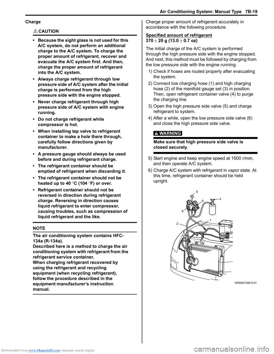
2) Connect low charging hose (1) and high charging hose (2) of the manifold gauge set (3) in position.
Then, open refrigerant container valve (4) to purge
the charging line.
3) Open the high pressure side valve (5) and charge refrigerant to system.
4) After a while, open the low pressure side valve (6) and close the high pressure side valve.
WARNING!
Make sure that high pressure side valve is
closed securely.
5) Start engine and keep engine speed at 1500 r/min, and then operate A/C system.
6) Charge A/C system with refrigerant in vapor state. At this time, refrigerant container should be held
upright.
1
2 6 3
5 4
I4RS0A720015-01
Page 1182 of 1496

Downloaded from www.Manualslib.com manuals search engine 9A-11 Wiring Systems:
C: Engine harnessNo./Color Connective position No./Color Connective positionC01/GRY IAC valve C22/- Generator #2
C02/GRY IG Coil #1 C23/BLK Starting motor #1
C03/GRY IG Coil #2 C24/- Starting motor #2
C04/GRY Fuel injector #1 C25/GR Y VSS (Vehicle speed sensor)
C05/GRY Fuel injector #2 C26/GRY Knock sensor
C06/GRY Fuel injector #3 C27/BLU (A/
T) Input shaft speed sensor
C07/GRY Fuel injector #4 C28/GRY
(A/T) Trans axle range sensor
C08/BLK or GRY CMP sensor C29/GRY
(A/T) Shift solenoid
C09/BLK ECT sensor C30/BLK
(M/T) Back-up light switch
C10/GRY EGR stepper motor C31/- Main fuse box C11/BLK Throttle position sensor C32/GRY
(IF EQPD) Current sensor
C12/BLK MAP sensor C33/- Main fuse box
C13/BLK MAF sensor C34/N (A/T) TCM
C14/BLK EVAP canister purge valve C35/N (A/T) TCM
C15/GRY Heated oxygen sensor #1 C36/N Main harness (To E24)
C16/GRN Heated oxygen sensor #2 C37/GRY ECM C17/BLK A/C compressor C38/- Weld splice C18/N Oil pressure switch C39/- Weld splice
C19/BLU VVT solenoid C40/- Weld splice
C20/GRY CKP sensor C41/- Weld splice
C21/GRY or BLK Generator #1
Page 1184 of 1496

Downloaded from www.Manualslib.com manuals search engine 9A-13 Wiring Systems:
C: Engine harness
D: Oil pressure switch wireNo./Color Connective position No./Color Connective position
C02/GRY IG Coil #1 C24/- Starting motor #2
C03/GRY IG Coil #2 C23/BLK Starting motor #1
C04/GRY Fuel injector #1 C25/GRY
(A/T) VSS (Vehicle speed sensor)
C05/GRY Fuel injector #2 C26/GRY Knock shaft speed sensor
C06/GRY Fuel injector #3 C27/BLU (A/
T) Input shaft speed sensor
C07/GRY Fuel injector #4 C28/GRY
(A/T) Trans axle range sensor
C08/BLK CMP sensor C29/GRY
(A/T) Shift solenoid
C09/BLK ECT sensor C30/BLK
(M/T) Back-up light switch
C10/GRY EGR stepper motor C31/- Main fuse box C12/BLK MAP sensor C32/GRY Current sensor
C13/BLK MAF sensor C33/- Main fuse box
C14/BLK EVAP canister purge valve C34/N (A/T) TCM
C15/BLK Heated oxygen sensor #1 C35/N (A/T) TCM
C16/GRN Heated oxygen sensor #2 C36/N Main harness (To E24) C17/BLK A/C compressor C37/GRY ECM C18/N Oil pressure switch wire (To D02) C38/- Weld splice
C19/BLU VVT solenoid C39/- Weld splice
C20/GRY CKP sensor C40/- Weld splice C21/BLK Generator #1 C42/BLK Electric throttle body C22/- Generator #2
No./Color Connective position No./ColorConnective position
D01/N Oil pressure switch D02/GRY Engine harness (To C18)
Page 1206 of 1496

Downloaded from www.Manualslib.com manuals search engine 9A-35 Wiring Systems:
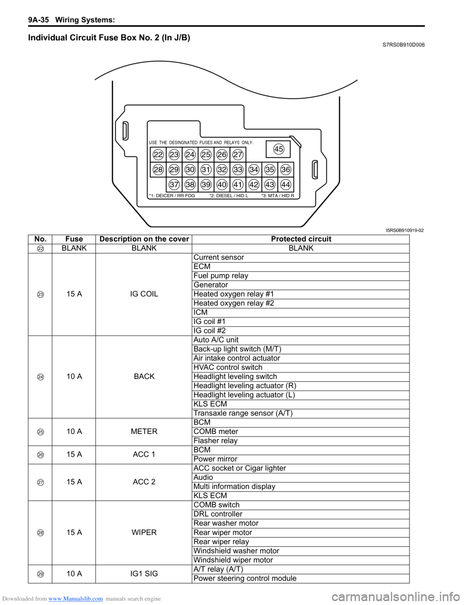
Individual Circuit Fuse Box No. 2 (In J/B)S7RS0B910D006
22
28
23
29
37
24
30
38
25
31
39
26
32
40
27
33
41
34
42
35
43
36
44
45USE THE DESINGNATED FUSES AND RELAYS ONLY.
*1: DEICER / RR FOG *2: DIESEL / HID L *3: MTA / HID R
I5RS0B910919-02
No. Fuse Description on the coverProtected circuit
BLANK BLANK BLANK
15 A IG COILCurrent sensor
ECM
Fuel pump relay
Generator
Heated oxygen relay #1
Heated oxygen relay #2
ICM
IG coil #1
IG coil #2
10 A BACKAuto A/C unit
Back-up light switch (M/T)
Air intake control actuator
HVAC control switch
Headlight leveling switch
Headlight leveling actuator (R)
Headlight leveling actuator (L)
KLS ECM
Transaxle range sensor (A/T)
10 A METERBCM
COMB meter
Flasher relay
15 A ACC 1BCM
Power mirror
15 A ACC 2ACC socket or Cigar lighter
Audio
Multi information display
KLS ECM
15 A WIPERCOMB switch
DRL controller
Rear washer motor
Rear wiper motor
Rear wiper relay
Windshield washer motor
Windshield wiper motor
10 A IG1 SIGA/T relay (A/T)
Power steering control module
Page 1221 of 1496

Downloaded from www.Manualslib.com manuals search engine Wiring Systems: 9A-50
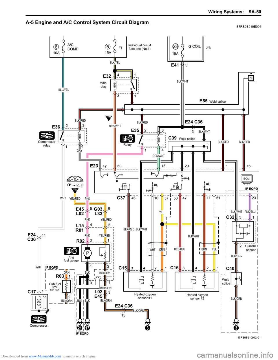
A-5 Engine and A/C Control System Circuit DiagramS7RS0B910E006
YEL/RED
E45L02 G03
L33
L02
E4558
L15
R0142
PNKYEL/RED
P
PNKYEL/RED
31
3
3 1
E24 C36
BLK/ORN
BLK/ORN
BLK/ORN
BLK/ORN
3
15
BLK
42
R02
1
2
R03
And
fuel gauge
Sub fuel level
sensor
Main
relay
1BLK/WHT
BLK/WHT
C39Weld splice Weld splice
E55
GRN/WHT
IG COILJ/B5
15A
FI
BLK/YEL
E324
32
1 15A
23
BRN/WHT
BW
YR
6
10A
A/C
COMP
Compressor
relay
E36
Relay
BLU/YEL
Compressor
C171
E415
E24 C36
3
E24
C3611
BLK/WHT
C15 C16
Heated oxygen
sensor #1
BLK/RED
WHT
Heated oxygensensor #2
BRN
BLK/WHT
RED/BLU
C37
34213421
4610574711
YEL
5123PNK
ECM
41 3
2
WHT
WHT
BLK/REDBLK/RED
BLK/RED
E23476015291
GRY
E3523
1
4
ORN
BLKBLKBLK/ORN
ORN
YEL
50
BLK/RED
16
17213
Individual circuit
fuse box (No.1)
BLK/ORN
BLK/ORN
BLK/WHTPNK/BLU
IF EQPD
IF EQPD IF EQPD
Weld
splice
C40 C32
Current
sensor
3
2 1
"C-3"
I7RS0B910912-01