2006 SUZUKI SWIFT Servo
[x] Cancel search: ServoPage 512 of 1496
Downloaded from www.Manualslib.com manuals search engine 4A-14 Brake Control System and Diagnosis:
6) Fill reservoir with specified fluid.
7) After completing the work, bleed air from brake and clutch system referring to “Air Bleeding of Brake
System” and “Air Bleeding of Clutch System in
Section 5C” (M/T model).
8) Install cowl top panel referring to “Cowl Top Components in Section 9K”.
9) Install windshield wiper referring to “Windshield
Wiper Removal and Insta llation in Section 9D”.
10) Perform brake test and check each installed part for fluid leakage.
Master Cylinder Assembly Disassembly and
Assembly
S7RS0B4106013
Disassembly
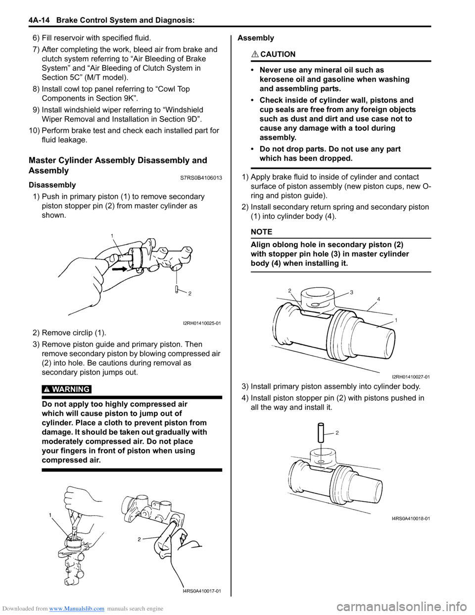
1) Push in primary piston (1) to remove secondary
piston stopper pin (2) from master cylinder as
shown.
2) Remove circlip (1).
3) Remove piston guide and primary piston. Then remove secondary piston by blowing compressed air
(2) into hole. Be cautions during removal as
secondary piston jumps out.
WARNING!
Do not apply too highly compressed air
which will cause piston to jump out of
cylinder. Place a cloth to prevent piston from
damage. It should be taken out gradually with
moderately compressed air. Do not place
your fingers in front of piston when using
compressed air.
Assembly
CAUTION!
• Never use any mineral oil such as kerosene oil and gasoline when washing
and assembling parts.
• Check inside of cylinder wall, pistons and cup seals are free from any foreign objects
such as dust and dirt and use case not to
cause any damage with a tool during
assembly.
• Do not drop parts. Do not use any part which has been dropped.
1) Apply brake fluid to inside of cylinder and contact surface of piston assembly (new piston cups, new O-
ring and piston guide).
2) Install secondary return spring and secondary piston (1) into cylinder body (4).
NOTE
Align oblong hole in secondary piston (2)
with stopper pin hole (3) in master cylinder
body (4) when installing it.
3) Install primary piston assembly into cylinder body.
4) Install piston stopper pin (2) with pistons pushed in all the way and install it.
I2RH01410025-01
I4RS0A410017-01
I2RH01410027-01
I4RS0A410018-01
Page 515 of 1496
Downloaded from www.Manualslib.com manuals search engine Brake Control System and Diagnosis: 4A-17
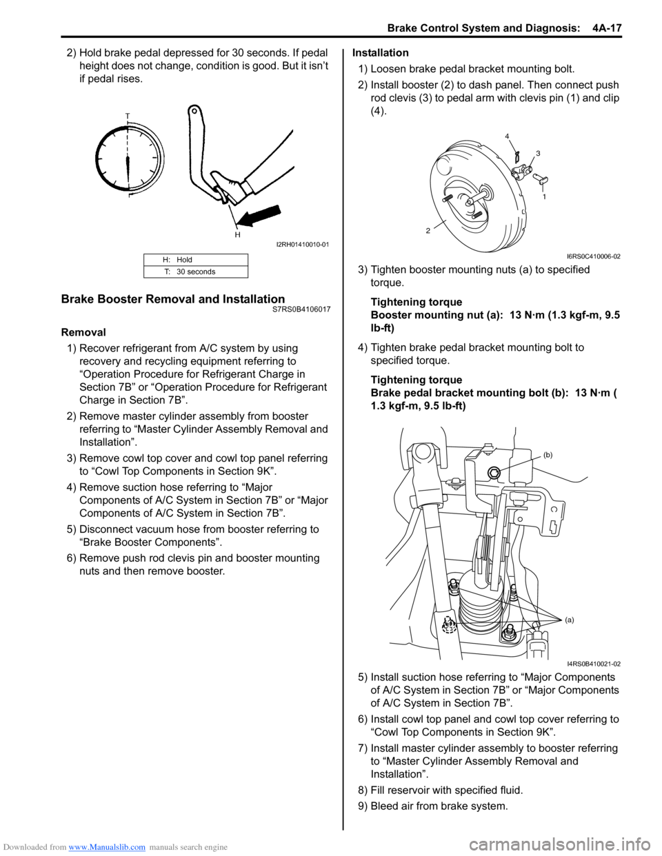
2) Hold brake pedal depressed for 30 seconds. If pedal height does not change, condition is good. But it isn’t
if pedal rises.
Brake Booster Removal and InstallationS7RS0B4106017
Removal
1) Recover refrigerant from A/C system by using recovery and recycling equipment referring to
“Operation Procedure for Refrigerant Charge in
Section 7B” or “Operation Procedure for Refrigerant
Charge in Section 7B”.
2) Remove master cylinder assembly from booster referring to “Master Cylin der Assembly Removal and
Installation”.
3) Remove cowl top cover and cowl top panel referring to “Cowl Top Components in Section 9K”.
4) Remove suction hose referring to “Major Components of A/C System in Section 7B” or “Major
Components of A/C System in Section 7B”.
5) Disconnect vacuum hose from booster referring to “Brake Booster Components”.
6) Remove push rod clevis pin and booster mounting nuts and then remove booster. Installation
1) Loosen brake pedal bracket mounting bolt.
2) Install booster (2) to dash panel. Then connect push rod clevis (3) to pedal arm with clevis pin (1) and clip
(4).
3) Tighten booster mounting nuts (a) to specified torque.
Tightening torque
Booster mounting nut (a): 13 N·m (1.3 kgf-m, 9.5
lb-ft)
4) Tighten brake pedal bracket mounting bolt to specified torque.
Tightening torque
Brake pedal bracket mounting bolt (b): 13 N·m (
1.3 kgf-m, 9.5 lb-ft)
5) Install suction hose referring to “Major Components of A/C System in Section 7B” or “Major Components
of A/C System in Section 7B”.
6) Install cowl top panel and cowl top cover referring to
“Cowl Top Components in Section 9K”.
7) Install master cylinder assembly to booster referring to “Master Cylinder Assembly Removal and
Installation”.
8) Fill reservoir with specified fluid.
9) Bleed air from brake system.
H: Hold
T: 30 seconds
I2RH01410010-01
1
2 4
3
I6RS0C410006-02
(b)
(a)
I4RS0B410021-02
Page 516 of 1496
Downloaded from www.Manualslib.com manuals search engine 4A-18 Brake Control System and Diagnosis:
10) Check pedal height and play referring to “Brake Pedal Free Height Inspection” and “Brake Pedal
Play Inspection”.
11) Check each installed part for fluid leakage and perform brake test.
12) Evacuate and charge refrigerant by referring to “Evacuating of A/C Syst em” and “Procedure of
Charging” under “Operation Procedure for
Refrigerant Charge in Section 7B” or “Operation
Procedure for Refrigerant Charge in Section 7B”.
Brake Booster Inspection and AdjustmentS7RS0B4106018
Installation Position of Push Rod
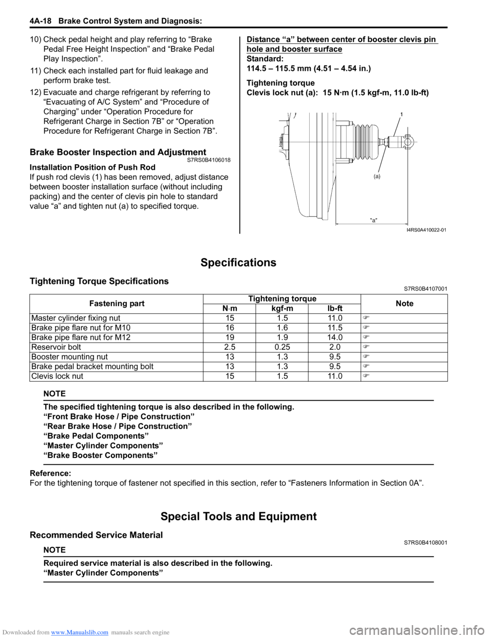
If push rod clevis (1) has b een removed, adjust distance
between booster installation surface (without including
packing) and the center of clevis pin hole to standard
value “a” and tighten nut (a) to specified torque. Distance “a” between center of booster clevis pin
hole and booster surface
Standard:
114.5 – 115.5 mm (4.51 – 4.54 in.)
Tightening torque
Clevis lock nut (a): 15 N·m (1.5 kgf-m, 11.0 lb-ft)
Specifications
Tightening Torque SpecificationsS7RS0B4107001
NOTE
The specified tightening torque is also described in the following.
“Front Brake Hose / Pipe Construction”
“Rear Brake Hose / Pipe Construction”
“Brake Pedal Components”
“Master Cylinder Components”
“Brake Booster Components”
Reference:
For the tightening torque of fastener not specified in this
section, refer to “Fasteners Information in Section 0A”.
Special Tools and Equipment
Recommended Service MaterialS7RS0B4108001
NOTE
Required service material is also described in the following.
“Master Cylinder Components”
I4RS0A410022-01
Fastening part Tightening torque
Note
N ⋅mkgf-mlb-ft
Master cylinder fixing nut 15 1.5 11.0 �)
Brake pipe flare nut for M10 16 1.6 11.5 �)
Brake pipe flare nut for M12 19 1.9 14.0 �)
Reservoir bolt 2.5 0.25 2.0 �)
Booster mounting nut 13 1.3 9.5 �)
Brake pedal bracket mounting bolt 13 1.3 9.5 �)
Clevis lock nut 15 1.5 11.0 �)
Page 520 of 1496
Downloaded from www.Manualslib.com manuals search engine 4B-4 Front Brakes:
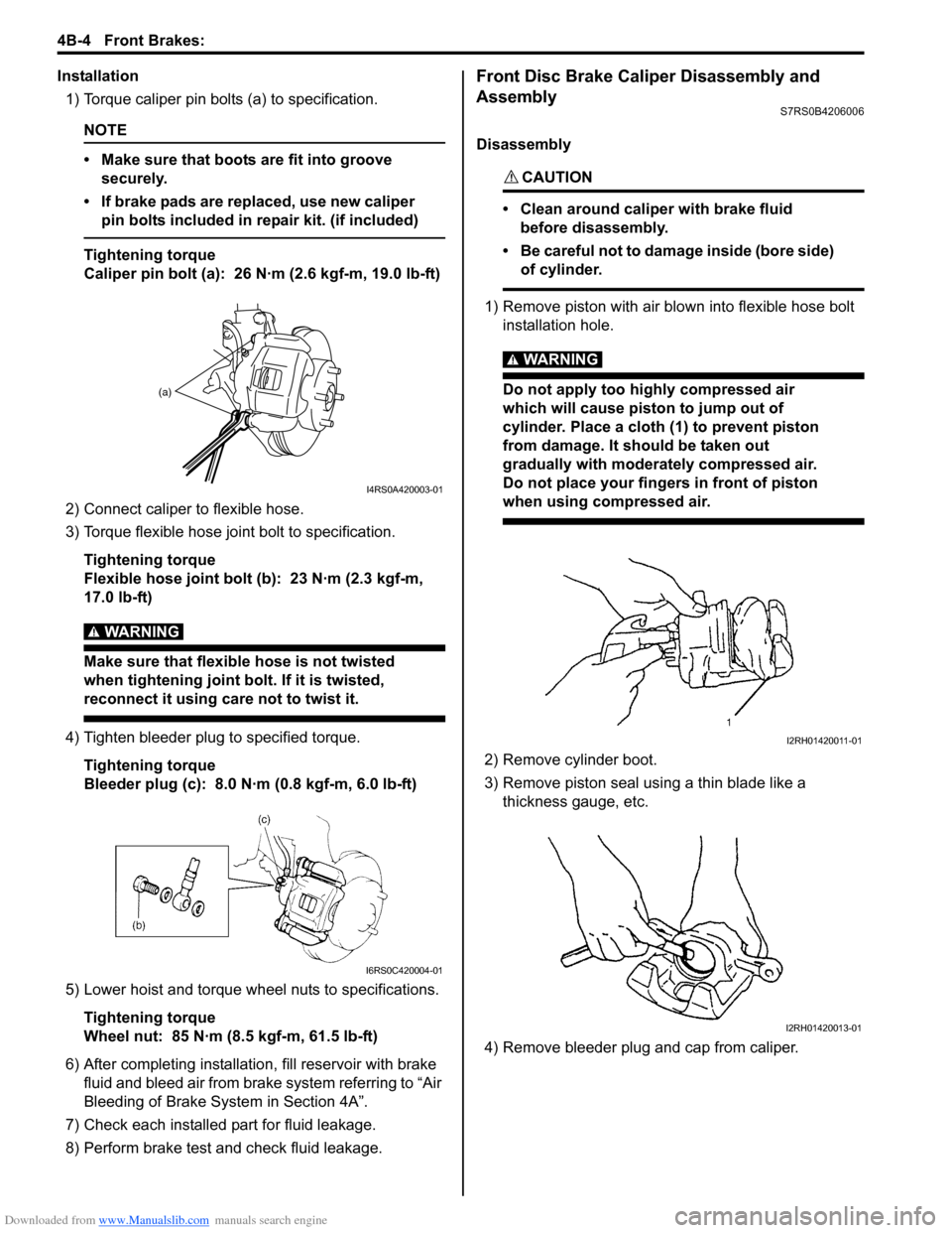
Installation1) Torque caliper pin bolts (a) to specification.
NOTE
• Make sure that boots are fit into groove securely.
• If brake pads are replaced, use new caliper pin bolts included in repair kit. (if included)
Tightening torque
Caliper pin bolt (a): 26 N·m (2.6 kgf-m, 19.0 lb-ft)
2) Connect caliper to flexible hose.
3) Torque flexible hose jo int bolt to specification.
Tightening torque
Flexible hose joint bolt (b): 23 N·m (2.3 kgf-m,
17.0 lb-ft)
WARNING!
Make sure that flexible hose is not twisted
when tightening joint bolt. If it is twisted,
reconnect it using care not to twist it.
4) Tighten bleeder plug to specified torque. Tightening torque
Bleeder plug (c): 8.0 N·m (0.8 kgf-m, 6.0 lb-ft)
5) Lower hoist and torque wheel nuts to specifications. Tightening torque
Wheel nut: 85 N·m (8.5 kgf-m, 61.5 lb-ft)
6) After completing installation, fill reservoir with brake
fluid and bleed air from brake system referring to “Air
Bleeding of Brake System in Section 4A”.
7) Check each installed part for fluid leakage.
8) Perform brake test and check fluid leakage.
Front Disc Brake Caliper Disassembly and
Assembly
S7RS0B4206006
Disassembly
CAUTION!
• Clean around caliper with brake fluid before disassembly.
• Be careful not to damage inside (bore side) of cylinder.
1) Remove piston with air blown into flexible hose bolt installation hole.
WARNING!
Do not apply too highly compressed air
which will cause piston to jump out of
cylinder. Place a cloth (1) to prevent piston
from damage. It should be taken out
gradually with moderately compressed air.
Do not place your fingers in front of piston
when using compressed air.
2) Remove cylinder boot.
3) Remove piston seal using a thin blade like a thickness gauge, etc.
4) Remove bleeder plug and cap from caliper.
(a)
I4RS0A420003-01
I6RS0C420004-01
I2RH01420011-01
I2RH01420013-01
Page 521 of 1496

Downloaded from www.Manualslib.com manuals search engine Front Brakes: 4B-5
Assembly
Assemble parts in reverse order of disassembly,
observing the following instructions.
CAUTION!
• Wash each part cleanly before installation in the same fluid as the one used in master
cylinder reservoir.
• Never use other fluid or thinner.
• Before installing piston seal or cylinder boot to cylinder, apply brake fluid to them.
• Install a new piston seal into groove in cylinder securely making sure that it is not
twisted.
• Before installing caliper to carrier, check for slid pin smooth movement in thrust
direction.
• After reassembling brake lines, bleed air from them.
• Install piston seal, boot and piston to caliper referring to the following instructions.
1) Replace with a new piston seal (1) at every overhaul. After applying rubber grease (included in repair kit)
or brake fluid, fit piston seal (1) into groove in
cylinder taking care not to twist it. 2) Before inserting piston (1) into cylinder, apply rubber
grease (included in repair kit) or brake fluid to new
boot “a” and install it onto piston as shown.
3) Fit boot as it is in figure into boot groove in cylinder with fingers.
4) Insert piston into cylinder by hand and fit boot in boot groove in piston.
NOTE
Check that boot is fitted in boot groove
securely all around piston and cylinder.
I2RH01420016-01
1
I2RH01420017-01
“A”: 1 grooved side directed cylinder side
“B”: 2 grooved side directed pad side
I4RS0A420006-01
I2RH01420019-01
I2RH01420020-01
Page 531 of 1496

Downloaded from www.Manualslib.com manuals search engine Rear Brakes: 4C-7
Assembly
CAUTION!
• Wash each part cleanly before installation in the same fluid as the one used in master
cylinder reservoir.
• Never use other fluid or thinner.
• Before installing caliper to brake caliper carrier, install slide pins with grease
applied into carrier hole and check for its
smooth movement in thrust direction.
• Before installing piston seal to cylinder, apply fluid to them.
• Install a piston seal into groove in cylinder securely making sure that it is not twisted.
1) Apply thread lock cement to shaft thread (6) of caliper.
“A”: Thread lock cement 99000–32110 (Thread
Lock Cement Super 1322)
2) Apply grease to inside of new shaft cover (1).
3) Install new shaft cover, leve r (2), washer (3), parking
nut (4) and return spring (5) to caliper.
Tightening torque
Parking nut (a): 27 N·m (2.7 kgf-m, 19.5 lb-ft) 4) Install bleeder plug and cap to caliper.
5) Install new piston seal to caliper.
6) Before inserting piston (2) into cylinder, install boot
(1) onto piston as shown.
7) Fit boot as it is in figure into boot groove in cylinder with fingers.
8) Turn brake caliper piston clockwise to obtain clearance between brake disc and pads.
NOTE
Check that boot is fitted in boot groove
securely all around piston.
Special tool
(A): 09945–16060
5
4, (a)
2
3
1
6, “A”
I6RS0C430016-01
[A]: Cylinder side
[B]: Brake pad side
[A] [B]
I6RS0B431017-01
I6RS0B431033-01
I6RS0B431018-01
Page 578 of 1496
Downloaded from www.Manualslib.com manuals search engine 4F-4 Electronic Stability Program:
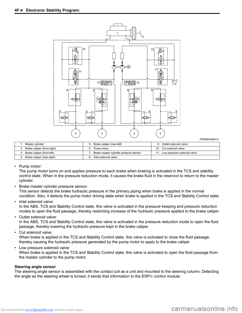
• Pump motor:The pump motor turns on and applies pressure to each brake when braking is activated in the TCS and stability
control state. When in the pressure reduction mode, it causes the brake fluid in the reservoir to return to the master
cylinder.
• Brake master cylinder pressure sensor: This sensor detects the brake hydraulic pressure in th e primary piping when brake is applied in the normal
condition. Also, it detects the pump motor driving state wh en brake is applied in the TCS and Stability Control state.
• Inlet solenoid valve: In the ABS, TCS and Stability Control stat e, this valve is activated in the pressure keeping and pressure reduction
modes to open the fluid passage, thereby restricting increase of the hydraulic pressure applied to the brake caliper.
• Outlet solenoid valve: In the ABS, TCS and Stability Control state, this valve is activated in the pressure reduction mode to open the fluid
passage, thereby lowering the hydraulic pressure kept in the brake caliper.
• Cut solenoid valve: When brake is applied in the TCS and Stability Control state, this valve is activated to close the fluid passage,
thereby causing the hydraulic pressure generated by the pump motor to apply to the brake caliper.
• Low pressure solenoid valve: When brake is applied in the TCS and Stab ility Control state, this valve is activated to open the fluid passage from
the master cylinder to the pump motor.
Steering angle sensor
The steering angle sensor is assembled with the contact co il as a unit and mounted to the steering column. Detecting
the angle as the steering wheel is turned, it sends that information to the ESP ® control module.
1
10 10
11 11
6
7
12 12
8 8 88
9 9 9
9
43 5 2
I7RS0B460002-01
1. Master cylinder 5. Brake caliper (rear-left)9. Outlet solenoid valve
2. Brake caliper (front-right) 6. Pump motor10. Cut solenoid valve
3. Brake caliper (front-left) 7. Brake master cylinder pressure sensor 11. Low pressure solenoid valve
4. Brake caliper (rear-right) 8. Inlet solenoid valve
Page 580 of 1496
Downloaded from www.Manualslib.com manuals search engine 4F-6 Electronic Stability Program:
Warning Lamp, Indicator Lamp DescriptionS7RS0B4601003
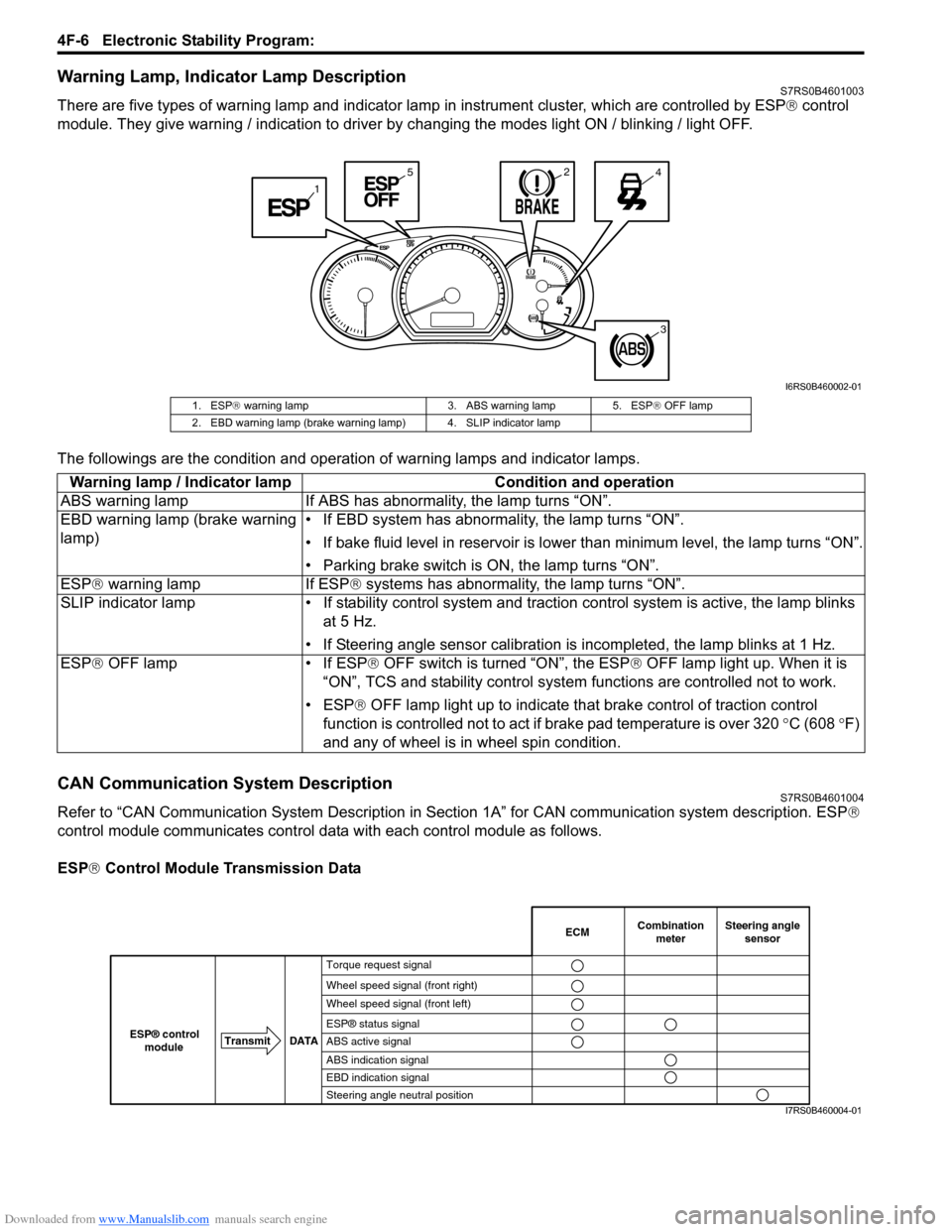
There are five types of warning lamp and indicator lamp in instrument cluster, which are controlled by ESP ® control
module. They give warning / indication to driver by changing the modes light ON / blinking / light OFF.
The followings are the condition and operation of warning lamps and indicator lamps.
CAN Communication System DescriptionS7RS0B4601004
Refer to “CAN Communication System Description in Section 1A” for CAN communication system description. ESP ®
control module communicates control data with each control module as follows.
ESP ® Control Module Transmission Data
1
245
3
I6RS0B460002-01
1. ESP ® warning lamp 3. ABS warning lamp 5. ESP ® OFF lamp
2. EBD warning lamp (brake warning lamp) 4. SLIP indicator lamp
Warning lamp / Indicator lamp Condition and operation
ABS warning lamp If ABS has abnor mality, the lamp turns “ON”.
EBD warning lamp (brake warning
lamp) • If EBD system has abnormality, the lamp turns “ON”.
• If bake fluid level in reservoir is lower
than minimum level, the lamp turns “ON”.
• Parking brake switch is ON, the lamp turns “ON”.
ESP ® warning lamp If ESP ® systems has abnormality, the lamp turns “ON”.
SLIP indicator lamp • If stability cont rol system and traction control system is active, the lamp blinks
at 5 Hz.
• If Steering angle sensor calibration is incompleted, the lamp blinks at 1 Hz.
ESP ® OFF lamp • If ESP ® OFF switch is turned “ON”, the ESP ® OFF lamp light up. When it is
“ON”, TCS and stability control system functions are controlled not to work.
• ESP® OFF lamp light up to indicate th at brake control of traction control
function is controlled not to act if brake pad temperature is over 320 °C (608 °F)
and any of wheel is in wheel spin condition.
Combination
meter
Transmit DATA
ESP® control
moduleECMSteering angle sensor
Torque request signal
Wheel speed signal (front right)
Wheel speed signal (front left)
ESP® status signal
ABS active signal
ABS indication signal
EBD indication signal
Steering angle neutral position
I7RS0B460004-01