2006 SUZUKI SWIFT Lever
[x] Cancel search: LeverPage 403 of 1496
Downloaded from www.Manualslib.com manuals search engine Starting System: 1I-2
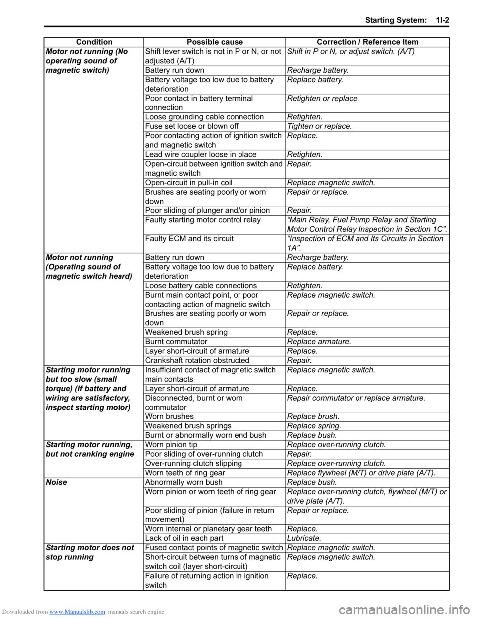
ConditionPossible cause Correction / Reference Item
Motor not running (No
operating sound of
magnetic switch) Shift lever switch is not in P or N, or not
adjusted (A/T)
Shift in P or N, or
adjust switch. (A/T)
Battery run down Recharge battery.
Battery voltage too low due to battery
deterioration Replace battery.
Poor contact in battery terminal
connection Retighten or replace.
Loose grounding cable connection Retighten.
Fuse set loose or blown off Tighten or replace.
Poor contacting action of ignition switch
and magnetic switch Replace.
Lead wire coupler loose in place Retighten.
Open-circuit between ignition switch and
magnetic switch Repair.
Open-circuit in pull-in coil Replace magnetic switch.
Brushes are seating poorly or worn
down Repair or replace.
Poor sliding of plunger and/or pinion Repair.
Faulty starting motor control relay “Main Relay, Fuel Pump Relay and Starting
Motor Control Relay Inspection in Section 1C”.
Faulty ECM and its circuit “Inspection of ECM and Its Circuits in Section
1A”.
Motor not running
(Operating sound of
magnetic switch heard) Battery run down
Recharge battery.
Battery voltage too low due to battery
deterioration Replace battery.
Loose battery cable connections Retighten.
Burnt main contact point, or poor
contacting action of magnetic switch Replace magnetic switch.
Brushes are seating poorly or worn
down Repair or replace.
Weakened brush spring Replace.
Burnt commutator Replace armature.
Layer short-circuit of armature Replace.
Crankshaft rotation obstructed Repair.
Starting motor running
but too slow (small
torque) (If battery and
wiring are satisfactory,
inspect starting motor) Insufficient contact
of magnetic switch
main contacts Replace magnetic switch.
Layer short-circuit of armature Replace.
Disconnected, burnt or worn
commutator Repair commutator or replace armature.
Worn brushes Replace brush.
Weakened brush springs Replace spring.
Burnt or abnormally worn end bush Replace bush.
Starting motor running,
but not cranking engine Worn pinion tip
Replace over-running clutch.
Poor sliding of over-running clutch Repair.
Over-running clutch slipping Replace over-running clutch.
Worn teeth of ring gear Replace flywheel (M/T) or drive plate (A/T).
Noise Abnormally worn bush Replace bush.
Worn pinion or worn teeth of ring gear Replace over-running clutch, flywheel (M/T) or
drive plate (A/T).
Poor sliding of pinion (failure in return
movement) Repair or replace.
Worn internal or planetary gear teeth Replace.
Lack of oil in each part Lubricate.
Starting motor does not
stop running Fused contact points of magnetic switch
Replace magnetic switch.
Short-circuit between turns of magnetic
switch coil (layer short-circuit) Replace magnetic switch.
Failure of returning action in ignition
switch Replace.
Page 406 of 1496
Downloaded from www.Manualslib.com manuals search engine 1I-5 Starting System:
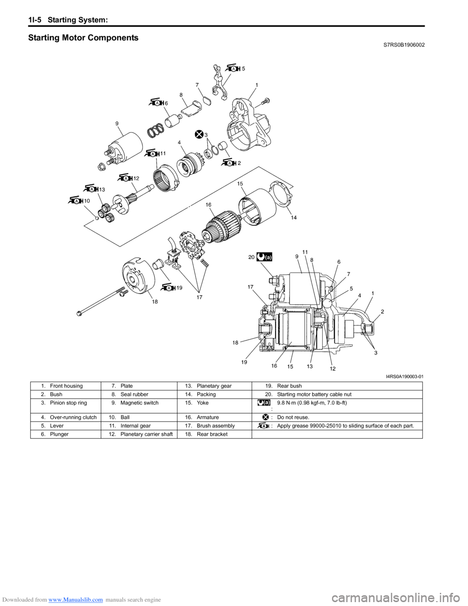
Starting Motor ComponentsS7RS0B1906002
I4RS0A190003-01
1. Front housing 7. Plate 13. Planetary gear 19. Rear bush
2. Bush 8. Seal rubber 14. Packing 20. Starting motor battery cable nut
3. Pinion stop ring 9. Magnetic switch 15. Yoke :9.8 N
⋅m (0.98 kgf-m, 7.0 lb-ft)
4. Over-running clutch 10. Ball 16. Armature: Do not reuse.
5. Lever 11. Internal gear 17. Brush assembly : Apply grease 99000-25010 to sliding surface of each part.
6. Plunger 12. Planetary carrier shaft 18. Rear bracket
Page 475 of 1496

Downloaded from www.Manualslib.com manuals search engine Wheels and Tires: 2D-8
Tire Mounting and DismountingS7RS0B2406004
CAUTION!
When installing tire which has arrow
indicating tire rotation direction to wheel,
make sure that this tire rotation direction is
same as actual tire rotation direction when
vehicle is moving forward. Otherwise, it is
not possible to install wheel with tire to
vehicle in specified direction.
Use a tire changing machine to mount or dismount tires.
Follow equipment manufacturer’s instructions. Do not
use hand tools or tire irons al one to change tires as they
may damage tire beads or wheel rim.
Rim bead seats should be cleaned with a wire brush or
coarse steel wool to remove lubricants, old rubber and
light rust. Before mounting or dismounting a tire, bead
area should be well lubricated with approved tire
lubricant.
After mounting, inflate to specified pressure shown on
tire placard so that beads are completely seated.
WARNING!
Do not stand over tire when inflating. Bead
may break when bead snaps over rim’s safety
hump and cause serious personal injury.
Do not exceed 330 kpa (47.9 psi) pressure
when inflating. If 330 kpa (47.9 psi) pressure
will not seat beads, deflate, re-lubricate and
reinflate.
Over inflation may cause bead to break and
cause serious personal injury.
Install valve core and inflate to proper pressure.
Tire RepairS7RS0B2406005
There are many different materials and techniques on
the market to repair tires. As not all of these work on all
types of tires, tire manufacturers have published detailed
instructions on how and when to repair tires. These
instructions can be obtained from each tire
manufacturer.
Tire Repair for Emergency Repaired-Tire with
Sealant
S7RS0B2406006
WARNING!
Be sure to observe “Precaution for
Emergency Flat Tire Repair Kit”. Otherwise,
your health may be ruined.
1) Remove flat tire repair sealant from tire using plug (1), filler hose (2), sealant bottle (3) and extension
hose (4) in kit as follows.
a) Remove plug from fille r hose of sealant bottle.
Then connect ext ension hose to tip of filler hose.
b) Remove tire containing flat tire repair sealant from vehicle.
c) Loosen valve core carefully to release air.
WARNING!
Take care not to make sealant blast out from
valve. Otherwise, your health may be ruined.
d) Remove tire bead inside rim of wheel.
e) Make a clearance by inserting a tire lever (2) between tire bead and rim, and then insert hose
(1) thought clearance as shown in figure.
f) Press the bottle and suck out sealant (4), using bottle (3) as a pump.
NOTE
To make sealant easy to suck up from tire,
set bottle lower than sealant surface.
g) Change hose end position and repeat above step f) until sealant is not sucked out.
h) Put cap on bottle so that collected sealant does not leak.
4
1
2
3
I6RS0B240004-01
1 4
3 2
I6RS0C240003-01
Page 483 of 1496
Downloaded from www.Manualslib.com manuals search engine Drive Shaft / Axle: 3A-5
8) Disconnect front suspension control arm ball joint
stud from steering knuckle.
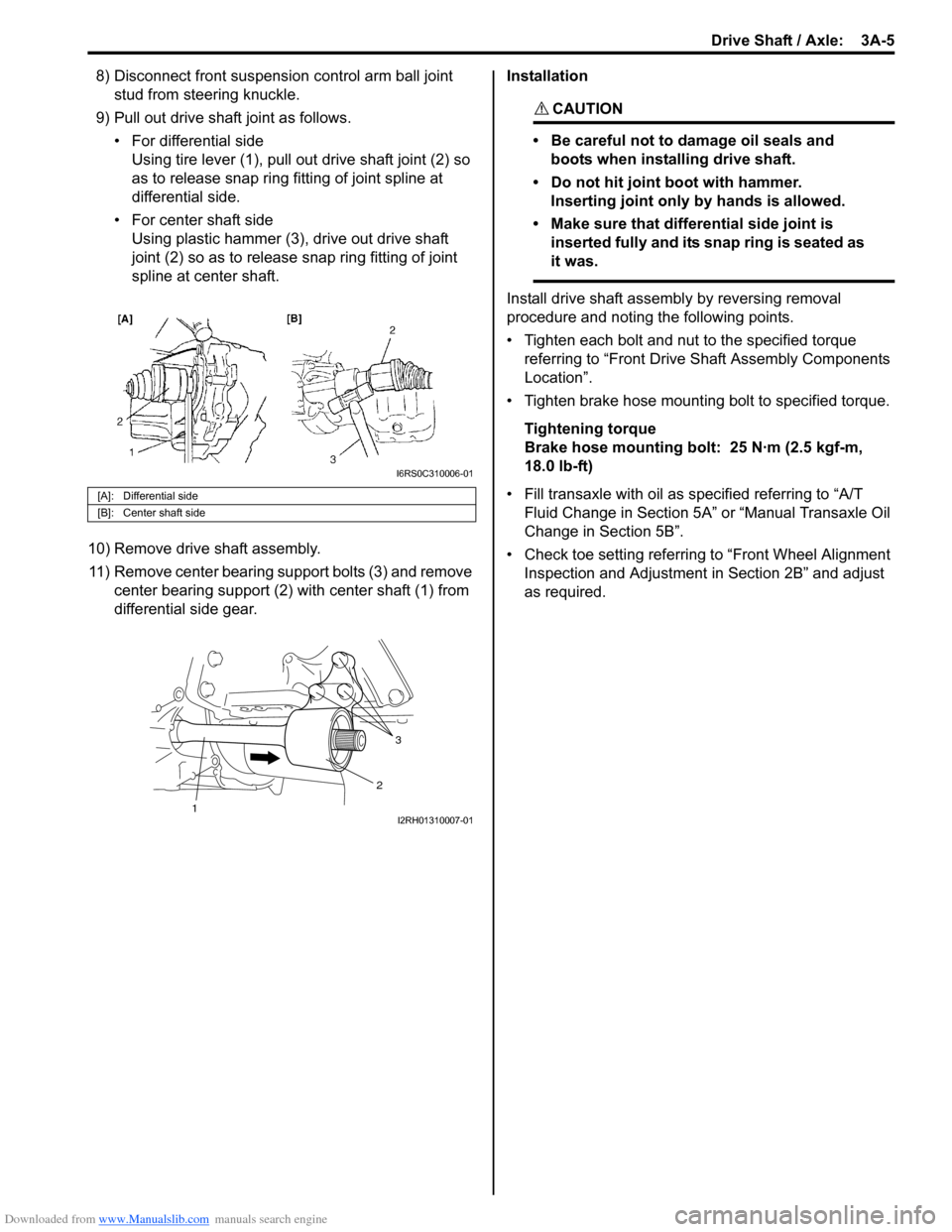
9) Pull out drive shaft joint as follows. • For differential sideUsing tire lever (1), pull out drive shaft joint (2) so
as to release snap ring fitting of joint spline at
differential side.
• For center shaft side Using plastic hammer (3), drive out drive shaft
joint (2) so as to release snap ring fitting of joint
spline at center shaft.
10) Remove drive shaft assembly. 11) Remove center bearing support bolts (3) and remove center bearing support (2) with center shaft (1) from
differential side gear. Installation
CAUTION!
• Be careful not to damage oil seals and
boots when installing drive shaft.
• Do not hit joint boot with hammer. Inserting joint only by hands is allowed.
• Make sure that differential side joint is inserted fully and its snap ring is seated as
it was.
Install drive shaft assemb ly by reversing removal
procedure and noting the following points.
• Tighten each bolt and nut to the specified torque referring to “Front Drive Shaft Assembly Components
Location”.
• Tighten brake hose mounting bolt to specified torque.
Tightening torque
Brake hose mounting bolt: 25 N·m (2.5 kgf-m,
18.0 lb-ft)
• Fill transaxle with oil as sp ecified referring to “A/T
Fluid Change in Section 5A” or “Manual Transaxle Oil
Change in Section 5B”.
• Check toe setting referring to “Front Wheel Alignment Inspection and Adjustment in Section 2B” and adjust
as required.
[A]: Differential side
[B]: Center shaft side
I6RS0C310006-01
3
2
1I2RH01310007-01
Page 496 of 1496

Downloaded from www.Manualslib.com manuals search engine 4-ii Table of Contents
Repair Instructions ..............................................4D-2Parking Brake Inspection and Adjustment ..........4D-2
Parking Brake Cable Removal and Installation ......................................................... 4D-3
Parking Brake Lever Removal and Installation ....4D-3
Specifications .... ...................................................4D-4
Tightening Torque Specifications ........................4D-4
ABS ........................................... .................4E-1
Precautions........................................................... 4E-1
Precautions in Diagnosing Troubles ................... 4E-1
Precautions in On-Vehicle Service...................... 4E-1
Precautions in Hydraulic Unit Operation Check ................................................................ 4E-1
General Description ............................................. 4E-2 ABS Description .................................................. 4E-2
ABS Hydraulic Unit / Control Module Assembly Description ....................................... 4E-2
CAN Communication System Description........... 4E-3
Schematic and Routing Diagram ........................ 4E-4 ABS Schematic ................................................... 4E-4
ABS Wiring Circuit Diagram ................................ 4E-5
Component Location ........... ................................ 4E-7
ABS Components Location ................................. 4E-7
Front Wheel Speed Sensor Components Location ............................................................ 4E-7
Rear Wheel Speed Sensor Components Location ............................................................ 4E-8
Diagnostic Information and Procedures ............ 4E-8 ABS Check .......................................................... 4E-8
ABS Warning Light Check................................. 4E-10
EBD Warning Light (Brake Warning Light) Check .............................................................. 4E-10
DTC Check........................................................ 4E-11
DTC Table ......................................................... 4E-11
DTC Clearance ................................................. 4E-12
Scan Tool Data ................................................. 4E-12
ABS Warning Light Does Not Come ON at Ignition Switch ON .......................................... 4E-13
ABS Warning Light Comes ON Steady ............. 4E-14
EBD Warning Light (Brake Warning Light) Comes ON Steady .......................................... 4E-15
Serial Data Link Circuit Check .......................... 4E-16
DTC C1021, C1022 / C1025, C1026 / C1031, C1032 / C1035, C1036: Right-Front / Left-
Front / Right-Rear / Left-Rear Wheel Speed
Sensor Circuit or Sensor Ring ........................ 4E-18
DTC C1041 / C1045 / C1051 / C1055, DTC C1042 / C1046 / C1052 / C1056: Right-Front
/ Left-Front / Right-Rear / Left-Rear Inlet
Solenoid Circuit, Right-Front / Left-Front /
Right-Rear / Left-Rear Outlet Solenoid
Circuit .............................................................. 4E-20
DTC C1057: Power Source Circuit ................... 4E-21
DTC C1061: ABS Pump Motor and/or Motor Driver Circuit ................................................... 4E-22
DTC C1063: Solenoid Valve Power Supply Driver Circuit ................................................... 4E-23
DTC C1071: ABS Control Module..................... 4E-24 DTC U1073: Control Module Communication
Bus Off ............................................................ 4E-25
DTC U1100: Lost Communication with ECM (Reception Error)............................................. 4E-27
Repair Instructions ............ ................................ 4E-28
ABS Hydraulic Unit Operati on Check................ 4E-28
ABS Hydraulic Unit / Control Module
Assembly Components ...... ............................. 4E-29
ABS Hydraulic Unit / Control Module
Assembly On-Vehicle Inspection .................... 4E-29
ABS Hydraulic Unit / Control Module
Assembly Removal and Inst allation ................ 4E-29
Front / Rear Wheel Speed Sensor On-Vehicle Inspection ........................................................ 4E-31
Front Wheel Speed Sensor Removal and Installation ....................................................... 4E-32
Front Wheel Speed Sensor Inspection ............. 4E-32
Rear Wheel Speed Sensor Removal and Installation ....................................................... 4E-33
Rear Wheel Speed Sensor Inspection .............. 4E-34
Front Wheel Encoder On-Veh icle Inspection .... 4E-34
Front wheel Enco der Removal and
Installation ....................................................... 4E-34
Rear Wheel Encoder On-Veh icle Inspection..... 4E-34
Rear Wheel Encoder Removal and Installation ....................................................... 4E-34
Specifications ..................... ................................ 4E-35
Tightening Torque Specifications ...................... 4E-35
Special Tools and Equipmen t ........................... 4E-35
Special Tool ...................................................... 4E-35
Electronic Stability Prog ram ...................4F-1
Precautions ........................................................... 4F-1
Precautions in Diagnosing Troubles ................... 4F-1
Precautions in On-Vehicle Service...................... 4F-1
Precautions in Hydraulic Unit Operation Check ................................................................ 4F-1
Precautions in Sensor Calibration ....................... 4F-1
Precautions in Speedometer Test or Other Tests ................................................................. 4F-2
General Description ............................................. 4F-2 Electronic Stability Program Description ............. 4F-2
Electronic Stability Program Construction ........... 4F-3
ESP® Hydraulic Unit / Control Module
Assembly Description........................................ 4F-5
Warning Lamp, Indicator Lamp Description ........ 4F-6
CAN Communication System Description........... 4F-6
CAN Communication System For Electronic Stability Program Description ............................ 4F-7
Schematic and Routing Diagram ........................ 4F-8 Electronic Stability Program Schematic .............. 4F-8
Electronic Stability Program Wiring Circuit Diagram............................................................. 4F-9
Component Location ............ ............................. 4F-11
Electronic Stability Program Component
Location........................................................... 4F-11
Diagnostic Information and Procedures .......... 4F-12 Electronic Stability Program System Check ...... 4F-12
ESP® Warning lamp Check .............................. 4F-14
Page 499 of 1496
Downloaded from www.Manualslib.com manuals search engine Brake Control System and Diagnosis: 4A-1
Brakes
Brake Control System and Diagnosis
Precautions
Precautions on BrakeS7RS0B4100001
Air Bag Warning
Refer to “Air Bag System Service Warning in Section 00”.
Brakes Diagnosis Note
Refer to “Brakes Diagnosis Note”.
General Description
Brakes ConstructionS7RS0B4101001
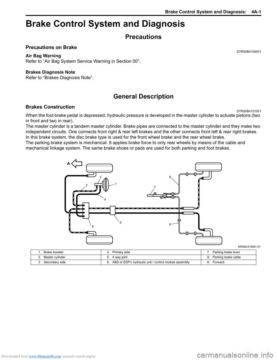
When the foot brake pedal is depressed, hydraulic pressure is developed in the master cylinder to actuate pistons (two
in front and two in rear).
The master cylinder is a tandem master cylinder. Brake pipes are connected to the master cylinder and they make two
independent circuits. One connects front right & rear left brakes and the other connects front left & rear right brakes.
In this brake system, the disc brake type is used for the front wheel brake and the rear wheel brake.
The parking brake system is mechanical. It applies brake force to only rear wheels by means of the cable and
mechanical linkage system. The same brake shoes or pads are used for both parking and foot brakes.
A
5
3
2
1
4
8
8
6
7
I6RS0C410001-01
1. Brake booster 4. Primary side 7. Parking brake lever
2. Master cylinder 5. 4 way joint 8. Parking brake cable
3. Secondary side 6. ABS or ESP® hydraulic unit / control module assembly A: Forward
Page 500 of 1496
Downloaded from www.Manualslib.com manuals search engine 4A-2 Brake Control System and Diagnosis:
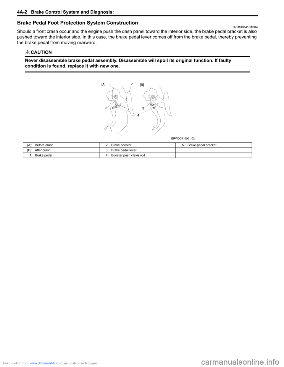
Brake Pedal Foot Protection System ConstructionS7RS0B4101004
Should a front crash occur and the engine push the dash panel toward the interior side, the brake pedal bracket is also
pushed toward the interior side. In this case, the brake pedal lever comes off from the brake pedal, thereby preventing
the brake pedal from moving rearward.
CAUTION!
Never disassemble brake pedal assembly. Disassemble will spoil its original function. If faulty
condition is found, replace it with new one.
[A]: Before crash2. Brake booster5. Brake pedal bracket
[B]: After crash 3. Brake pedal lever
1. Brake pedal 4. Booster push clevis rod
I6RW0C410001-02
Page 525 of 1496
Downloaded from www.Manualslib.com manuals search engine Rear Brakes: 4C-1
Brakes
Rear Brakes
Repair Instructions
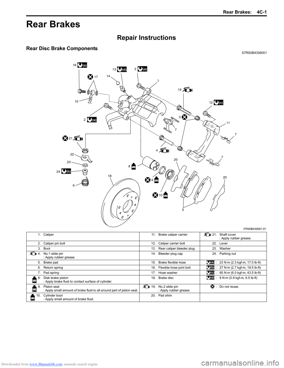
Rear Disc Brake ComponentsS7RS0B4306001
(d)
(c)
(a)
(a)
(a)16171413
2
1
15 2 19
12
117
7
3
7
4
20 20
5
10
9
8
(b)
18
6
24
23
22
21
I7RS0B430001-01
1. Caliper
11. Brake caliper carrier21. Shaft cover
: Apply rubber grease.
2. Caliper pin bolt 12. Caliper carrier bolt22. Lever
3. Boot 13. Rear caliper bleeder plug23. Washer
4. No.1 slide pin : Apply rubber grease. 14. Bleeder plug cap
24. Parking nut
5. Brake pad 15. Brake flexible hose: 23 N⋅m (2.3 kgf-m, 17.0 lb-ft)
6. Return spring 16. Flexible hose joint bolt: 27 N⋅m (2.7 kgf-m, 19.5 lb-ft)
7. Pad spring 17. Hose washer: 60 N⋅m (6.0 kgf-m, 43.5 lb-ft)
8. Disk brake piston : Apply brake fluid to contact surface of cylinder. 18. Brake disc
: 9 N⋅m (0.9 kgf-m, 6.5 lb-ft)
9. Piston seal : Apply small amount of brake fluid to all around part of piston seal. 19. No.2 slide pin
: Apply rubber grease. : Do not reuse.
10. Cylinder boot : Apply small amount of brake fluid. 20. Pad shim