2006 SUZUKI SWIFT Fuel temperature sensor
[x] Cancel search: Fuel temperature sensorPage 179 of 1496
Downloaded from www.Manualslib.com manuals search engine Engine General Information and Diagnosis: 1A-129
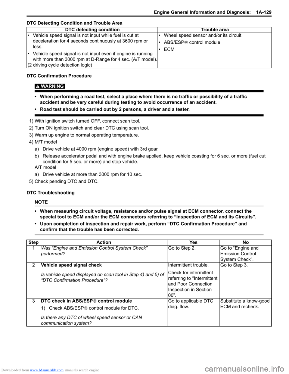
DTC Detecting Condition and Trouble Area
DTC Confirmation Procedure
WARNING!
• When performing a road test, select a place where there is no traffic or possibility of a traffic accident and be very careful during testing to avoid occurrence of an accident.
• Road test should be carried out by 2 persons, a driver and a tester.
1) With ignition switch turned OFF, connect scan tool.
2) Turn ON ignition switch and clear DTC using scan tool.
3) Warm up engine to normal operating temperature.
4) M/T model
a) Drive vehicle at 4000 rpm (e ngine speed) with 3rd gear.
b) Release accelerator pedal and with engine brake applied, keep vehicle coasting for 6 sec. or more (fuel cut condition for 5 sec. or more) and stop vehicle.
A/T model
a) Drive vehicle at more than 3000 rpm for 10 sec.
5) Check pending DTC and DTC.
DTC Troubleshooting
NOTE
• When measuring circuit voltage, resistance and/ or pulse signal at ECM connector, connect the
special tool to ECM and/or the ECM connectors re ferring to “Inspection of ECM and Its Circuits”.
• Upon completion of inspection and repair work, perform “DTC Confirmation Procedure” and confirm that the trouble has been corrected.
DTC detecting condition Trouble area
• Vehicle speed signal is not input while fuel is cut at deceleration for 4 seconds continuously at 3600 rpm or
less.
• Vehicle speed signal is not input even if engine is running with more than 3000 rpm at D-Range for 4 sec. (A/T model).
(2 driving cycle detection logic) • Wheel speed sensor and/or its circuit
• ABS/ESP®
control module
•ECM
Step Action YesNo
1 Was “Engine and Emission Control System Check”
performed? Go to Step 2.
Go to “Engine and
Emission Control
System Check”.
2 Vehicle speed signal check
Is vehicle speed displayed on scan tool in Step 4) and 5) of
“DTC Confirmation Procedure”? Intermittent trouble.
Check for intermittent
referring to “Intermittent
and Poor Connection
Inspection in Section
00”.Go to Step 3.
3 DTC check in ABS/ESP ® control module
1) Check ABS/ESP ® control module for DTC.
Is there any DTC of wheel speed sensor or CAN
communication system? Go to applicable DTC
diag. flow.
Substitute a know-good
ECM and recheck.
Page 234 of 1496
Downloaded from www.Manualslib.com manuals search engine 1A-184 Engine General Information and Diagnosis:
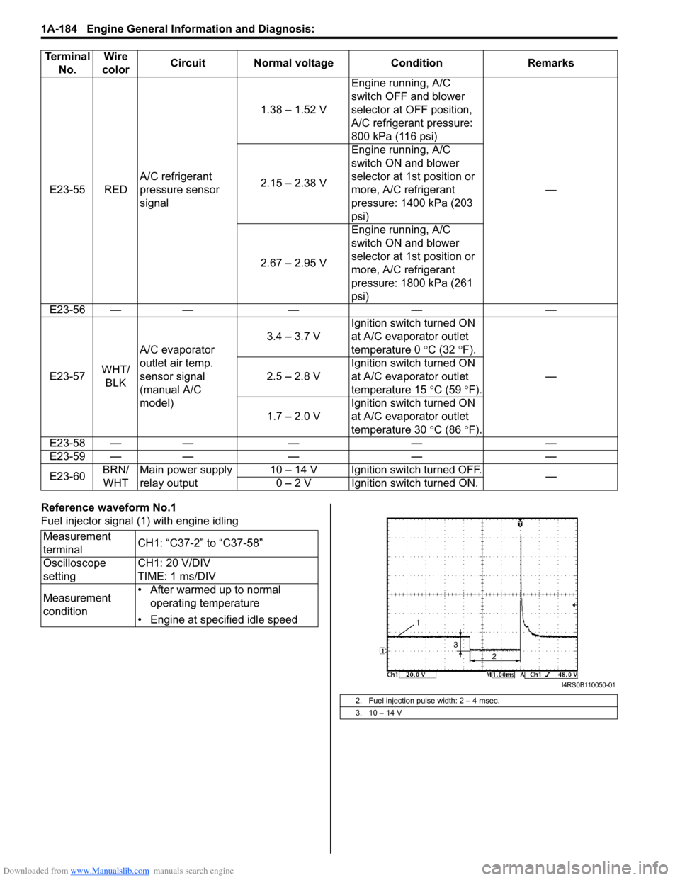
Reference waveform No.1
Fuel injector signal (1) with engine idling
E23-55 RED
A/C refrigerant
pressure sensor
signal 1.38 – 1.52 V
Engine running, A/C
switch OFF and blower
selector at OFF position,
A/C refrigerant pressure:
800 kPa (116 psi)
—
2.15 – 2.38 V Engine running, A/C
switch ON and blower
selector at 1st position or
more, A/C refrigerant
pressure: 1400 kPa (203
psi)
2.67 – 2.95 V Engine running, A/C
switch ON and blower
selector at 1st position or
more, A/C refrigerant
pressure: 1800 kPa (261
psi)
E23-56 — — — — —
E23-57 WHT/
BLK A/C evaporator
outlet air temp.
sensor signal
(manual A/C
model) 3.4 – 3.7 V
Ignition switch turned ON
at A/C evaporator outlet
temperature 0
°C (32 °F).
—
2.5 – 2.8 V Ignition switch turned ON
at A/C evaporator outlet
temperature 15
°C (59 °F).
1.7 – 2.0 V Ignition switch turned ON
at A/C evaporator outlet
temperature 30
°C (86 °F).
E23-58 — — — — —
E23-59 — — — — —
E23-60 BRN/
WHT Main power supply
relay output 10 – 14 V Ignition switch turned OFF.
—
0 – 2 V Ignition switch turned ON.
Terminal
No. Wire
color Circuit Normal voltage Condition Remarks
Measurement
terminal CH1: “C37-2” to “C37-58”
Oscilloscope
setting CH1: 20 V/DIV
TIME: 1 ms/DIV
Measurement
condition • After warmed up to normal
operating temperature
• Engine at specified idle speed
2. Fuel injection pulse width: 2 – 4 msec.
3. 10 – 14 V
I4RS0B110050-01
Page 238 of 1496
Downloaded from www.Manualslib.com manuals search engine 1A-188 Engine General Information and Diagnosis:
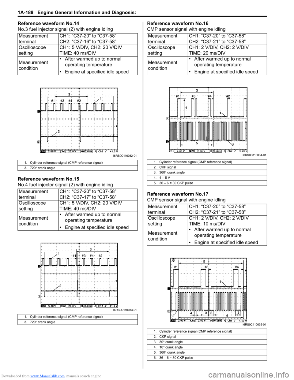
Reference waveform No.14
No.3 fuel injector signal (2) with engine idling
Reference waveform No.15
No.4 fuel injector sig nal (2) with engine idling Reference waveform No.16
CMP sensor signal with engine idling
Reference waveform No.17
CMP sensor signal with engine idling
Measurement
terminal
CH1: “C37-20” to “C37-58”
CH2: “C37-16” to “C37-58”
Oscilloscope
setting CH1: 5 V/DIV, CH2: 20 V/DIV
TIME: 40 ms/DIV
Measurement
condition • After warmed up to normal
operating temperature
• Engine at specified idle speed
1. Cylinder reference signal (CMP reference signal)
3. 720 ° crank angle
Measurement
terminal CH1: “C37-20” to “C37-58”
CH2: “C37-17” to “C37-58”
Oscilloscope
setting CH1: 5 V/DIV, CH2: 20 V/DIV
TIME: 40 ms/DIV
Measurement
condition • After warmed up to normal
operating temperature
• Engine at specified idle speed
1. Cylinder reference signal (CMP reference signal)
3. 720 ° crank angle
I6RS0C110032-01
I6RS0C110033-01
Measurement
terminal CH1: “C37-20” to “C37-58”
CH2: “C37-21” to “C37-58”
Oscilloscope
setting CH1: 2 V/DIV, CH2: 2 V/DIV
TIME: 20 ms/DIV
Measurement
condition • After warmed up to normal
operating temperature
• Engine at specified idle speed
1. Cylinder reference signal (CMP reference signal)
2. CKP signal
3. 360 ° crank angle
4. 4 – 5 V
5. 36 – 6 = 30 CKP pulse
Measurement
terminal CH1: “C37-20” to “C37-58”
CH2: “C37-21” to “C37-58”
Oscilloscope
setting CH1: 2 V/DIV, CH2: 2 V/DIV
TIME: 10 ms/DIV
Measurement
condition • After warmed up to normal
operating temperature
• Engine at specified idle speed
1. Cylinder reference signal (CMP reference signal)
2. CKP signal
3. 30 ° crank angle
4. 10 ° crank angle
5. 360 ° crank angle
6. 36 – 6 = 30 CKP pulse
I6RS0C110034-01
I6RS0C110035-01
Page 240 of 1496
Downloaded from www.Manualslib.com manuals search engine 1A-190 Engine General Information and Diagnosis:
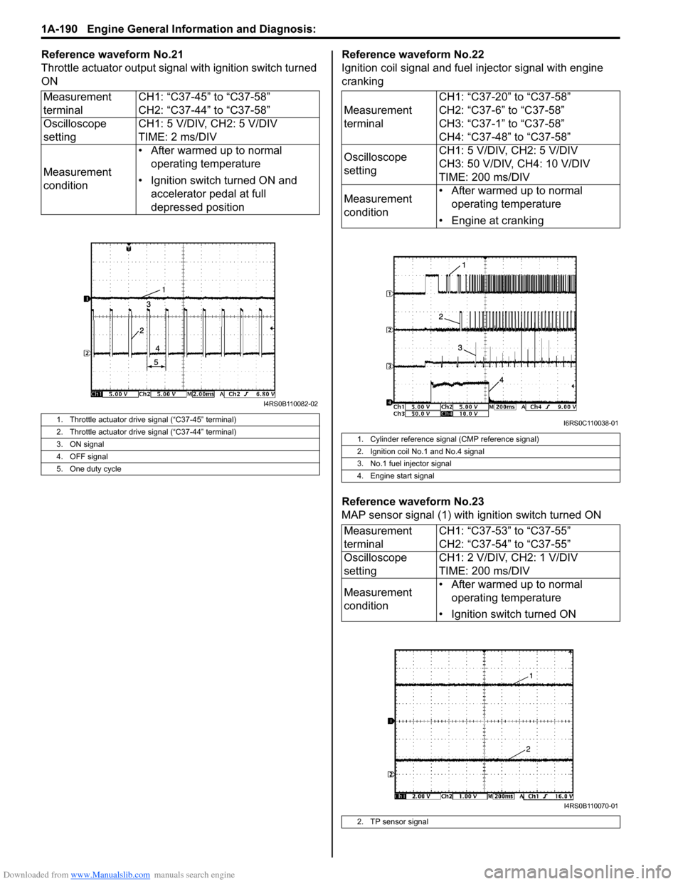
Reference waveform No.21
Throttle actuator output signal with ignition switch turned
ONReference waveform No.22
Ignition coil signal and fuel injector signal with engine
cranking
Reference waveform No.23
MAP sensor signal (1) with ignition switch turned ON
Measurement
terminal
CH1: “C37-45” to “C37-58”
CH2: “C37-44” to “C37-58”
Oscilloscope
setting CH1: 5 V/DIV, CH2: 5 V/DIV
TIME: 2 ms/DIV
Measurement
condition • After warmed up to normal
operating temperature
• Ignition switch turned ON and accelerator pedal at full
depressed position
1. Throttle actuator drive signal (“C37-45” terminal)
2. Throttle actuator drive signal (“C37-44” terminal)
3. ON signal
4. OFF signal
5. One duty cycle
I4RS0B110082-02
Measurement
terminal CH1: “C37-20” to “C37-58”
CH2: “C37-6” to “C37-58”
CH3: “C37-1” to “C37-58”
CH4: “C37-48” to “C37-58”
Oscilloscope
setting CH1: 5 V/DIV, CH2: 5 V/DIV
CH3: 50 V/DIV, CH4: 10 V/DIV
TIME: 200 ms/DIV
Measurement
condition • After warmed up to normal
operating temperature
• Engine at cranking
1. Cylinder reference signal (CMP reference signal)
2. Ignition coil No.1 and No.4 signal
3. No.1 fuel injector signal
4. Engine start signal
Measurement
terminal CH1: “C37-53” to “C37-55”
CH2: “C37-54” to “C37-55”
Oscilloscope
setting CH1: 2 V/DIV, CH2: 1 V/DIV
TIME: 200 ms/DIV
Measurement
condition • After warmed up to normal
operating temperature
• Ignition switch turned ON
2. TP sensor signal
I6RS0C110038-01
I4RS0B110070-01
Page 669 of 1496
Downloaded from www.Manualslib.com manuals search engine Automatic Transmission/Transaxle: 5A-25
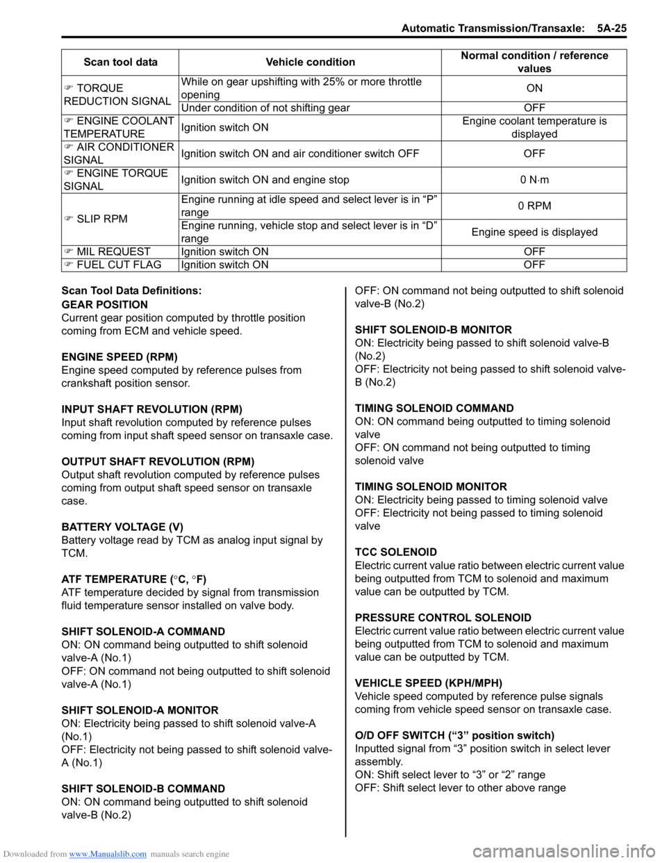
Scan Tool Data Definitions:
GEAR POSITION
Current gear position computed by throttle position
coming from ECM and vehicle speed.
ENGINE SPEED (RPM)
Engine speed computed by reference pulses from
crankshaft position sensor.
INPUT SHAFT REVOLUTION (RPM)
Input shaft revolution computed by reference pulses
coming from input shaft speed sensor on transaxle case.
OUTPUT SHAFT REVOLUTION (RPM)
Output shaft revolution computed by reference pulses
coming from output shaft speed sensor on transaxle
case.
BATTERY VOLTAGE (V)
Battery voltage read by TCM as analog input signal by
TCM.
ATF TEMPERATURE (°C, °F)
ATF temperature decided by signal from transmission
fluid temperature sensor installed on valve body.
SHIFT SOLENOID-A COMMAND
ON: ON command being outputted to shift solenoid
valve-A (No.1)
OFF: ON command not being outputted to shift solenoid
valve-A (No.1)
SHIFT SOLENOID-A MONITOR
ON: Electricity being passed to shift solenoid valve-A
(No.1)
OFF: Electricity not being passed to shift solenoid valve-
A (No.1)
SHIFT SOLENOID-B COMMAND
ON: ON command being outputted to shift solenoid
valve-B (No.2) OFF: ON command not being outputted to shift solenoid
valve-B (No.2)
SHIFT SOLENOID-B MONITOR
ON: Electricity being passed to shift solenoid valve-B
(No.2)
OFF: Electricity not being passed to shift solenoid valve-
B (No.2)
TIMING SOLENOID COMMAND
ON: ON command being outputted to timing solenoid
valve
OFF: ON command not being outputted to timing
solenoid valve
TIMING SOLENOID MONITOR
ON: Electricity being passed to timing solenoid valve
OFF: Electricity not being passed to timing solenoid
valve
TCC SOLENOID
Electric current value ratio between electric current value
being outputted from TCM to solenoid and maximum
value can be outputted by TCM.
PRESSURE CONTROL SOLENOID
Electric current value ratio between electric current value
being outputted from TCM to solenoid and maximum
value can be outputted by TCM.
VEHICLE SPEED (KPH/MPH)
Vehicle speed computed by reference pulse signals
coming from vehicle speed sensor on transaxle case.
O/D OFF SWITCH (“3” position switch)
Inputted signal from “3” position switch in select lever
assembly.
ON: Shift select lever to “3” or “2” range
OFF: Shift select lever to other above range
�)
TORQUE
REDUCTION SIGNAL While on gear upshifting with 25% or more throttle
opening
ON
Under condition of not shifting gear OFF
�) ENGINE COOLANT
TEMPERATURE Ignition switch ON Engine coolant temperature is
displayed
�) AIR CONDITIONER
SIGNAL Ignition switch ON and air conditioner switch OFF OFF
�) ENGINE TORQUE
SIGNAL Ignition switch ON and engine stop 0 N
⋅m
�) SLIP RPM Engine running at idle speed
and select lever is in “P”
range 0 RPM
Engine running, vehicle stop and select lever is in “D”
range Engine speed is displayed
�) MIL REQUEST Ignition switch ON OFF
�) FUEL CUT FLAG Ignition switch ON OFFScan tool data Vehicle condition
Normal condition / reference
values
Page 670 of 1496
Downloaded from www.Manualslib.com manuals search engine 5A-26 Automatic Transmission/Transaxle:
TRANSAXLE RANGE
Transaxle range detected by signal fed from
transmission range sensor.
D RANGE SIGNAL
ON: Signal which TCM require ECM to increase idle
speed
OFF: Signal which TCM does not require ECM to
increase idle speed
THROTTLE POSITION (%)
Throttle opening ratio computed by CAN signal from
ECM.
BRAKE SWITCH
Inputted signal from brake light switch on pedal bracket.
ON: Brake pedal depressed
OFF: Brake pedal released
TORQUE REDUCTION SIGNAL
ON: Signal which TCM require ECM to reduce output
torque at shifting gear
OFF: Signal which TCM does not require ECM to reduce
output torque
ENGINE COOLANT TEMPERATURE ( °C, °F)
Engine coolant temperature computed by CAN signal
from ECM. AIR CONDITIONER SIGNAL
ON: Signal which inform that air conditioner compressor
is turned ON.
OFF: Signal which inform that air conditioner
compressor is not turned ON.
ENGINE TORQUE SIGNAL (N
⋅m)
Engine torque computed by duty pulse signal outputted
from ECM.
SLIP RPM (RPM)
This parameter indicates slip ping rotation in the torque
converter (difference between input shaft rotation and
engine rotation)
MIL REQUEST
ON: Signal which TCM requires combination meter to
turn on malfunction indicator lamp.
OFF: Signal which TCM does not require combination
meter to turn on malf unction indicator lamp.
FUEL CUT FLAG
ON: Signal which inform that fuel cut is operating.
OFF: Signal which inform that fuel cut is not operating.
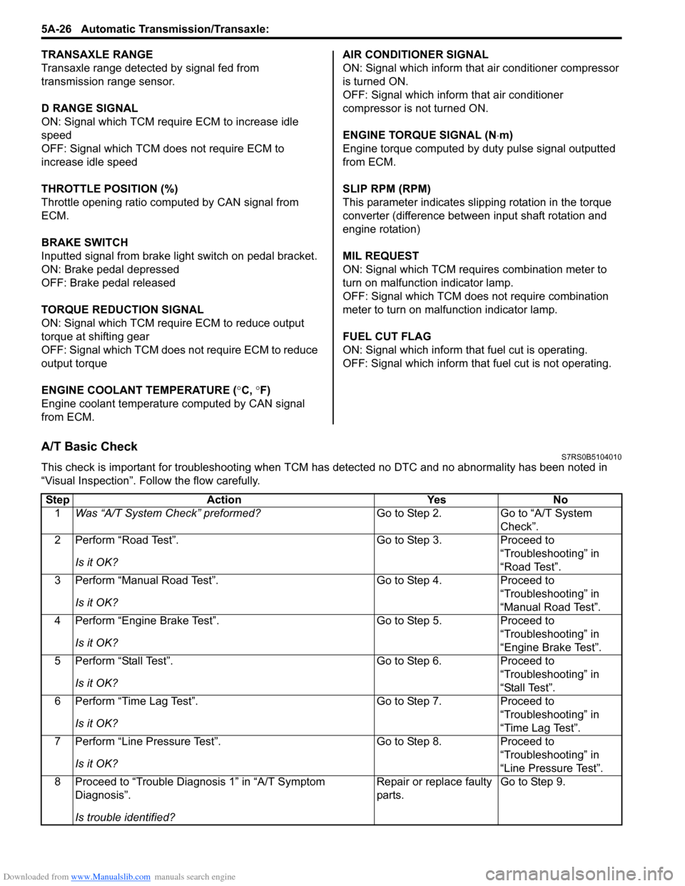
A/T Basic CheckS7RS0B5104010
This check is important for troubleshooting when TCM has detected no DTC and no abnormality has been noted in
“Visual Inspection”. Fo llow the flow carefully.
Step Action YesNo
1 Was “A/T System Check” preformed? Go to Step 2.Go to “A/T System
Check”.
2 Perform “Road Test”.
Is it OK? Go to Step 3.
Proceed to
“Troubleshooting” in
“Road Test”.
3 Perform “Manual Road Test”.
Is it OK? Go to Step 4.
Proceed to
“Troubleshooting” in
“Manual Road Test”.
4 Perform “Engine Brake Test”.
Is it OK? Go to Step 5.
Proceed to
“Troubleshooting” in
“Engine Brake Test”.
5 Perform “Stall Test”.
Is it OK? Go to Step 6.
Proceed to
“Troubleshooting” in
“Stall Test”.
6 Perform “Time Lag Test”.
Is it OK? Go to Step 7.
Proceed to
“Troubleshooting” in
“Time Lag Test”.
7 Perform “Line Pressure Test”.
Is it OK? Go to Step 8.
Proceed to
“Troubleshooting” in
“Line Pressure Test”.
8 Proceed to “Trouble Diag nosis 1” in “A/T Symptom
Diagnosis”.
Is trouble identified? Repair or replace faulty
parts.
Go to Step 9.
Page 1168 of 1496

Downloaded from www.Manualslib.com manuals search engine 9-ii Table of Contents
List of Connectors ........................................... 9A-103
C Connector .................................................... 9A-103
D Connector (M16A engine) ........................... 9A-104
E Connector .................................................... 9A-104
G Connector .................................................... 9A-106
J Connector ..................................................... 9A-108
K Connector .................................................... 9A-109
L Connector..................................................... 9A-109
M Connector (SPORT model) ......................... 9A-111
O Connector .................................................... 9A-111
R Connector .................................................... 9A-111
Lighting Systems .................................... 9B-1
Component Location ........... ................................9B-1
Lighting System Component s Location............... 9B-1
Interior Light System Location............................. 9B-2
Diagnostic Information and Procedures ............ 9B-2 Headlight Symptom Diagnosis ............................ 9B-2
Headlight Leveling System Symptom Diagnosis (If Equipped) ..................................... 9B-2
Turn Signal and Hazard Warning Light Symptom Diagnosis .......................................... 9B-3
Clearance, Tail and License Plate Light Symptom Diagnosis .......................................... 9B-3
Back-Up Light Symptom Diagnosis..................... 9B-4
Brake Light Symptom Diagnosis ......................... 9B-4
Front Fog Light Symptom Diagnosis (If Equipped) .......................................................... 9B-4
Interior Light Symptom Diagnosis ....................... 9B-5
Repair Instructions ..............................................9B-5 Headlight Housing Removal and Installation ...... 9B-5
Headlight Bulb Replacemen t............................... 9B-6
Headlight Aiming Adjustment with Screen .......... 9B-6
Headlight Switch (in Lighting Switch) Removal and Installation ................................... 9B-8
Headlight Switch (in Lighting Switch) Inspection .......................................................... 9B-8
Hazard Warning Switch Removal and Installation ......................................................... 9B-8
Hazard Warning Switch Inspection ..................... 9B-9
Brake Light Switch Inspection ............................. 9B-9
Turn Signal Light Switch (in Lighting Switch) Removal and Installation ................................... 9B-9
Turn Signal Light Switch (in Lighting Switch) Inspection .......................................................... 9B-9
Turn Signal and Hazard Warning Relay Removal and Installation ................................... 9B-9
Turn Signal and Hazard Warning Relay Inspection ........................................................ 9B-10
License Light Removal and Installation............. 9B-10
Front Fog Light Removal and Installation (If Equipped) ........................................................ 9B-11
Front Fog Light Bulb Replacement (If Equipped) ........................................................ 9B-11
Front Fog Light Switch Inspection (If Equipped) ........................................................ 9B-11
Front Fog Light Relay Inspection (If Equipped) ........................................................ 9B-11
Front Fog Light Aiming Adjustment with Screen (If Equipped) ....................................... 9B-12 Headlight Leveling Switch Inspection (If
Equipped) ........................................................ 9B-13
Headlight Leveling Actuator Inspection (If Equipped) ........................................................ 9B-13
Instrumentation / Driver Info. / Horn ...... 9C-1
Precautions ...........................................................9C-1 Precautions in Diagnosing Troubles for Combination Meter ............................................9C-1
General Description .............................................9C-1 CAN Communication System Description...........9C-1
Auto Volume Co ntrol System Description (If
Equipped) ..........................................................9C-3
Schematic and Routing Diagram ........................9C-4 Combination Meter Circuit Diagram ....................9C-4
Component Location ............ ...............................9C-6
Audio System Component Location ....................9C-6
Diagnostic Information and Procedures ............9C-6 Speedometer and VSS Symp tom Diagnosis ......9C-6
Tachometer Symptom Diagnosis ........................9C-6
Engine Coolant Temperature (ECT) Meter Symptom Diagnosis ..........................................9C-7
Fuel Meter Symptom Diagnosis ..........................9C-7
Low Fuel Warning Light Symptom Diagnosis .....9C-7
Oil Pressure Warning Light Symptom Diagnosis ..........................................................9C-8
Brake and Parking Brake Warning Light Symptom Diagnosis ..........................................9C-8
Seat Belt Reminder Light Symptom Diagnosis (If Equipped)......................................................9C-8
A/T Shift Position Indicator Symptom Diagnosis (A/T Model).......................................9C-9
Charge Warning Light Sy mptom Diagnosis ........9C-9
Main Beam (High Beam) Indicator Symptom Diagnosis ..........................................................9C-9
Warning Buzzer Circuit Sy mptom Diagnosis ....9C-10
Cigarette Lighter Symptom Diagnosis (If Equipped) ........................................................9C-10
Horn Symptom Diagnosis .................................9C-10
Information Display Symptom Diagnosis (If Equipped) ........................................................9C-11
Clock Symptom Diagnosis (If Equipped)...........9C-12
Audio System Symptom Diagnosis (If Equipped) ........................................................9C-12
Remote Audio Control Switch Symptom Diagnosis (If Equipped) ...................................9C-13
Navigation Symptom Diagnosis (If Equipped)...9C-14
Repair Instructions ............ ................................9C-14
Ignition Switch Removal and Installation...........9C-14
Ignition Switch Inspection..................................9C-14
Combination Meter Removal and Installation ...9C-15
Fuel Level Sensor Removal and Installation .....9C-15
Fuel Level Sensor Inspection ............................9C-15
Oil Pressure Switch Remova l and Installation ..9C-15
Oil Pressure Switch Inspec tion .........................9C-16
Engine Coolant Temperature (ECT) Sensor Inspection ........................................................9C-16
Brake Fluid Level Switch Inspection .................9C-16
Parking Brake Switch Inspec tion.......................9C-16
Page 1185 of 1496

Downloaded from www.Manualslib.com manuals search engine Wiring Systems: 9A-14
E: Main harness (RHD)
E: Main harness
56
E06E12
E03or
E85
E07
E09
E08
E13
E10
E11E05 E04
E01 E02
E19
7
22
E34E31
E32
E57
E24
(TO C36)
E33
E36
E35
E30
E29
E28
E20
E21
E22
E27
E26
E23
E25E17E56
E18
E14 E15
E55
E
I7RS0B910902-02
No./Color
Connective position No./ColorConnective position
E01/GRY Windshield wiper motor E22/N Front position light (L)
E02/GRY Brake fluid level switch E23/GRY ECM
E03/BLK ABS control module E24/N Engine Harness (To C36)
E04/BLK A/C pressure sensor E25/BLK Wheel speed sensor (FL)
E05/BLK Wheel speed sensor (FR) E26/N Main fuse box
E06/N Side turn signal light (R) E27/BLK Main fuse box
E07/N Front position light (R) E28/BLK Radiator fan relay #1
E08/BLK Head light (R) E29/BLK Radiator fan relay #2
E09/GRY Front turn signal light (R) E30/BLK Radiator fan relay #3
E10/GRN Rear washer motor E31/BLK Starting motor relay
E11/BLU Windshield washer motor E32/BLK Main relay
E12/BLK (IF EQPD) Front fog light (R)
E33/BLK A/T relay
E13/YEL Forward sensor E34/BLK (IF
EQPD) Front fog light relay
E14/BLK Outside air temperature sensor E35/BLK Fuel pump relay
E15/BLK Horn E36/BLK A/C compressor relay
E17/BLK Radiator fan motor E55/- Weld splice
E18/BLK (IF EQPD) Front fog light (L) E56/BLK
(M16A
engine) Throttle actuator control relay
E19/N Side turn signal light (L) E57/BLK Diagnosis connector #1
E20/GRY Front turn signal light (L) E85/BLK (IF
EQPD) ESP
® control module
E21/BLK Headlight (R)