2006 SUZUKI SWIFT D-5
[x] Cancel search: D-5Page 1169 of 1496

Downloaded from www.Manualslib.com manuals search engine Table of Contents 9-iii
Door Switch (Front / Rear Door) Inspection ...... 9C-17
Rear End Door Switch Inspection ..................... 9C-17
Outside Air Temperature Sensor Removal and Installation (If Equipped) .......................... 9C-17
Outside Air Temperature Sensor Inspection (If Equipped) ................................................... 9C-17
Instrument Panel Removal and Installation....... 9C-18
Information Display (Clock) Removal and Installation ....................................................... 9C-19
Audio Unit Removal and In stallation ................. 9C-19
Front Speaker Removal and Installation ........... 9C-19
Rear Speaker Removal and Installation............ 9C-20
Horn Removal and Installation .......................... 9C-20
Horn Inspection ................................................. 9C-20
Horn Relay Inspection ....................................... 9C-20
Antenna Amplifier Removal and Installation ..... 9C-21
Remote Audio Control Switch Removal and Installation (If Equipped) ................................. 9C-21
Remote Audio Control Switch Inspection (If Equipped)........................................................ 9C-22
Vehicle Speed Signal Inspection (For Audio Unit) (If Equipped) ........................................... 9C-22
Specifications ..................................................... 9C-22
Tightening Torque Specifications ...................... 9C-22
Wipers / Washers............ ......................... 9D-1
Diagnostic Information and Procedures ............ 9D-1
Front Wiper and Washer Symptom Diagnosis .... 9D-1
Rear Wiper and Washer Symptom Diagnosis..... 9D-1
Repair Instructions .............................................. 9D-2 Wipers and Washers Components ..................... 9D-2
Washer Tank and Washer Pump Removal and Installation .................................................. 9D-3
Washer Pump Inspection .................................... 9D-3
Windshield Wiper Removal and Installation ........ 9D-4
Windshield Wiper Motor Inspection..................... 9D-5
Rear Wiper Removal and Installation.................. 9D-6
Rear Wiper Motor Inspection .............................. 9D-7
Windshield Wiper and Washer Switch Removal and Installation................................... 9D-7
Windshield Wiper and Washer Switch Inspection.......................................................... 9D-8
Rear Wiper and Washer Switch Removal and Installation ......................................................... 9D-9
Rear Wiper and Washer Switch Inspection......... 9D-9
Rear Wiper Relay Removal and Installation ..... 9D-10
Rear Wiper Relay Inspection ............................ 9D-10
Specifications ..................................................... 9D-10
Tightening Torque Specifications ...................... 9D-10
Glass / Windows / Mirrors.. ..................... 9E-1
General Description ............................................. 9E-1
Rear End Door Window Defogger System Description ........................................................ 9E-1
Windshield Construction ..................................... 9E-1
Diagnostic Information and Procedures ............ 9E-2 Rear End door Window Defogger Symptom Diagnosis .......................................................... 9E-2 Power Window Control System Symptom
Diagnosis .......................................................... 9E-2
Power Door Mirror Control System Symptom Diagnosis .......................................................... 9E-3
Door Mirror Heater Symptom Diagnosis (If
Equipped) .......................................................... 9E-3
Repair Instructions ........... ................................... 9E-4
Windshield Removal and In stallation .................. 9E-4
Front Door Window Components ........................ 9E-8
Front Door Glass Removal and Installation ........ 9E-8
Front Door Window Re gulator Removal and
Installation ......................................................... 9E-9
Front Door Window Regula tor Inspection ......... 9E-10
Rear Door Window Components ...................... 9E-10
Rear Door Glass Removal and Installation ....... 9E-11
Rear Door Window Regulator Removal and Installation ....................................................... 9E-12
Rear Door Window Regulato r Inspection .......... 9E-12
Rear End Door Window Components ............... 9E-13
Rear End Door Glass Removal and Installation ....................................................... 9E-13
Rear End Door Window Defogger Switch Inspection ........................................................ 9E-14
Rear End Door Window Defogger Relay Inspection ........................................................ 9E-14
Rear End Door Window Defogger Wire Inspection ........................................................ 9E-15
Rear End Door Window Defogger Wire
Repair.............................................................. 9E-15
Power Window Main Switch Inspection ............ 9E-16
Power Window Sub Switch Inspection .............. 9E-17
Door Mirror Components.. ................................. 9E-18
Door Mirror Removal and In stallation................ 9E-18
Power Door Mirror Switch Inspection ................ 9E-18
Power Door Mirror Actuator Inspection ............. 9E-19
Door Mirror Heater Switch Inspection (If Equipped) ........................................................ 9E-19
Door Mirror Heater Inspec tion (If Equipped) ..... 9E-19
Special Tools and Equipmen t ........................... 9E-19
Recommended Service Material ....................... 9E-19
Security and Locks......... ..........................9F-1
General Description ............................................. 9F-1
Key Coding Construction .................................... 9F-1
Rear End Door Opener System Description ....... 9F-1
Component Location ............ ............................... 9F-2
Power Door Lock and Keyless Entry System
Component Location ......................................... 9F-2
Diagnostic Information and Procedures ............ 9F-3 Power Door Lock System Symptom Diagnosis .......................................................... 9F-3
Power Door Lock System Operation Inspection .......................................................... 9F-3
Keyless Entry System Symptom Diagnosis (If
Equipped) .......................................................... 9F-4
Keyless Entry System Operation Inspection ....... 9F-5
Door Lock Function of Keyless Start System Symptom Diagnosis (If Equipped)..................... 9F-5
Page 1216 of 1496

Downloaded from www.Manualslib.com manuals search engine 9A-45 Wiring Systems:
System Circuit Diagram
System Circuit DiagramS7RS0B910E001
Refer to “A-1 Cranking System Circuit Diagram”.
Refer to “A-2 Charging System Circuit Diagram”.
Refer to “A-3 Ignition System Circuit Diagram”.
Refer to “A-4 Cooling System Circuit Diagram”.
Refer to “A-5 Engine and A/C Control System Circuit Diagram”.
Refer to “A-6 A/T Control System Circuit Diagram”.
Refer to “A-7 Immobilizer System Circuit Diagram”.
Refer to “A-8 Body Control System Circuit Diagram”.
Refer to “B-1 Windshield Wiper and Washer Circuit Diagram”.
Refer to “B-2 Rear Wiper and Washer Circuit Diagram”.
Refer to “B-3 Rear Defogger Circuit Diagram”.
Refer to “B-4 Power Window Circuit Diagram”.
Refer to “B-5 Power Door Lock Circuit Diagram”.
Refer to “B-6 Power Mi rror Circuit Diagram”.
Refer to “B-7 Horn Circuit Diagram”.
Refer to “B-8 Seat Heater Circuit Diagram”.
Refer to “B-9 Keyless Star t System Circuit Diagram”.
Refer to “C-1 Combination Me ter Circuit Diagram (Meter)”.
Refer to “C-2 Combination Mete r Circuit Diagram (Indicator)”.
Refer to “C-3 Combination Meter Circuit Diagram (Warning Light)”.
Refer to “D-1 Headlight System Circuit Diagram”.
Refer to “D-2 Position, Tail and Licence Plate Light System Circuit Diagram”.
Refer to “D-3 Front Fog Light System Circuit Diagram”.
Refer to “D-4 Illumination Light System Circuit Diagram”.
Refer to “D-5 Interior Li ght System Circuit Diagram”.
Refer to “D-6 Turn Signal and Hazard Warning Light System Circuit Diagram”.
Refer to “D-7 Brake Light System Circuit Diagram”.
Refer to “D-8 Back-Up Light System Circuit Diagram”.
Refer to “D-9 Headlight Beam Leveling System Circuit Diagram”.
Refer to “D-10 Rear Fog Light Circuit Diagram”.
Refer to “E-1 Heater System Circuit Diagram”.
Refer to “E-2 Auto A/C System Circuit Diagram”.
Refer to “F-1 Air-Bag System Circuit Diagram”.
Refer to “F-2 Anti-Lock Brake System Circuit Diagram”.
Refer to “F-3 Electronic Stabilit y Program System Circuit Diagram”.
Refer to “F-4 Power Steeri ng System Circuit Diagram”.
Refer to “G-1 Audio Sy stem Circuit Diagram”.
Refer to “G-2 Multi Information Display / Accessory Socket System Circuit Diagram”.
Page 1230 of 1496

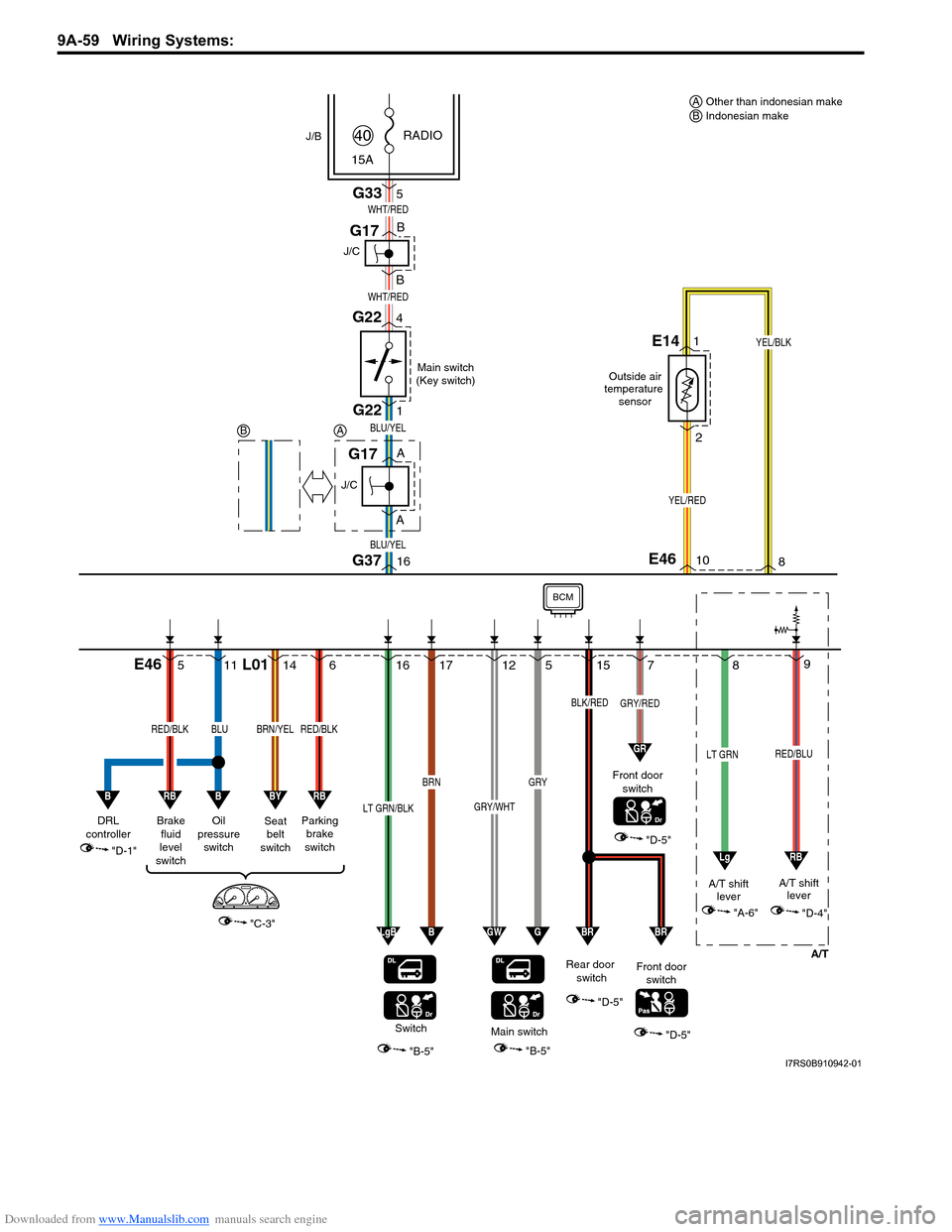
Downloaded from www.Manualslib.com manuals search engine 9A-59 Wiring Systems:
9
15 7
"D-5"
"A-6"
A/T
GRY/RED
RED/BLU
16
A A
B
BG37
BLU/YEL
BLU/YEL
J/C
G17
J/C
G17
G22
G22
1
4
Main switch
(Key switch)
RADIO
G335
15A
40
WHT/RED
WHT/RED
YEL/RED
YEL/BLK1E14
2
Outside air
temperature sensor
"B-5"
Switch
6L0114
1617125
RED/BLKBRN/YEL
LT GRN/BLK
BRN
GRY/WHT
GRY
Parking
brake
switch
Seat
belt
switch
"C-3"
"D-1"
RBBY
8
LT GRN
A/T shift lever A/T shift
lever
115
"D-4"
LgRB
GR
Oil
pressure switchBrakefluid
level
switch
B
DRL
controller
B
E46
10E468
LgBBGWG
Main switch
"B-5"
Front door switch
Front door switch
Rear door switch
"D-5"
"D-5"
BRBR
BLK/RED
J/B
BCM
BLURED/BLK
RB
Other than indonesian make
Indonesian make
A
AB
B
I7RS0B910942-01
Page 1231 of 1496

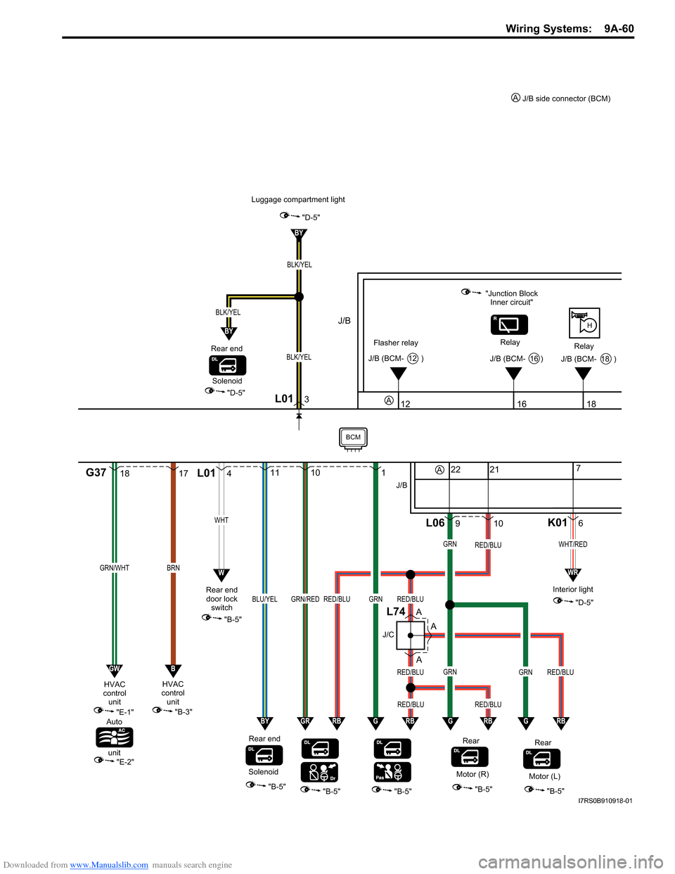
Downloaded from www.Manualslib.com manuals search engine Wiring Systems: 9A-60
1817
GRN/WHTBRN
"E-1"
"E-2"
HVAC
control unit
Auto
unit
G37
Flasher relay Relay
Relay
H
12
"Junction Block
Inner circuit"
J/B (BCM- 12 )J/B (BCM- 18 )
1618
J/B (BCM- 16 )
J/B
"B-5""B-5""B-5""B-5"
11
9
L06
22
10
21
Rear
J/B
GRN
GRN
RED/BLU
RED/BLURED/BLU
RED/BLUGRNRED/BLU
GRN
110
GRN/REDRED/BLURED/BLUBLU/YEL
Rear end
L014
WHT
Rear end
door lock switch
3
"D-5"
BLK/YEL
L01
Luggage compartment light
7
6K01
Interior light
"D-5"
WHT/RED
WR
J/B side connector (BCM)
A
A
A
BY
GWB
W
BYGRRBGGRBGRBGRB
"B-5"
SolenoidMotor (R)
"B-5"
Rear
Motor (L)
"B-3"
HVAC
control unit
BCM
BLK/YEL
BY
BLK/YEL
"D-5"
Solenoid
Rear end
A
A
A
J/C
L74
I7RS0B910918-01
Page 1253 of 1496

Downloaded from www.Manualslib.com manuals search engine Wiring Systems: 9A-82
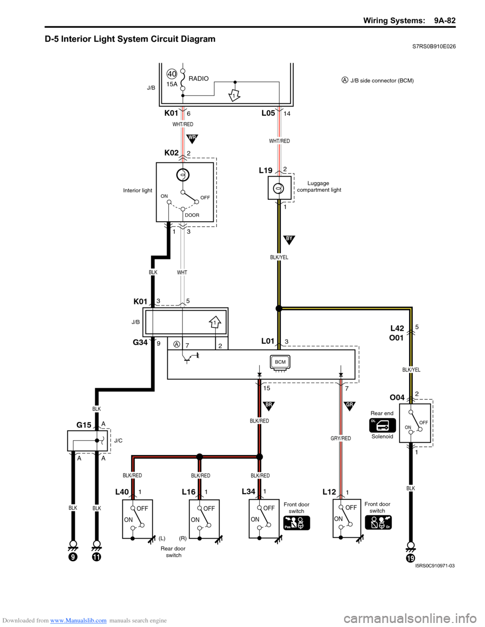
D-5 Interior Light System Circuit DiagramS7RS0B910E026
15A
40RADIO
J/B
OFF
DOOR
ON
K02 K012 6
3
1
Interior light
15
7
OFF
ON
OFF
ON
L121
1
GRY/RED
BLK
OFF
ONOFF
ON
L16 L341L401
Rear door
switch Front door
switch
BLK/RED
BLK
BLK
BLK
L0514
WHT/RED
G15
J/C
A
A
5
7G34
K01
J/B
L01
Luggage
compartment light
2
1
3L19
WHT/RED
BLK/YEL
WHT
1119
OFF
ON
O042
L42
O015
1
BLK/YEL
3
Solenoid
2
1
1
J/B side connector (BCM)
A
(L) (R) Front door
switch
A
BLK/REDBLK/REDBLK/RED
Rear end
9
BRGR
9
BLK
A
BY
WR
BCM
I5RS0C910971-03
Page 1322 of 1496

Downloaded from www.Manualslib.com manuals search engine 9D-5 Wipers / Washers:
Windshield Wiper Motor InspectionS7RS0B9406005
NOTE
Make sure that battery voltage is 12 V or
more.
1) Disconnect negative (–) cable at battery.
2) Remove windshield wiper arms with wiper blades
referring to “Windshield Wiper Removal and
Installation”.
3) Remove cowl top garnish referring to “Cowl Top Components in Section 9K”.
4) Disconnect coupler from windshield wiper motor.
5) Reinstall windshield wiper arms with wiper blade. For
details, refer to Step 4) of “Installation” in “Windshield
Wiper Removal and Installation”.
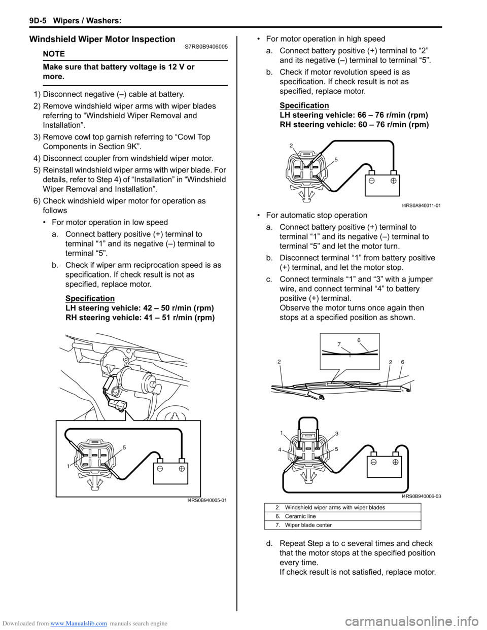
6) Check windshield wiper motor for operation as
follows
• For motor operation in low speed
a. Connect battery positive (+) terminal to terminal “1” and its negative (–) terminal to
terminal “5”.
b. Check if wiper arm reciprocation speed is as specification. If check result is not as
specified, replace motor.
Specification
LH steering vehicle: 42 – 50 r/min (rpm)
RH steering vehicle: 41 – 51 r/min (rpm) • For motor operation in high speed
a. Connect battery positive (+) terminal to “2” and its negative (–) terminal to terminal “5”.
b. Check if motor revolution speed is as specification. If chec k result is not as
specified, replace motor.
Specification
LH steering vehicle: 66 – 76 r/min (rpm)
RH steering vehicle: 60 – 76 r/min (rpm)
• For automatic stop operation a. Connect battery positive (+) terminal to terminal “1” and its negative (–) terminal to
terminal “5” and let the motor turn.
b. Disconnect terminal “1” from battery positive (+) terminal, and let the motor stop.
c. Connect terminals “1” and “3” with a jumper wire, and connect terminal “4” to battery
positive (+) terminal.
Observe the motor turns once again then
stops at a specified position as shown.
d. Repeat Step a to c several times and check that the motor stops at the specified position
every time.
If check result is not satisfied, replace motor.
1 5
I4RS0B940005-012. Windshield wiper arms with wiper blades
6. Ceramic line
7. Wiper blade center
2
5
I4RS0A940011-01
4 5
31
6
6
7
2
2
I4RS0B940006-03