2006 SUZUKI SWIFT Back up
[x] Cancel search: Back upPage 272 of 1496

Downloaded from www.Manualslib.com manuals search engine 1B-5 Aux. Emission Control Devices:
PCV Valve InspectionS7RS0B1206010
NOTE
Be sure to check that there is no obstruction
in PCV valve or its hoses before checking
IAC duty, for obstructed PCV valve or hose
hampers its accurate adjustment.
1) Detach air cleaner assembly.
2) Disconnect PCV valve from cylinder head cover and install plug to head cover hole.
3) Install air cleaner assembly temporarily.
4) Run engine at idle.
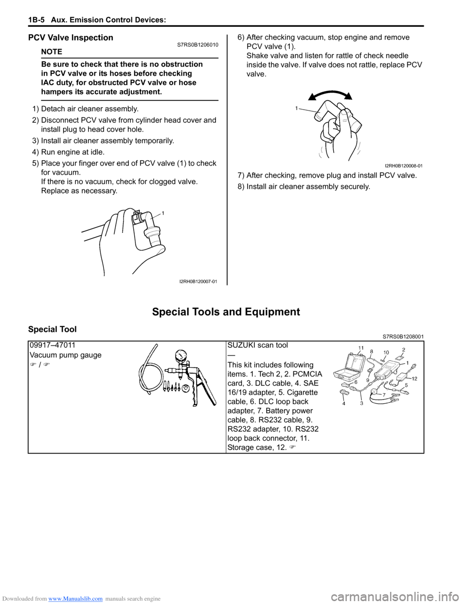
5) Place your finger over end of PCV valve (1) to check for vacuum.
If there is no vacuum, ch eck for clogged valve.
Replace as necessary. 6) After checking vacuum, stop engine and remove
PCV valve (1).
Shake valve and listen for rattle of check needle
inside the valve. If valve does not rattle, replace PCV
valve.
7) After checking, remove plug and install PCV valve.
8) Install air cleaner assembly securely.
Special Tools and Equipment
Special ToolS7RS0B1208001
I2RH0B120007-01
I2RH0B120008-01
09917–47011 SUZUKI scan tool
Vacuum pump gauge —
�) / �) This kit includes following
items. 1. Tech 2, 2. PCMCIA
card, 3. DLC cable, 4. SAE
16/19 adapter, 5. Cigarette
cable, 6. DLC loop back
adapter, 7. Battery power
cable, 8. RS232 cable, 9.
RS232 adapter, 10. RS232
loop back connector, 11.
Storage case, 12. �)
Page 275 of 1496

Downloaded from www.Manualslib.com manuals search engine Engine Electrical Devices: 1C-3
Throttle Valve Operation Check1) Remove air cleaner outlet hose.
2) Turn OFF ignition switch.
3) Move throttle valve with finger to its full open position and check that it moves smoothly.
4) Move throttle valve with fi nger to its completely
closed position and check that it moves smoothly.
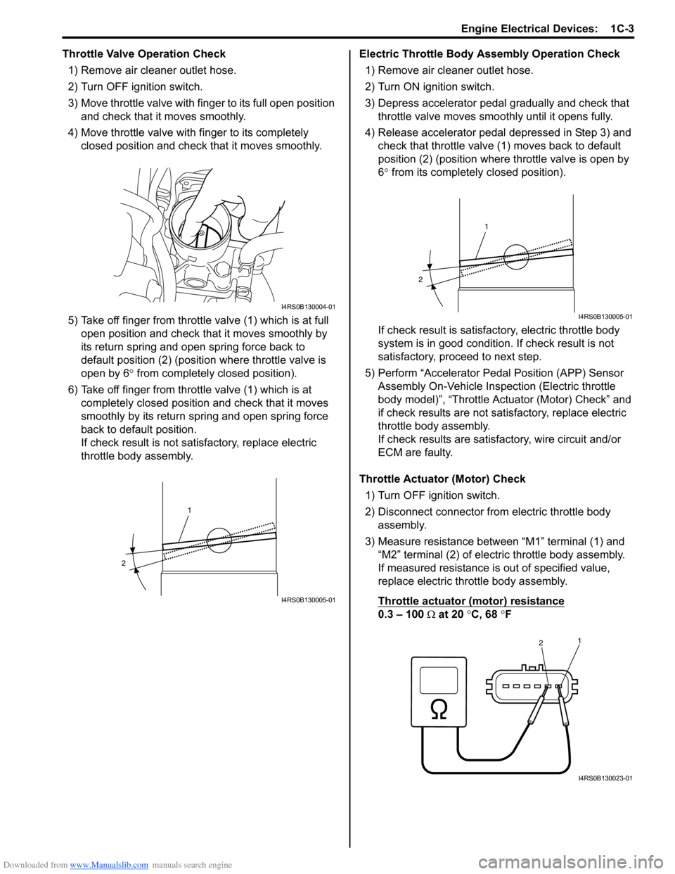
5) Take off finger from throttle valve (1) which is at full open position and check that it moves smoothly by
its return spring and open spring force back to
default position (2) (positio n where throttle valve is
open by 6 ° from completely closed position).
6) Take off finger from throttle valve (1) which is at completely closed position and check that it moves
smoothly by its return spring and open spring force
back to default position.
If check result is not satisfactory, replace electric
throttle body assembly. Electric Throttle Body
Assembly Operation Check
1) Remove air cleaner outlet hose.
2) Turn ON ignition switch.
3) Depress accelerator pedal gradually and check that throttle valve moves smoo thly until it opens fully.
4) Release accelerator pedal depressed in Step 3) and check that throttle valve (1) moves back to default
position (2) (position where throttle valve is open by
6° from its completely closed position).
If check result is satisfactory, electric throttle body
system is in good condition. If check result is not
satisfactory, proceed to next step.
5) Perform “Accelerator Pe dal Position (APP) Sensor
Assembly On-Vehicle Inspection (Electric throttle
body model)”, “Throttle Actuator (Motor) Check” and
if check results are not satisfactory, replace electric
throttle body assembly.
If check results are satisfactory, wire circuit and/or
ECM are faulty.
Throttle Actuator (Motor) Check 1) Turn OFF ignition switch.
2) Disconnect connector from electric throttle body assembly.
3) Measure resistance between “M1” terminal (1) and “M2” terminal (2) of electric throttle body assembly.
If measured resistance is out of specified value,
replace electric throttle body assembly.
Throttle actuator (motor) resistance
0.3 – 100 Ω at 20 °C, 68 °F
I4RS0B130004-01
1
2
I4RS0B130005-01
1
2
I4RS0B130005-01
2 1
I4RS0B130023-01
Page 302 of 1496

Downloaded from www.Manualslib.com manuals search engine 1D-17 Engine Mechanical:
Engine Assembly Removal and InstallationS7RS0B1406011
NOTE
After replacing electric throttle body
assembly, perform calibration of throttle
valve referring to “Electric Throttle Body
System Calibration in Section 1C”.
Removal1) Relieve fuel pressure according to “Fuel Pressure Relief Procedure in Section 1G”.
2) Disconnect negative and pos itive cable at battery.
3) Remove battery and tray.
4) Remove engine hood after disconnecting windshield washer hose.
5) Remove right and left side engine under covers.
6) Remove A/C compressor belt by referring to “Compressor Drive Belt Remo val and Installation in
Section 7B” or “Compressor Drive Belt Removal and
Installation in Section 7B”.
7) Drain engine oil, transaxle oil and coolant.
8) Remove cowl top plate referring to “Cowl Top Components in Section 9K”.
9) Remove air cleaner assembly referring to “Air Cleaner Components”.
10) With hose connected, detach A/C compressor from its bracket (A/C model) referring to “Compressor
Assembly Removal and Installation in Section 7B” or
“Compressor Assembly Removal and Installation in
Section 7B”.
CAUTION!
Suspend removed A/C compressor at a place
where no damage will be caused during
removal and installation of engine assembly.
11) Remove intake manifold rear stiffener (1) from intake manifold and cylinder block. 12) Disconnect the following electric wires:
• MAP sensor (1)
• ECT sensor (2)
•EGR valve (3)
• CMP sensor (4)
• Electric throttle body assembly (5)
• Ignition coil assembly (6)
• Injectors (7)
• Heated oxygen sensor No. 2 (8) and No. 1 (9)
• Oil control valve (10)
• Engine oil pressure switch (11)
• CKP sensor (12)
• Knock sensor (13)
• Back up light switch (14)
• Generator (15)
• Starting motor (16)
• Ground terminal (17) from intake manifold
• Battery ground terminal (18) from exhaust manifold
• Battery ground cable (19) from transaxle
• Magnet clutch switch of A/C compressor (A/C model)
• Each wire harness clamps
• Output shaft speed sensor (VSS) (34) (A/T model)
• Solenoid valve (33) (A/T model)
• Transmission range sensor (32) (A/T model)
• Input shaft speed sensor (31) (A/T model)
13) Remove fuse box from its bracket.
14) Disconnect the following cables: • Gear select control cable (23) (M/T model)
• Gear shift control cable (24) (M/T model)
• A/T select cable (A/T model)
15) Disconnect the following hoses: • Brake booster hose (26) from intake manifold
• Radiator inlet and outlet hoses (20) from each pipe
• Heater inlet and outlet hoses (21) from each pipe
• Fuel feed hoses (22) from fuel feed pipe
• EVAP canister purge valve hose (30) from purge pipe
• A/T fluid cooler hoses (A/T model)
16) With hose connected, detach clutch operating cylinder (25). (M/T model)
CAUTION!
Suspend removed clutch operating cylinder
at a place where no damage will be caused
during removal and installation of engine
assembly.
1
I6RS0B141014-01
Page 305 of 1496

Downloaded from www.Manualslib.com manuals search engine Engine Mechanical: 1D-20
15) Install A/C compressor to its bracket (if equipped) referring to “Compressor Assembly Removal and
Installation in Section 7B” or “Compressor Assembly
Removal and Installa tion in Section 7B”.
16) Adjust A/C compressor belt tension (if equipped) referring to “Compressor Drive Belt Inspection and
Adjustment in Section 7B” or “Compressor Drive Belt
Inspection and Adjustment in Section 7B”.
17) Check to ensure that a ll removed parts are back in
place.
Reinstall any necessary parts which have not been
reinstalled.
18) Refill cooling system with coolant referring to “Cooling System Flush and Refill in Section 1F”. 19) Refill engine with engine oil
referring to “Engine Oil
and Filter Change in Section 0B”.
20) Refill transaxle with transa xle oil referring to“Manual
Transaxle Oil Change in Section 5B” or “A/T Fluid
Change in Section 5A”.
21) Install battery and tray.
22) Connect positive and negative cable at battery.
23) Install engine hood and connect windshield washer hose.
24) Verify that there is no fu el leakage, coolant leakage,
oil leakage and exhaust gas leakage at each
connection.
Timing Chain Cover ComponentsS7RS0B1406012
I6RS0C140015-02
1. Crankshaft pulley bolt 13. Oil gallery pipe No.2 bolt
2. Crankshaft pulley 14. Oil gallery pipe No.3
3. Oil seal : Apply engine oil to oil seal lip. 15. Oil gallery pipe No.3 bolt
4. Timing chain cover : Apply sealant 99000-31140 to the mating surface of cylinder and cylinder head.
: Apply sealant 99000-31260 to the mating surface of timing chain cover referring to the
figure of Step 4) of “Installation” under “Timing Chain Cover Removal and Installation”. 16. O-ring
: Apply engine oil.
5. Pin 17. Oil control valve
6. Cap bolt 18. Oil control valve mounting nut
7. Timing chain cover mounting bolts 19. Cap
8. Timing chain cover mounting nut : 11 N ⋅m (1.1 kgf-m, 8.0 lb-ft)
9. Oil gallery pipe No.1 :25 N⋅m (2.5 kgf-m, 18.0 lb-ft)
Page 315 of 1496

Downloaded from www.Manualslib.com manuals search engine Engine Mechanical: 1D-30
Installation1) Install tappets and shims to cylinder head. Apply engine oil around tappet and then install it to
cylinder head.
NOTE
When installing shim, make sure to direct
shim No. side toward tappet.
2) Install camshaft bearing (1) to cylinder head.
CAUTION!
Do not apply engine oil to camshaft bearing
back.
Only a upper half bearing of intake camshaft
bearing No.1 has some holes. Other
bearings.
3) Install intake camshaft (1) and exhaust camshaft (2). Align knock pin (3) and match mark (4) with notches
(5) as shown in figure.
NOTE
Before installing camshafts, turn crankshaft
until key position faces upward.
Refer to “Timing Chain and Chain Tensioner
Removal and Installation”.
4) Apply engine oil to sliding surface of each camshaft and camshaft journal then install them as shown in
figure.
5) Install camshaft housing pins (1) as shown in figure.
6) Check position of camshaft housings. Embossed marks are provided on each camshaft
housing, indicating position and direction for
installation. Install housings as indicated by these
marks.I2RH0B140075-01
1
I3RH0B140039-01
“a”: Approx. 30 °
A: I: Intake side or E: Exhaust side
B: Position from timing chain side
C: Pointing to timing chain side
1 2
3 4
5
“a”
I6RS0C140019-01
I3RM0A140033-01
I2RH0B140078-01
Page 340 of 1496

Downloaded from www.Manualslib.com manuals search engine 1D-55 Engine Mechanical:
Installation
NOTE
• Use new bearing cap No.1 bolts. They are deformed once they are used because they
are plastic deformation tightening bolts.
• All parts to be insta lled must be perfectly
clean.
• Be sure to oil crankshaft journals, journal bearings, thrust bearings, crankpins,
connecting rod bearings, pistons, piston
rings and cylinder bores.
• Journal bearings, bearing caps, connecting rods, rod bearings, rod bearing
caps, pistons and piston rings are in
combination sets. Do not disturb such
combination and make sure that each part
goes back to where it came from, when
installing.
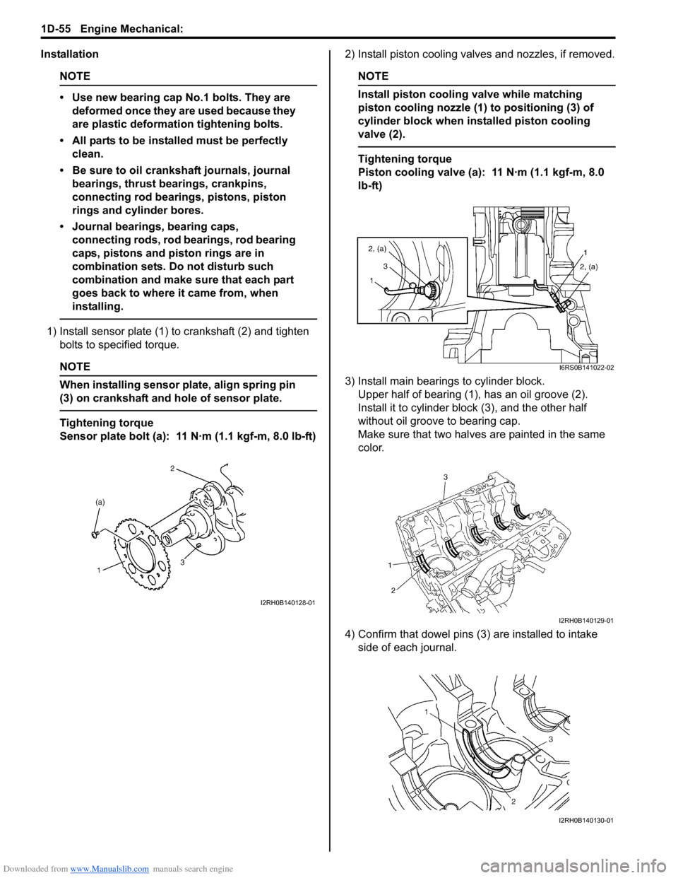
1) Install sensor plate (1) to crankshaft (2) and tighten bolts to spec ified torque.
NOTE
When installing sensor plate, align spring pin
(3) on crankshaft and hole of sensor plate.
Tightening torque
Sensor plate bolt (a): 11 N·m (1.1 kgf-m, 8.0 lb-ft) 2) Install piston cooling valves and nozzles, if removed.
NOTE
Install piston cooling valve while matching
piston cooling nozzle (1) to positioning (3) of
cylinder block when installed piston cooling
valve (2).
Tightening torque
Piston cooling valve (a): 11 N·m (1.1 kgf-m, 8.0
lb-ft)
3) Install main bearings to cylinder block. Upper half of bearing (1), has an oil groove (2).
Install it to cylinder block (3), and the other half
without oil groove to bearing cap.
Make sure that two halves are painted in the same
color.
4) Confirm that dowel pins (3 ) are installed to intake
side of each journal.
I2RH0B140128-01
I6RS0B141022-02
I2RH0B140129-01
I2RH0B140130-01
Page 364 of 1496

Downloaded from www.Manualslib.com manuals search engine 1F-1 Engine Cooling System:
Engine
Engine Cooling System
General Description
Cooling System DescriptionS7RS0B1601001
The cooling system consists of the radiator cap, radiator, coolant reservoir, hoses, water pump, cooling fan and
thermostat. The radiator is of tube-and-fin type.
Coolant DescriptionS7RS0B1601002
WARNING!
• Do not remove radiator cap to check engine coolant level; check coolant visually at the see-through coolant reservoir. Coolant should be added only to reservoir as necessary.
• As long as there is pressure in the cooling system, the temperature can be considerably higher than the boiling temperature of the solution in the radiator without causing the solution to boil. Removal
of the radiator cap while engine is hot and pressure is high will cause the solution to boil
instantaneously and possibly with explosive force, spewing the solution over engine, fenders and
person removing cap. If the solution contains flammable anti-freeze such as alcohol (not
recommended for use at any time), there is also the possibility of causing a serious fire.
• Check to make sure that engine coolant temperature is cold before removing any part of cooling system.
• Also be sure to disconnect negative cable from battery terminal before removing any part.
The coolant recovery system is standard. The coolant in the radiator expands with heat, and the coolant is overflowed
to the reservoir.
When the system cools down, the coolant is drawn back into the radiator.
The cooling system has be en filled with a quality coolant that is a 50/50 mixture of water and ethylene glycol
antifreeze.
This 50/50 mixture coolant solution provides freezing protection to –36 °C (–33 °F).
• Maintain cooling system freeze protection at –36 °C (–33 °F) to ensure protection against corrosion and loss of
coolant from boiling. This should be done even if freezing temperatures are not expected.
• Add ethylene glycol base coolant when coolant has to be added because of coolant loss or to provide added protection against freezing at temperature lower than –36 °C (–33 °F).
NOTE
• Alcohol or methanol base coolant or plain water alone should not be used in cooling system at any
time as damage to cooling system could occur.
• Coolant must be mixed with deminerated water or distilled water.
Anti-freeze proportioning table
For M/T model For A/T model
Freezing temperature °
C –36 –36
° F –33 –33
Anti-freeze / Anti-corrosion coolant concentration % 50 50
Ratio of compound to cooling water ltr. 3.10/3.10 3.05/3.05
US pt. 6.55/6.55 6.44/6.44
Imp pt. 5.46/5.46 5.37/5.37
Page 376 of 1496

Downloaded from www.Manualslib.com manuals search engine 1G-1 Fuel System:
Engine
Fuel System
Precautions
Precautions on Fuel System ServiceS7RS0B1700001
WARNING!
Before attempting service of any type on fuel system, the following should be always observed in
order to reduce the risk of fire and personal injury.
• Disconnect negative cable at battery.
• Do not smoke, and place no smoking signs near work area.
• Be sure to have CO
2 fire extinguisher handy.
• Be sure to perform work in a well-ventilated area and away from any open flames (such as gas hot heater).
• Wear safety glasses.
• To relieve fuel vapor pressure in fuel tank, remove fuel filler cap from fuel filler neck and then
reinstall it.
• As fuel feed line is still under high fuel pr essure even after stopping engine, loosening or
disconnecting fuel feed line directly may cause dangerous spout of fuel. Before loosening or
disconnecting fuel feed line, make sure to relieve fuel pressure referring to “Fuel Pressure Relief
Procedure”.
• A small amount of fuel may be released when the fuel line is disconnected. In order to reduce the risk of personal injury, cover a shop cloth to the fitting to be disconnected. Be sure to put that cloth
in an approved container after disconnecting.
• Never run engine with fuel pump relay disconnected when engine and exhaust system are hot.
• Note that fuel hose connection varies with each type of pipe. Be sure to connect and clamp each hose correctly referring to “Fuel Hose Disconnecting and Reconnecting”.
After connecting, make sure that it has no twist or kink.
• When installing inje ctor or fuel feed pipe, lubr icate its O-ring with gasoline.
General Description
Fuel System DescriptionS7RS0B1701001
CAUTION!
This engine requires the unleaded fuel only.
The leaded and/or low lead fuel can result in
engine damage and reduce the effectiveness
of the emission control system.
The main components of the fuel system are fuel tank,
fuel pump assembly (with fuel filter, fuel level gauge, fuel
pressure regulator, fuel feed line and fuel vapor line.
For the details of fuel flow, refer to “Fuel Delivery System
Diagram”.
Fuel Delivery System DescriptionS7RS0B1701002
The fuel delivery system consists of the fuel tank, fuel
pump assembly (with built-in f uel filter and fuel pressure
regulator), delivery pipe, injectors and fuel feed line.
The fuel in the fuel tank is pumped up by the fuel pump,
sent into delivery pipe and injected by the injectors.
As the fuel pump assembly is equipped with built-in fuel
filter and fuel pressure regulator, the fuel is filtered and
its pressure is regulated before being sent to the feed
pipe.
The excess fuel at fuel pressure regulation process is
returned back into the fuel tank.
Also, fuel vapor generated in fuel tank is led through the
fuel vapor line into the EVAP canister.
For system diagram, refer to “Fuel Delivery System
Diagram”.