2006 SUZUKI SWIFT Torque spec
[x] Cancel search: Torque specPage 1032 of 1496
Downloaded from www.Manualslib.com manuals search engine 8A-1 Seat Belts:
Restraint
Seat Belts
Precautions
Precautions on Service and Diagnosis of Seat
Belt
S7RS0B8100001
WARNING!
If replacing seat belt is necessary, replace
buckle and seat belt assembly together as a
set. This is for the reason of ensuring locking
of tongue plate with buckle. If these parts are
replaced individually, such a locking
condition may become unreliable. For this
reason, SUZUKI will supply only the spare
buckle and seat belt assembly in a set part.
Before servicing or replacing seat belts, refer to the
following precautionary items.
• Seat belts should be normal relative to strap retractor and buckle portions. • Keep sharp edges and damaging objects away from
belts.
• Avoid bending or damaging any portion of belt buckle or latch plate.
• Do not bleach or dye belt webbing. (Use only mild soap and lukewarm water to clean it.)
• When installing a seat belt anchor bolt, it should be tightened by hand at first to prevent cross-threading
and then to specified torque.
• Do not attempt any repair s on retractor mechanisms
or retractor covers. Replace defective assemblies with
new replacement parts.
• Keep belts dry and clean at all times.
• If there exist any parts in question, replace such parts.
• Replace belts whose webbing is cut or otherwise damaged.
• Do not put anything into trim panel opening which seat belt webbing passes through.
General Description
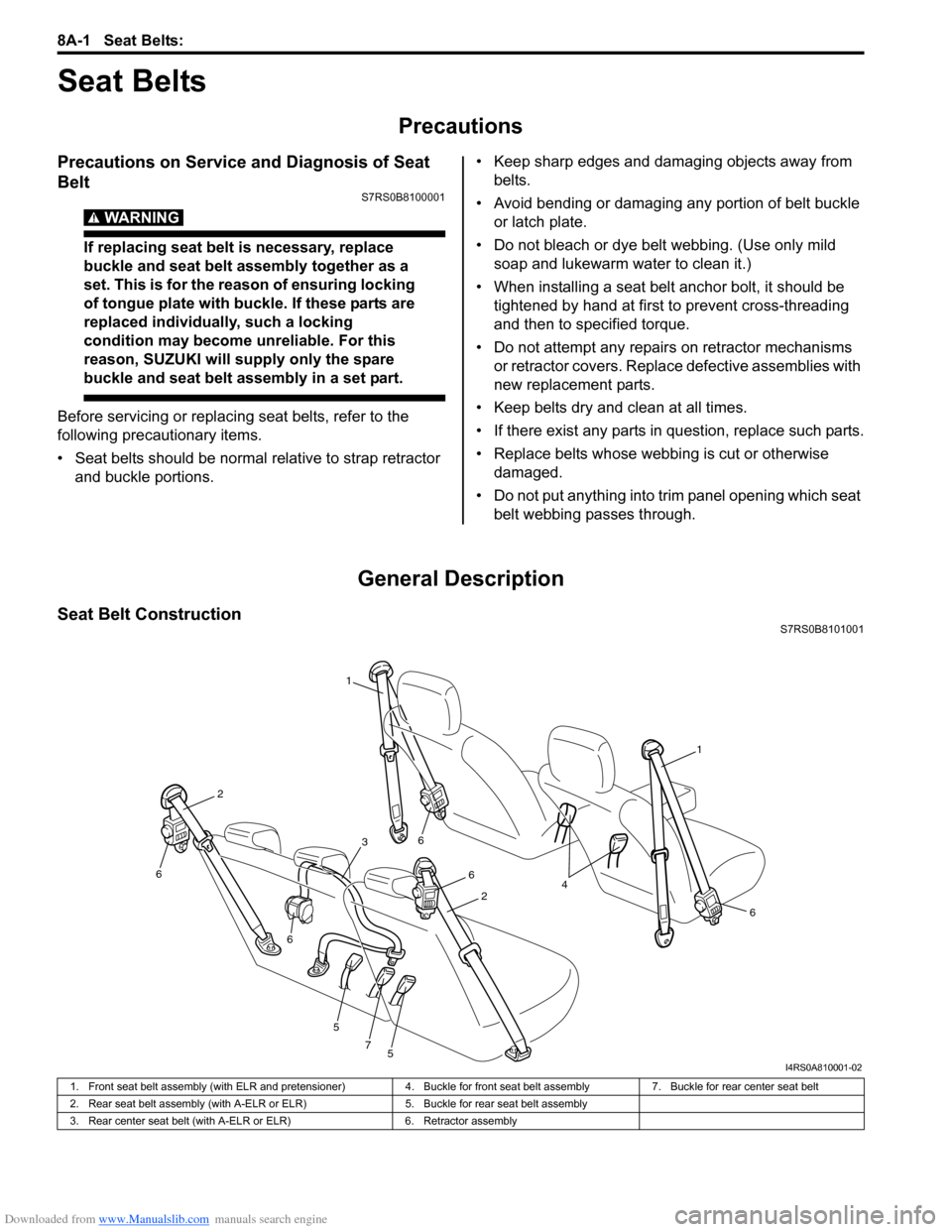
Seat Belt ConstructionS7RS0B8101001
1
1
6
6
6
5
5
7
6
6
2
2
3
4
I4RS0A810001-02
1. Front seat belt assembly (with ELR and pretensioner) 4. Buckle for front seat belt assembly7. Buckle for rear center seat belt
2. Rear seat belt assembly (with A-ELR or ELR) 5. Buckle for rear seat belt assembly
3. Rear center seat belt (with A-ELR or ELR) 6. Retractor assembly
Page 1036 of 1496
Downloaded from www.Manualslib.com manuals search engine 8A-5 Seat Belts:
Seat Belt
• The seat belt webbing or strap should be free from damage.
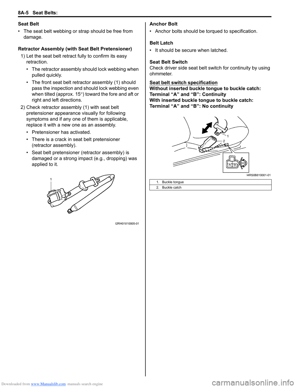
Retractor Assembly (with Seat Belt Pretensioner) 1) Let the seat belt retract fully to confirm its easy retraction.
• The retractor assembly should lock webbing when
pulled quickly.
• The front seat belt retractor assembly (1) should pass the inspection and should lock webbing even
when tilted (approx. 15 °) toward the fore and aft or
right and left directions.
2) Check retractor assembly (1) with seat belt pretensioner appearance visually for following
symptoms and if any one of them is applicable,
replace it with a new one as an assembly.
• Pretensioner has activated.
• There is a crack in seat belt pretensioner (retractor assembly).
• Seat belt pretensioner (retractor assembly) is damaged or a strong impact (e.g., dropping) was
applied to it. Anchor Bolt
• Anchor bolts should be torqued to specification.
Belt Latch
• It should be secure when latched.
Seat Belt Switch
Check driver side seat belt s
witch for continuity by using
ohmmeter.
Seat belt switch specification
Without inserted buckle tongue to buckle catch:
Terminal “A” and “B”: Continuity
With inserted buckle tongue to buckle catch:
Terminal “A” and “B”: No continuity
I2RH01810005-01
1. Buckle tongue
2. Buckle catch
I4RS0B810001-01
Page 1038 of 1496
Downloaded from www.Manualslib.com manuals search engine 8A-7 Seat Belts:
Rear Seat Belt Removal and InstallationS7RS0B8106005
WARNING!
Be sure to read “Precautions on Service and
Diagnosis of Seat Belt” before starting to
work and observe every precaution during
work.
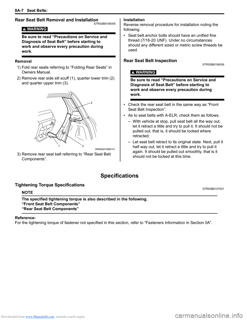
Removal1) Fold rear seats referring to “Folding Rear Seats” in Owners Manual.
2) Remove rear side sill scuff (1), quarter lower trim (2)
and quarter upper trim (3).
3) Remove rear seat belt referring to “Rear Seat Belt Components”. Installation
Reverse removal procedure for installation noting the
following.
• Seat belt anchor bolts should have an unified fine
thread (7/16-20 UNF). Under no circumstances
should any different sized or metric screw threads be
used.Rear Seat Belt InspectionS7RS0B8106006
WARNING!
Be sure to read “Precautions on Service and
Diagnosis of Seat Belt” before starting to
work and observe every precaution during
work.
• Check the rear seat belt in the same way as “Front Seat Belt Inspection”.
• As to seat belts with A-ELR, check them as follows. – With vehicle at stop, pull seat belt all the way out, let it retract a little and try to pull it. It should not be
pulled out, that is, it should be locked where
retracted.
– Let seat belt retract to its original state. Next, pull it
half way out, let it retrac t a little and try to pull it
again. It should be pulled out smoothly, that is it
should not be locked at this time.
Specifications
Tightening Torque SpecificationsS7RS0B8107001
NOTE
The specified tightening torque is also described in the following.
“Front Seat Belt Components”
“Rear Seat Belt Components”
Reference:
For the tightening torque of fastener not specified in this section, refer to “Fasteners Information in Section 0A”.
3
2
1
I4RS0A810004-01
Page 1040 of 1496
Downloaded from www.Manualslib.com manuals search engine 8B-2 Air Bag System:
Precautions on Handling and Storage of Air Bag
System Components
S7RS0B8200002
SDM
WARNING!
Never power up air bag system when SDM is
not rigidly attached to the vehicle. Otherwise,
personal injury may result.
CAUTION!
After detecting one time of such collision as
to meet deployment conditions, SDM must
not be used. Refer to “Air Bag Diagnostic
System Check” when checking SDM.
• Never attempt disassembly of SDM.
• When storing SDM, select a place where neither high temperature nor high humidity is anticipated and oil,
water and dust are kept off.
• If SDM has been dropped, replace it with a new one.
• If SDM installation part of floor was damaged, repair that part completely before reinstallation.
• All SDM and mounting bracket fasteners must be carefully torqued and the arrow must be pointed
toward the front of the vehicle to ensure proper
operation of the air bag system. Live (Undeployed) Air Bag (Inflator) Modules
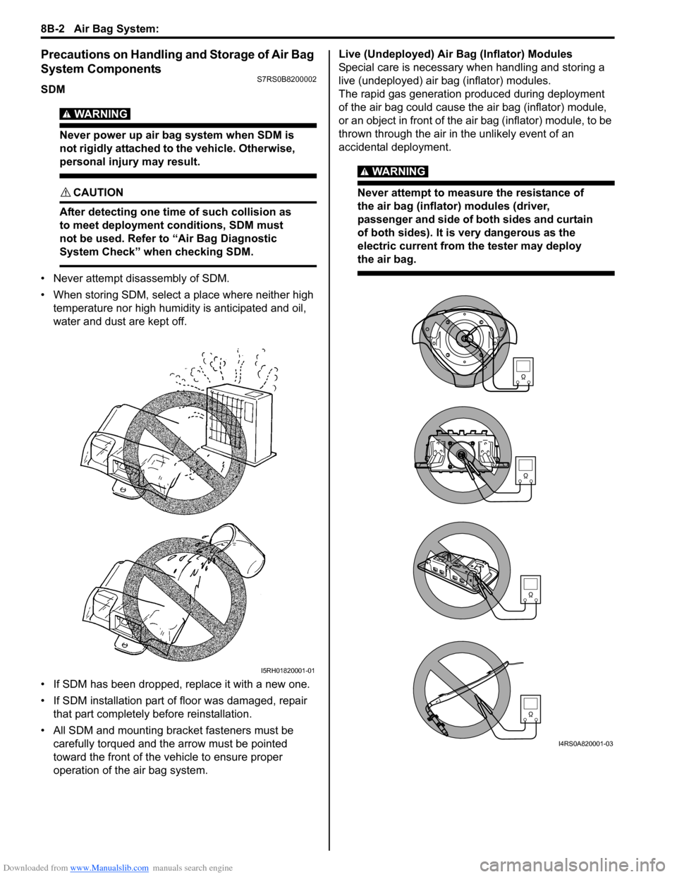
Special care is necessary when handling and storing a
live (undeployed) air bag (inflator) modules.
The rapid gas generation produced during deployment
of the air bag could cause the air bag (inflator) module,
or an object in front of the air bag (inflator) module, to be
thrown through the air in the unlikely event of an
accidental deployment.
WARNING!
Never attempt to measure the resistance of
the air bag (inflator) modules (driver,
passenger and side of both sides and curtain
of both sides). It is
very dangerous as the
electric current from the tester may deploy
the air bag.
I5RH01820001-01
I4RS0A820001-03
Page 1139 of 1496
Downloaded from www.Manualslib.com manuals search engine Air Bag System: 8B-101
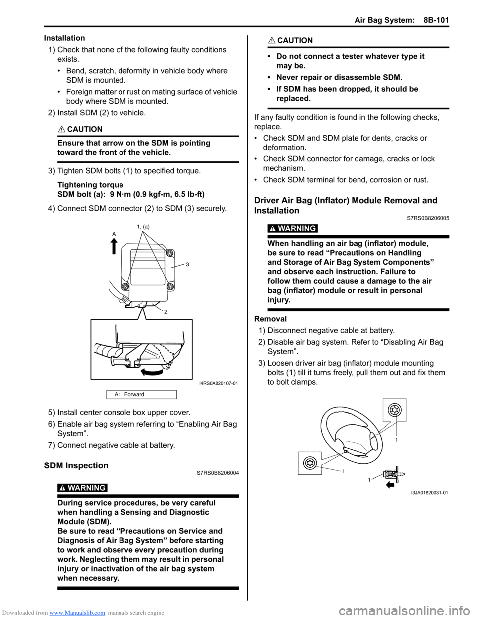
Installation1) Check that none of the following faulty conditions exists.
• Bend, scratch, deformity in vehicle body where SDM is mounted.
• Foreign matter or rust on mating surface of vehicle body where SDM is mounted.
2) Install SDM (2) to vehicle.
CAUTION!
Ensure that arrow on the SDM is pointing
toward the front of the vehicle.
3) Tighten SDM bolts (1) to specified torque.
Tightening torque
SDM bolt (a): 9 N·m (0.9 kgf-m, 6.5 lb-ft)
4) Connect SDM connector (2) to SDM (3) securely.
5) Install center console box upper cover.
6) Enable air bag system referring to “Enabling Air Bag System”.
7) Connect negative cable at battery.
SDM InspectionS7RS0B8206004
WARNING!
During service procedures, be very careful
when handling a Sensing and Diagnostic
Module (SDM).
Be sure to read “Precautions on Service and
Diagnosis of Air Bag System” before starting
to work and observe every precaution during
work. Neglecting them ma y result in personal
injury or inactivation of the air bag system
when necessary.
CAUTION!
• Do not connect a tester whatever type it may be.
• Never repair or disassemble SDM.
• If SDM has been dropped, it should be replaced.
If any faulty condition is fo und in the following checks,
replace.
• Check SDM and SDM plate for dents, cracks or deformation.
• Check SDM connector for damage, cracks or lock mechanism.
• Check SDM terminal for bend, corrosion or rust.
Driver Air Bag (Inflator) Module Removal and
Installation
S7RS0B8206005
WARNING!
When handling an air bag (inflator) module,
be sure to read “Precautions on Handling
and Storage of Air Bag System Components”
and observe each instruction. Failure to
follow them could cause a damage to the air
bag (inflator) module or result in personal
injury.
Removal 1) Disconnect negative cable at battery.
2) Disable air bag system. Re fer to “Disabling Air Bag
System”.
3) Loosen driver air bag (inflator) module mounting bolts (1) till it turns freely, pull them out and fix them
to bolt clamps.
A: Forward
2 3
A
1, (a)
I4RS0A820107-01
I3JA01820031-01
Page 1140 of 1496
Downloaded from www.Manualslib.com manuals search engine 8B-102 Air Bag System:
4) Remove air bag (inflator) module from steering wheel.
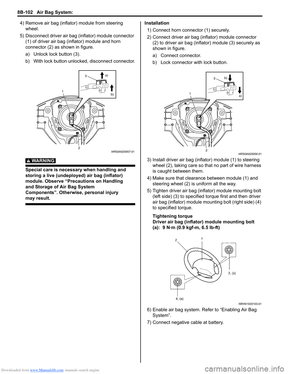
5) Disconnect driver air bag (inflator) module connector (1) of driver air bag (inflator) module and horn
connector (2) as shown in figure.
a) Unlock lock button (3).
b) With lock button unlocked, disconnect connector.
WARNING!
Special care is necessary when handling and
storing a live (undeployed) air bag (inflator)
module. Observe “Precautions on Handling
and Storage of Air Bag System
Components”. Otherwise, personal injury
may result.
Installation
1) Connect horn connector (1) securely.
2) Connect driver air bag (inflator) module connector (2) to driver air bag (inflator) module (3) securely as
shown in figure.
a) Connect connector.
b) Lock connector with lock button.
3) Install driver air bag (inflator) module (1) to steering wheel (2), taking care so t hat no part of wire harness
is caught between them.
4) Make sure that clearance between module (1) and steering wheel (2) is uniform all the way.
5) Tighten driver air bag (inflator) module mounting bolt (left side) (3) to specified torque first and then driver
air bag (inflator) module mounting bolt (right side) (4)
to specified torque.
Tightening torque
Driver air bag (inflator) module mounting bolt
(a): 9 N·m (0.9 kgf-m, 6.5 lb-ft)
6) Enable air bag system. Refer to “Enabling Air Bag System”.
7) Connect negative cable at battery.
1
2
3 a)
b)
I4RS0A820057-01
1
2
3 a)
b)
I4RS0A820058-01
I5RH01820103-01
Page 1144 of 1496
Downloaded from www.Manualslib.com manuals search engine 8B-106 Air Bag System:
4) Remove side-air bag (inflator) module from seat back.
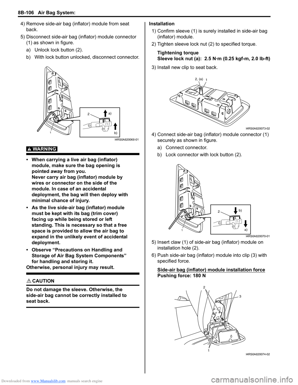
5) Disconnect side-air bag (inflator) module connector (1) as shown in figure.
a) Unlock lock button (2).
b) With lock button unlocked, disconnect connector.
WARNING!
• When carrying a live air bag (inflator) module, make sure the bag opening is
pointed away from you.
Never carry air bag (inflator) module by
wires or connector on the side of the
module. In case of an accidental
deployment, the bag will then deploy with
minimal chance of injury.
• As the live side-air bag (inflator) module must be kept with its bag (trim cover)
facing up while being stored or left
standing. This is necessary so that a free
space is provided to allow the air bag to
expand in the unlikely event of accidental
deployment.
• Observe “Precautions on Handling and Storage of Air Bag System Components”
for handling and storing it.
Otherwise, personal injury may result.
CAUTION!
Do not damage the sleeve. Otherwise, the
side-air bag cannot be correctly installed to
seat back.
Installation
1) Confirm sleeve (1) is surely installed in side-air bag (inflator) module.
2) Tighten sleeve lock nut (2) to specified torque.
Tightening torque
Sleeve lock nut (a): 2.5 N·m (0.25 kgf-m, 2.0 lb-ft)
3) Install new clip to seat back.
4) Connect side-air bag (inflator) module connector (1) securely as shown in figure.
a) Connect connector.
b) Lock connector wi th lock button (2).
5) Insert claw (1) of side-air bag (inflator) module on installation hole (2).
6) Push side-air bag (inflator) module into clip (3) with
specified force.
Side-air bag (inflator) module installation force
Pushing force: 180 N
2
1
a)
b)
I4RS0A820068-01
12, (a)
I4RS0A820073-02
1
2 a)
b)
I4RS0A820070-01
1
2
3
I4RS0A820074-02
Page 1146 of 1496
Downloaded from www.Manualslib.com manuals search engine 8B-108 Air Bag System:
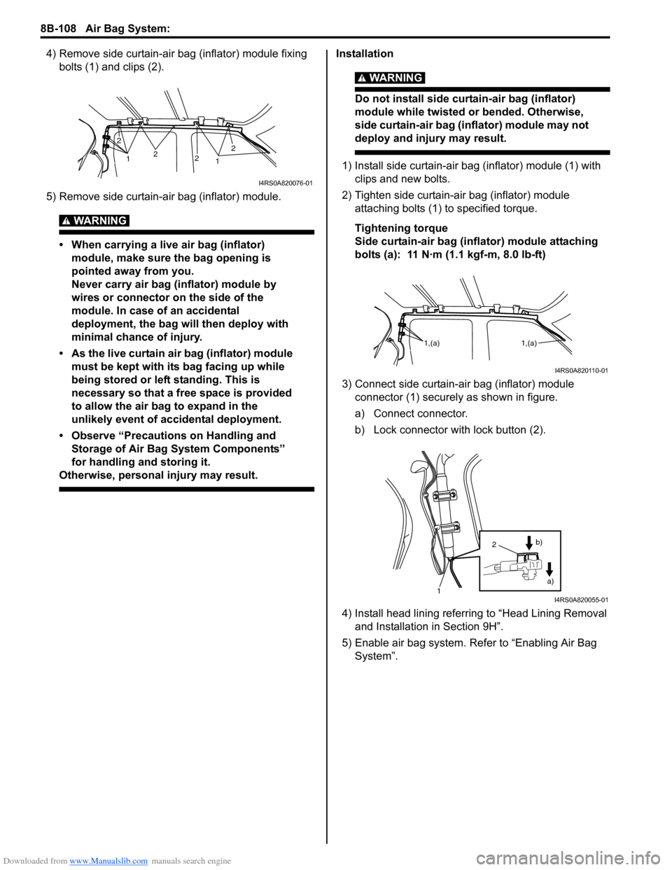
4) Remove side curtain-air bag (inflator) module fixing bolts (1) and clips (2).
5) Remove side curtain-air bag (inflator) module.
WARNING!
• When carrying a live air bag (inflator) module, make sure the bag opening is
pointed away from you.
Never carry air bag (inflator) module by
wires or connector on the side of the
module. In case of an accidental
deployment, the bag will then deploy with
minimal chance of injury.
• As the live curtain air bag (inflator) module must be kept with it s bag facing up while
being stored or left standing. This is
necessary so that a free space is provided
to allow the air bag to expand in the
unlikely event of accidental deployment.
• Observe “Precautions on Handling and Storage of Air Bag System Components”
for handling and storing it.
Otherwise, personal injury may result.
Installation
WARNING!
Do not install side curtain-air bag (inflator)
module while twisted or bended. Otherwise,
side curtain-air bag (inflator) module may not
deploy and injury may result.
1) Install side curtain-air bag (inflator) module (1) with
clips and new bolts.
2) Tighten side curtain-air bag (inflator) module attaching bolts (1) to specified torque.
Tightening torque
Side curtain-air bag (inflator) module attaching
bolts (a): 11 N·m (1.1 kgf-m, 8.0 lb-ft)
3) Connect side curtain-air bag (inflator) module connector (1) securely as shown in figure.
a) Connect connector.
b) Lock connector wi th lock button (2).
4) Install head lining referring to “Head Lining Removal and Installation in Section 9H”.
5) Enable air bag system. Refer to “Enabling Air Bag System”.1 2
2
22
1
I4RS0A820076-01
1,(a) 1,(a)
I4RS0A820110-01
1
2
a)
b)
I4RS0A820055-01