2006 SUZUKI SWIFT Cable
[x] Cancel search: CablePage 1050 of 1496
Downloaded from www.Manualslib.com manuals search engine 8B-12 Air Bag System:
DTC CheckS7RS0B8204004
1) Turn ignition switch to OFF position.
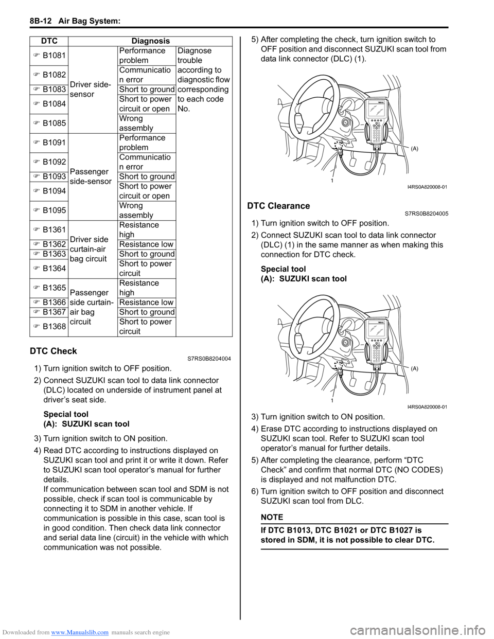
2) Connect SUZUKI scan tool to data link connector (DLC) located on underside of instrument panel at
driver’s seat side.
Special tool
(A): SUZUKI scan tool
3) Turn ignition switch to ON position.
4) Read DTC according to instructions displayed on SUZUKI scan tool and print it or write it down. Refer
to SUZUKI scan tool operator’s manual for further
details.
If communication between scan tool and SDM is not
possible, check if scan tool is communicable by
connecting it to SDM in another vehicle. If
communication is possible in this case, scan tool is
in good condition. Then check data link connector
and serial data line (circuit) in the vehicle with which
communication was not possible. 5) After completing the check,
turn ignition switch to
OFF position and disconnect SUZUKI scan tool from
data link connector (DLC) (1).
DTC ClearanceS7RS0B8204005
1) Turn ignition switch to OFF position.
2) Connect SUZUKI scan tool to data link connector (DLC) (1) in the same manner as when making this
connection for DTC check.
Special tool
(A): SUZUKI scan tool
3) Turn ignition switch to ON position.
4) Erase DTC according to instructions displayed on
SUZUKI scan tool. Refer to SUZUKI scan tool
operator’s manual for further details.
5) After completing the clearance, perform “DTC Check” and confirm that normal DTC (NO CODES)
is displayed and not malfunction DTC.
6) Turn ignition switch to OFF position and disconnect SUZUKI scan tool from DLC.
NOTE
If DTC B1013, DTC B1 021 or DTC B1027 is
stored in SDM, it is not possible to clear DTC.
�) B1081
Driver side-
sensor Performance
problem
Diagnose
trouble
according to
diagnostic flow
corresponding
to each code
No.
�)
B1082 Communicatio
n error
�) B1083 Short to ground
�) B1084 Short to power
circuit or open
�) B1085 Wrong
assembly
�) B1091
Passenger
side-sensor Performance
problem
�) B1092 Communicatio
n error
�) B1093 Short to ground
�) B1094 Short to power
circuit or open
�) B1095 Wrong
assembly
�) B1361
Driver side
curtain-air
bag circuit Resistance
high
�) B1362 Resistance low
�) B1363 Short to ground
�) B1364 Short to power
circuit
�) B1365
Passenger
side curtain-
air bag
circuit Resistance
high
�) B1366 Resistance low
�) B1367 Short to ground
�) B1368 Short to power
circuit
DTC Diagnosis
1
(A)I4RS0A820008-01
1(A)I4RS0A820008-01
Page 1066 of 1496
Downloaded from www.Manualslib.com manuals search engine 8B-28 Air Bag System:
NOTE
Upon completion of inspection and repair work, perform the following items.
• Reconnect all air bag system components and ensure all components are properly mounted.
• Clear DTCs referring to “DTC Clearance”, if any.
• Repeat “Air Bag Diagnostic System Check” to confirm that the trouble has been corrected.
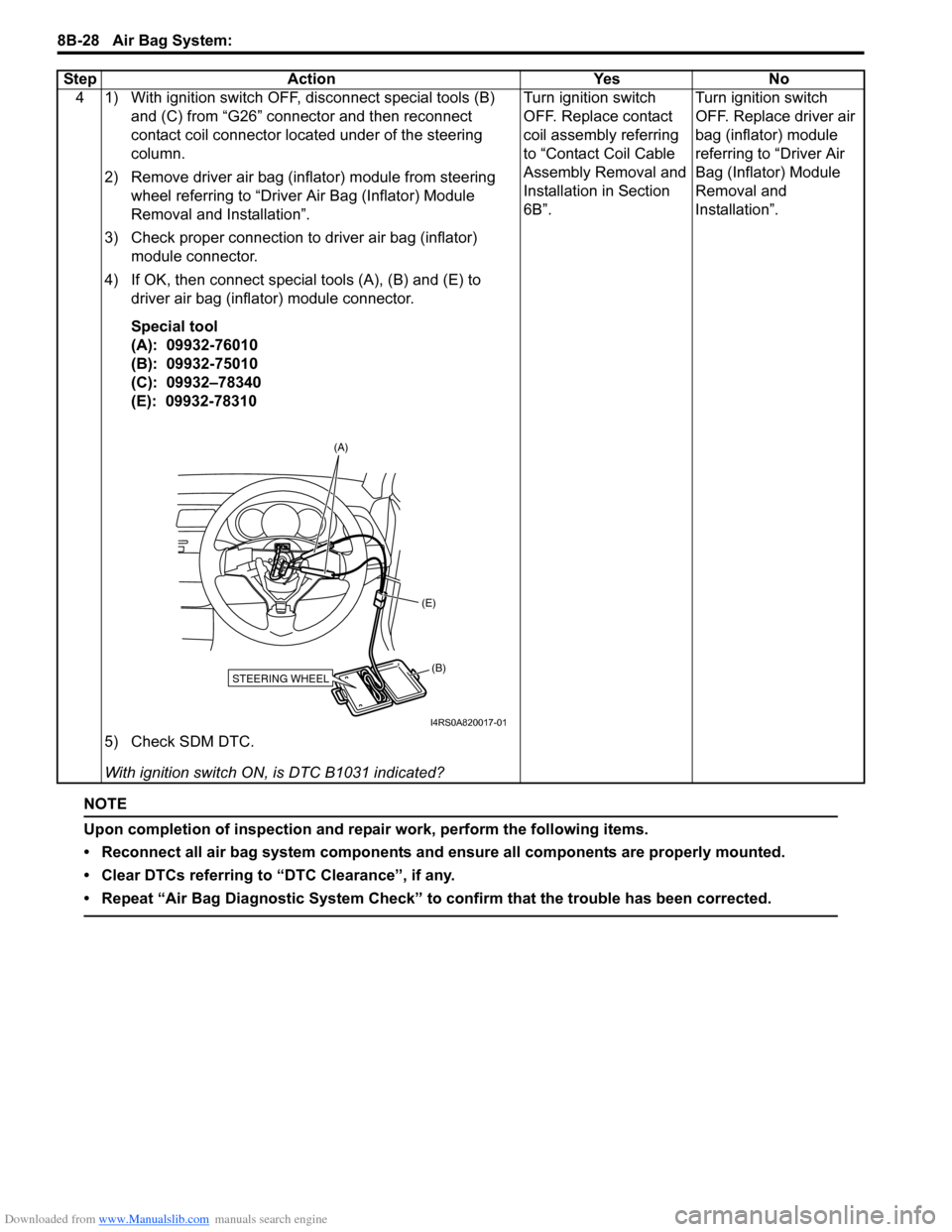
4 1) With ignition switch OFF, disconnect special tools (B) and (C) from “G26” connector and then reconnect
contact coil connector located under of the steering
column.
2) Remove driver air bag (inflator) module from steering wheel referring to “Driver Air Bag (Inflator) Module
Removal and Installation”.
3) Check proper connection to driver air bag (inflator) module connector.
4) If OK, then connect special tools (A), (B) and (E) to driver air bag (inflator) module connector.
Special tool
(A): 09932-76010
(B): 09932-75010
(C): 09932–78340
(E): 09932-78310
5) Check SDM DTC.
With ignition switch ON , is DTC B1031 indicated? Turn ignition switch
OFF. Replace contact
coil assembly referring
to “Contact Coil Cable
Assembly Removal and
Installation in Section
6B”.
Turn ignition switch
OFF. Replace driver air
bag (inflator) module
referring to “Driver Air
Bag (Inflator) Module
Removal and
Installation”.
Step Action Yes No
STEERING WHEEL(B)
(E)
(A)
I4RS0A820017-01
Page 1071 of 1496
Downloaded from www.Manualslib.com manuals search engine Air Bag System: 8B-33
NOTE
Upon completion of inspection and repair work, perform the following items.
• Reconnect all air bag system components and ensure all components are properly mounted.
• Clear DTCs referring to “DTC Clearance”, if any.
• Repeat “Air Bag Diagnostic System Check” to confirm that the trouble has been corrected.
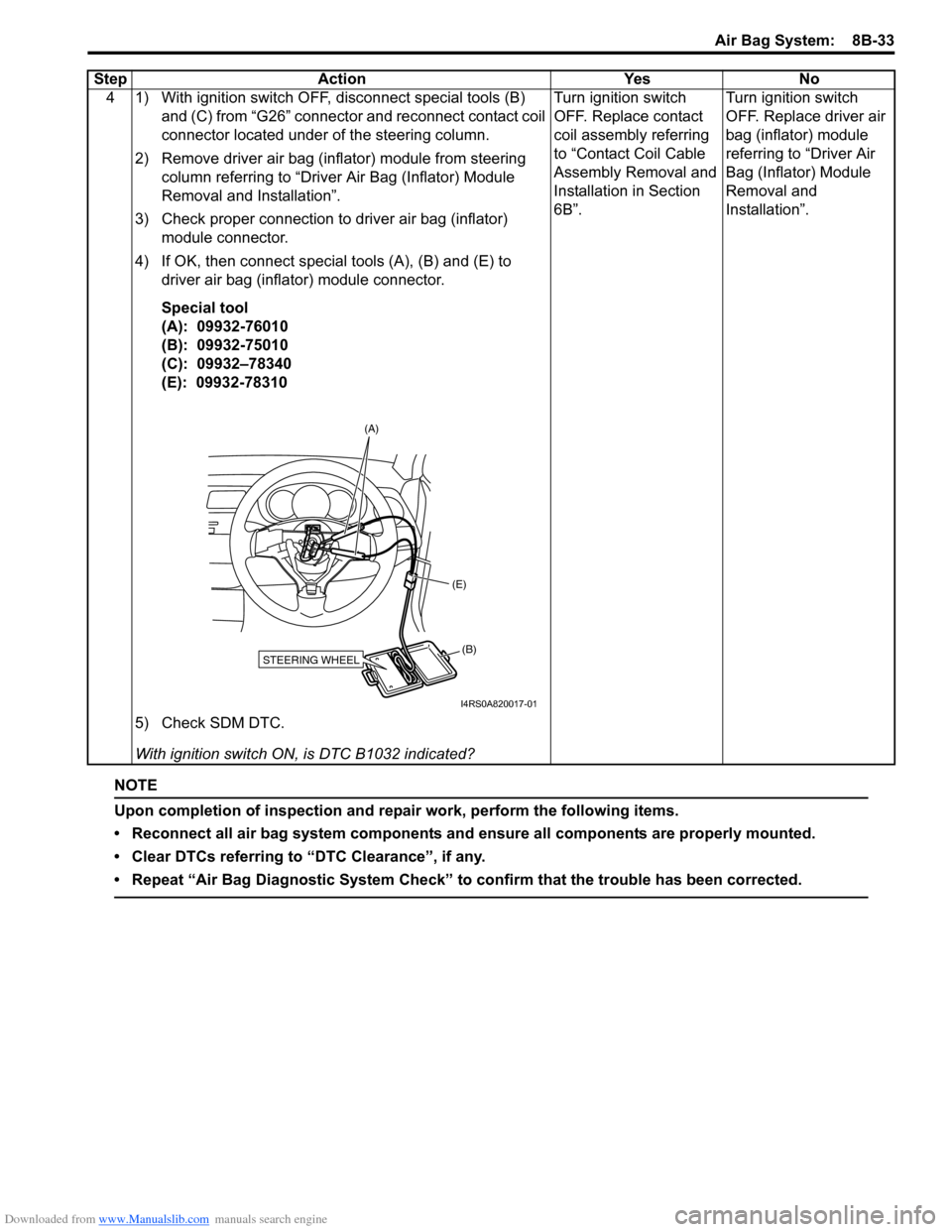
4 1) With ignition switch OFF, disconnect special tools (B) and (C) from “G26” connector and reconnect contact coil
connector located under of the steering column.
2) Remove driver air bag (inflator) module from steering column referring to “Driver Air Bag (Inflator) Module
Removal and Installation”.
3) Check proper connection to driver air bag (inflator) module connector.
4) If OK, then connect special tools (A), (B) and (E) to driver air bag (inflator) module connector.
Special tool
(A): 09932-76010
(B): 09932-75010
(C): 09932–78340
(E): 09932-78310
5) Check SDM DTC.
With ignition switch ON , is DTC B1032 indicated? Turn ignition switch
OFF. Replace contact
coil assembly referring
to “Contact Coil Cable
Assembly Removal and
Installation in Section
6B”.
Turn ignition switch
OFF. Replace driver air
bag (inflator) module
referring to “Driver Air
Bag (Inflator) Module
Removal and
Installation”.
Step Action Yes No
STEERING WHEEL(B)
(E)
(A)
I4RS0A820017-01
Page 1076 of 1496
Downloaded from www.Manualslib.com manuals search engine 8B-38 Air Bag System:
NOTE
Upon completion of inspection and repair work, perform the following items.
• Reconnect all air bag system components and ensure all components are properly mounted.
• Clear DTCs referring to “DTC Clearance”, if any.
• Repeat “Air Bag Diagnostic System Check” to confirm that the trouble has been corrected.
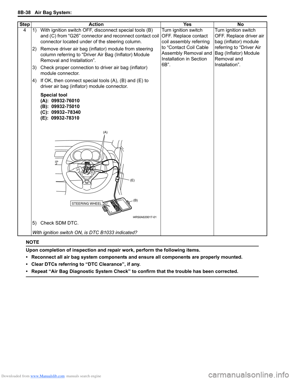
4 1) With ignition switch OFF, disconnect special tools (B) and (C) from “G26” connector and reconnect contact coil
connector located under of the steering column.
2) Remove driver air bag (inflator) module from steering column referring to “Driver Air Bag (Inflator) Module
Removal and Installation”.
3) Check proper connection to driver air bag (inflator) module connector.
4) If OK, then connect special tools (A), (B) and (E) to driver air bag (inflator) module connector.
Special tool
(A): 09932-76010
(B): 09932-75010
(C): 09932–78340
(E): 09932-78310
5) Check SDM DTC.
With ignition switch ON , is DTC B1033 indicated? Turn ignition switch
OFF. Replace contact
coil assembly referring
to “Contact Coil Cable
Assembly Removal and
Installation in Section
6B”.
Turn ignition switch
OFF. Replace driver air
bag (inflator) module
referring to “Driver Air
Bag (Inflator) Module
Removal and
Installation”.
Step Action Yes No
STEERING WHEEL(B)
(E)
(A)
I4RS0A820017-01
Page 1081 of 1496
Downloaded from www.Manualslib.com manuals search engine Air Bag System: 8B-43
NOTE
Upon completion of inspection and repair work, perform the following items.
• Reconnect all air bag system components and ensure all components are properly mounted.
• Clear DTCs referring to “DTC Clearance”, if any.
• Repeat “Air Bag Diagnostic System Check” to confirm that the trouble has been corrected.
4 1) With ignition switch OFF, disconnect special tools (B) and (C) from “G26” connector and reconnect contact coil
connector located under of the steering column.
2) Remove driver air bag (inflator) module from steering column referring to “Driver Air Bag (Inflator) Module
Removal and Installation”.
3) Check proper connection to driver air bag (inflator) module connector.
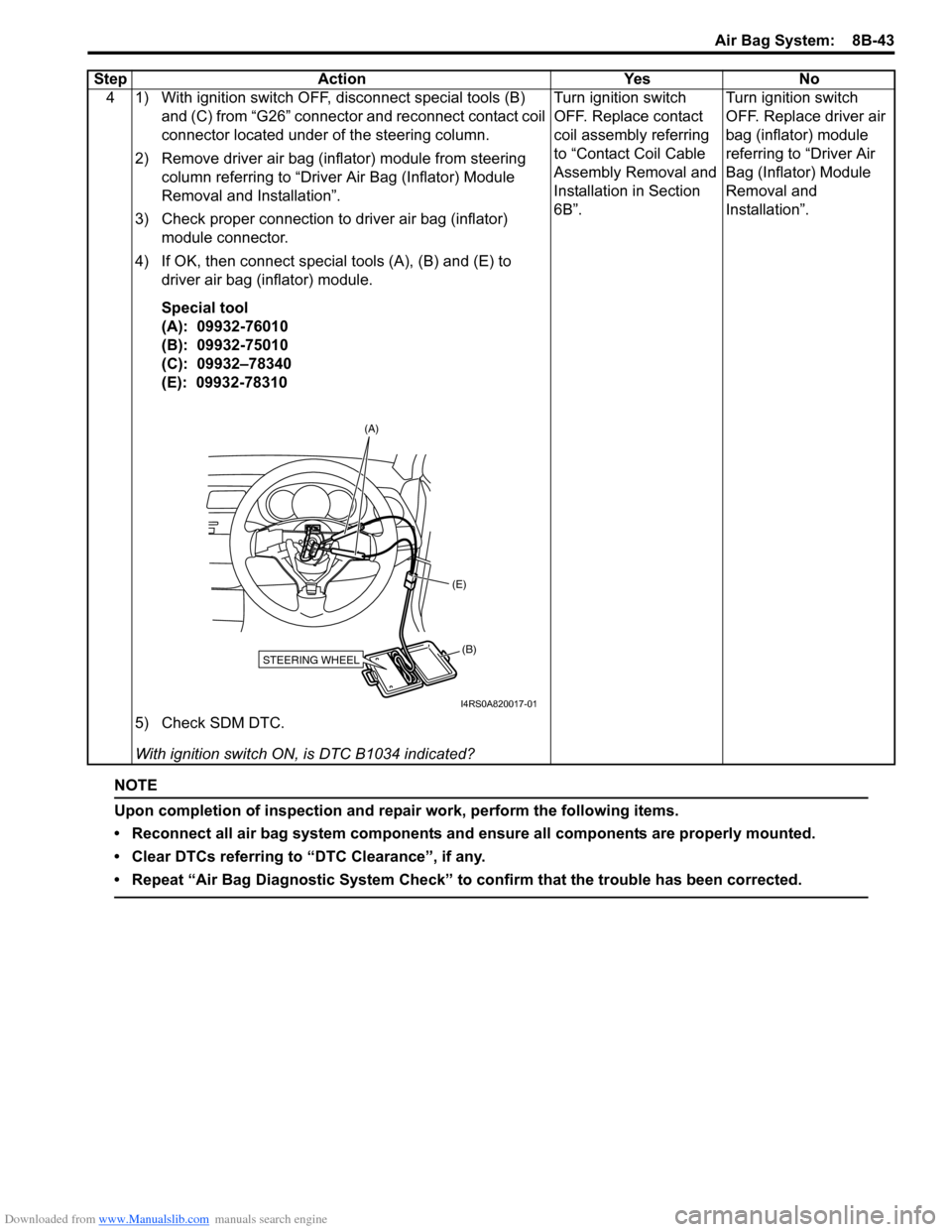
4) If OK, then connect special tools (A), (B) and (E) to driver air bag (inflator) module.
Special tool
(A): 09932-76010
(B): 09932-75010
(C): 09932–78340
(E): 09932-78310
5) Check SDM DTC.
With ignition switch ON , is DTC B1034 indicated? Turn ignition switch
OFF. Replace contact
coil assembly referring
to “Contact Coil Cable
Assembly Removal and
Installation in Section
6B”.
Turn ignition switch
OFF. Replace driver air
bag (inflator) module
referring to “Driver Air
Bag (Inflator) Module
Removal and
Installation”.
Step Action Yes No
STEERING WHEEL(B)
(E)
(A)
I4RS0A820017-01
Page 1131 of 1496
Downloaded from www.Manualslib.com manuals search engine Air Bag System: 8B-93
Contact Coil Cable and Its Circuit CheckS7RS0B8204047
TroubleshootingStep Action Yes No 1 Driver air bag circuit check
1) Remove driver air bag (inflator) module referring to
“Driver Air Bag (Inflator) Module Removal and
Installation”.
2) With ignition switch turned OFF, disconnect SDM connector “L29”.
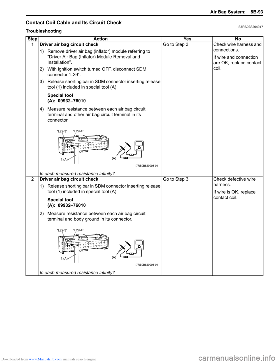
3) Release shorting bar in SDM connector inserting release tool (1) included in special tool (A).
Special tool
(A): 09932–76010
4) Measure resistance between each air bag circuit terminal and other air bag circuit terminal in its
connector.
Is each measured resistance infinity? Go to Step 3. Check wire harness and
connections.
If wire and connection
are OK, replace contact
coil.
2 Driver air bag circuit check
1) Release shorting bar in SDM connector inserting release
tool (1) included in special tool (A).
Special tool
(A): 09932–76010
2) Measure resistance between each air bag circuit terminal and body ground in its connector.
Is each measured resistance infinity? Go to Step 3. Check defective wire
harness.
If wire is OK, replace
contact coil.
“L29-4”
“L29-3”
1,(A)(A)
I7RS0B820003-01
“L29-4”
“L29-3”
1,(A)(A)
I7RS0B820003-01
Page 1132 of 1496
Downloaded from www.Manualslib.com manuals search engine 8B-94 Air Bag System:
3Contact coil circuit (driver air bag circuit) check
1) Remove contact coil referr ing to “Contact Coil Cable
Assembly Removal and Inst allation in Section 6B”.
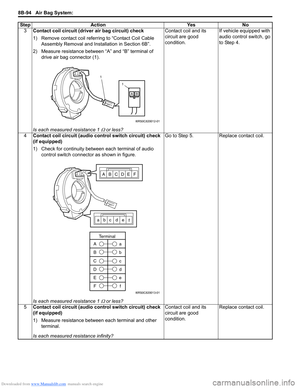
2) Measure resistance between “A” and “B” terminal of drive air bag connector (1).
Is each measured resistance 1
Ω or less? Contact coil and its
circuit are good
condition.
If vehicle equipped with
audio control switch, go
to Step 4.
4 Contact coil circuit (audio control switch circuit) check
(if equipped)
1) Check for continuity between each terminal of audio
control switch connector as shown in figure.
Is each measured resistance 1
Ω or less? Go to Step 5. Replace contact coil.
5 Contact coil circuit (audio control switch circuit) check
(if equipped)
1) Measure resistance between each terminal and other
terminal.
Is each measured resistance infinity? Contact coil and its
circuit are good
condition.
Replace contact coil.
Step Action Yes No
1
1
AB
I6RS0C820012-01
ABCDEF
abc de
f
A
Ba
b
C
D c
d
E F e
f
Terminal
I6RS0C820013-01
Page 1136 of 1496
Downloaded from www.Manualslib.com manuals search engine 8B-98 Air Bag System:
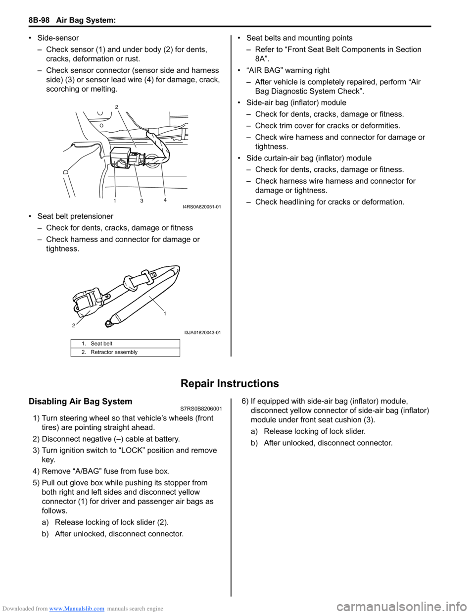
• Side-sensor– Check sensor (1) and under body (2) for dents, cracks, deformation or rust.
– Check sensor connector (sensor side and harness side) (3) or sensor lead wire (4) for damage, crack,
scorching or melting.
• Seat belt pretensioner – Check for dents, cracks , damage or fitness
– Check harness and connector for damage or tightness. • Seat belts and mounting points
– Refer to “Front Seat Belt Components in Section 8A”.
• “AIR BAG” warning right
– After vehicle is completely repaired, perform “Air Bag Diagnostic System Check”.
• Side-air bag (inflator) module – Check for dents, cra cks, damage or fitness.
– Check trim cover for cracks or deformities.
– Check wire harness and connector for damage or tightness.
• Side curtain-air bag (inflator) module – Check for dents, cra cks, damage or fitness.
– Check harness wire harness and connector for damage or tightness.
– Check headlining for cracks or deformation.
Repair Instructions
Disabling Air Bag SystemS7RS0B8206001
1) Turn steering wheel so that vehicle’s wheels (front tires) are pointing straight ahead.
2) Disconnect negative (–) cable at battery.
3) Turn ignition switch to “LOCK” position and remove key.
4) Remove “A/BAG” fu se from fuse box.
5) Pull out glove box while pushing its stopper from
both right and left sides and disconnect yellow
connector (1) for driver and passenger air bags as
follows.
a) Release locking of lock slider (2).
b) After unlocked, disconnect connector. 6) If equipped with side-air bag (inflator) module,
disconnect yellow connector of side-air bag (inflator)
module under front seat cushion (3).
a) Release locking of lock slider.
b) After unlocked, disconnect connector.
1. Seat belt
2. Retractor assembly
13 4
2I4RS0A820051-01
I3JA01820043-01