2006 SUZUKI SWIFT hose
[x] Cancel search: hosePage 1370 of 1496
Downloaded from www.Manualslib.com manuals search engine 9J-1 Hood / Fenders / Doors:
Body, Cab and Accessories
Hood / Fenders / Doors
Repair Instructions
Hood Removal and InstallationS7RS0B9A06001
Removal
CAUTION!
Place cloth to prevent body from any
damage.
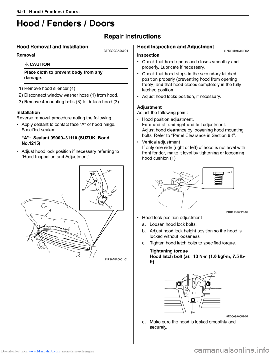
1) Remove hood silencer (4).
2) Disconnect window washer hose (1) from hood.
3) Remove 4 mounting bolts (3) to detach hood (2).
Installation
Reverse removal procedure noting the following.
• Apply sealant to contact face “A” of hood hinge. Specified sealant.
“A”: Sealant 99000–31110 (SUZUKI Bond
No.1215)
• Adjust hood lock position if necessary referring to “Hood Inspection and Adjustment”.
Hood Inspection and AdjustmentS7RS0B9A06002
Inspection
• Check that hood opens and closes smoothly and properly. Lubricate if necessary.
• Check that hood stops in the secondary latched position properly (preventing hood from opening
freely) and that hood closes completely in the fully
latched position.
• Adjust hood locks position, if necessary.
Adjustment
Adjust the following point:
• Hood position adjustment. Fore-and-aft and right-and-left adjustment.
Adjust hood clearance by loosening hood mounting
bolts. Refer to “Panel Clearance in Section 9K”.
• Vertical adjustment If only one side (right or left) of hood is not level with
front fender, make it level by tightening or loosening
hood cushion (1).
• Hood lock position adjustment a. Loosen hood lock bolts.
b. Adjust hood lock height position so the hood is locked without looseness.
c. Tighten hood latch bolts to specified torque.
Tightening torque
Hood latch bolt (a): 10 N·m (1.0 kgf-m, 7.5 lb-
ft)
d. Make sure the hood is locked smoothly and securely.
“A”
“A”
3
2
4
1
I4RS0A9A0001-01
I2RH019A0022-01
(a)
(a)I4RS0A9A0002-01
Page 1375 of 1496
Downloaded from www.Manualslib.com manuals search engine Hood / Fenders / Doors: 9J-6
Rear End Door Assembly ComponentsS7RS0B9A06009
Rear End Door Assembly Removal and
Installation
S7RS0B9A06010
WARNING!
Be careful enough when you open and shut
with door balancer has not adhered to Rear
end door.
Otherwise, Rear end door doses in weight
and is injured.
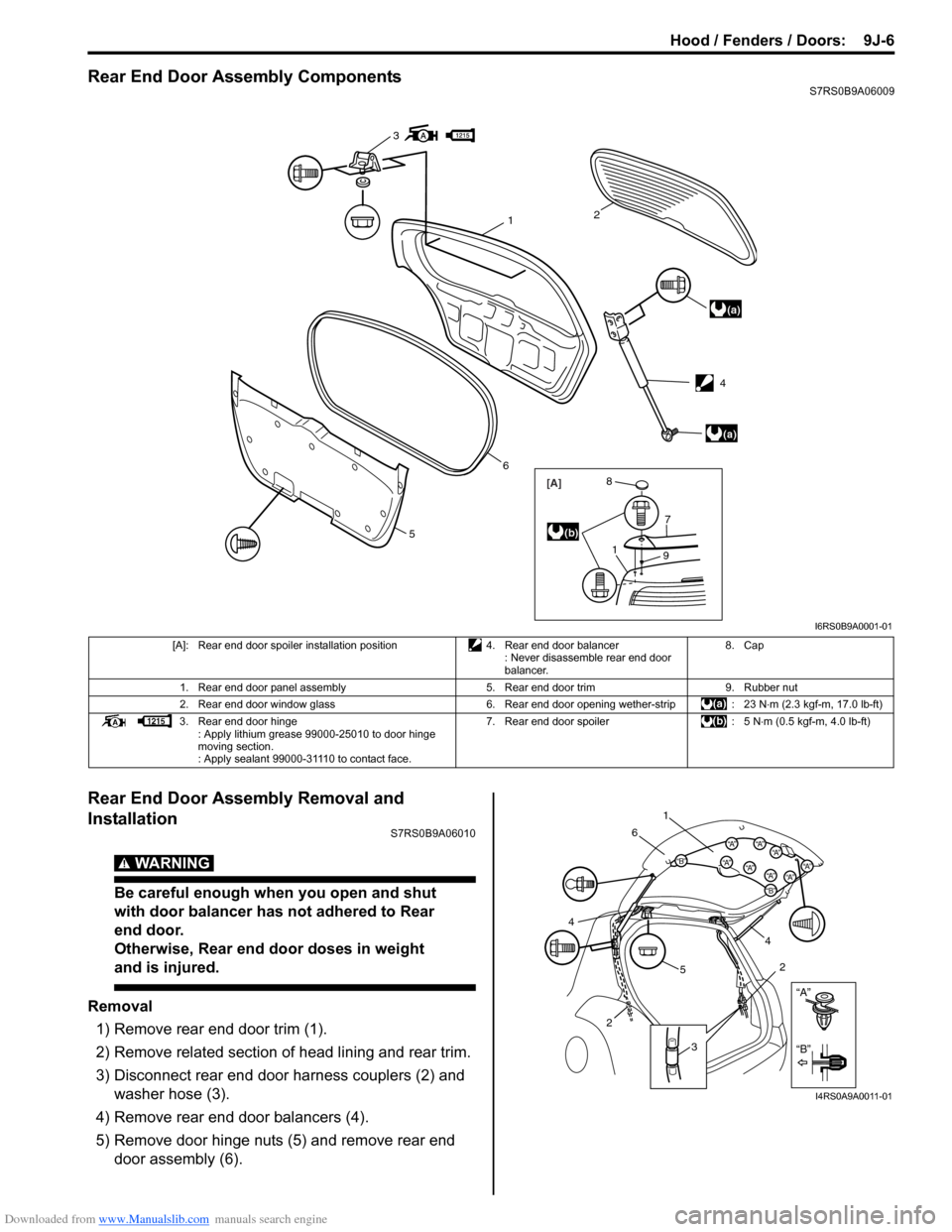
Removal1) Remove rear end door trim (1).
2) Remove related section of head lining and rear trim.
3) Disconnect rear end door harness couplers (2) and washer hose (3).
4) Remove rear end door balancers (4).
5) Remove door hinge nuts (5) and remove rear end door assembly (6).
3
(a)
(a)
12
6
5
[A]
1
7
9
8
(b)
4
I6RS0B9A0001-01
[A]: Rear end door spoiler installation position 4. Rear end door balancer
: Never disassemble rear end door
balancer. 8. Cap
1. Rear end door panel assembly 5. Rear end door trim9. Rubber nut
2. Rear end door window glass 6. Rear end door opening wether-strip: 23 N⋅m (2.3 kgf-m, 17.0 lb-ft)
3. Rear end door hinge : Apply lithium grease 99000-25010 to door hinge
moving section.
: Apply sealant 99000-31110 to contact face. 7. Rear end door spoiler
: 5 N⋅m (0.5 kgf-m, 4.0 lb-ft)
“A”
“B”
“B”
“A”“B”“A”“A”“A”
“A”“A”“A”
“A”
1
6
5 4
2
3
2
4
I4RS0A9A0011-01
Page 1406 of 1496
Downloaded from www.Manualslib.com manuals search engine 10B-3 Body Electrical Control System:
Theft Deterrent LightS7RS0BA201003
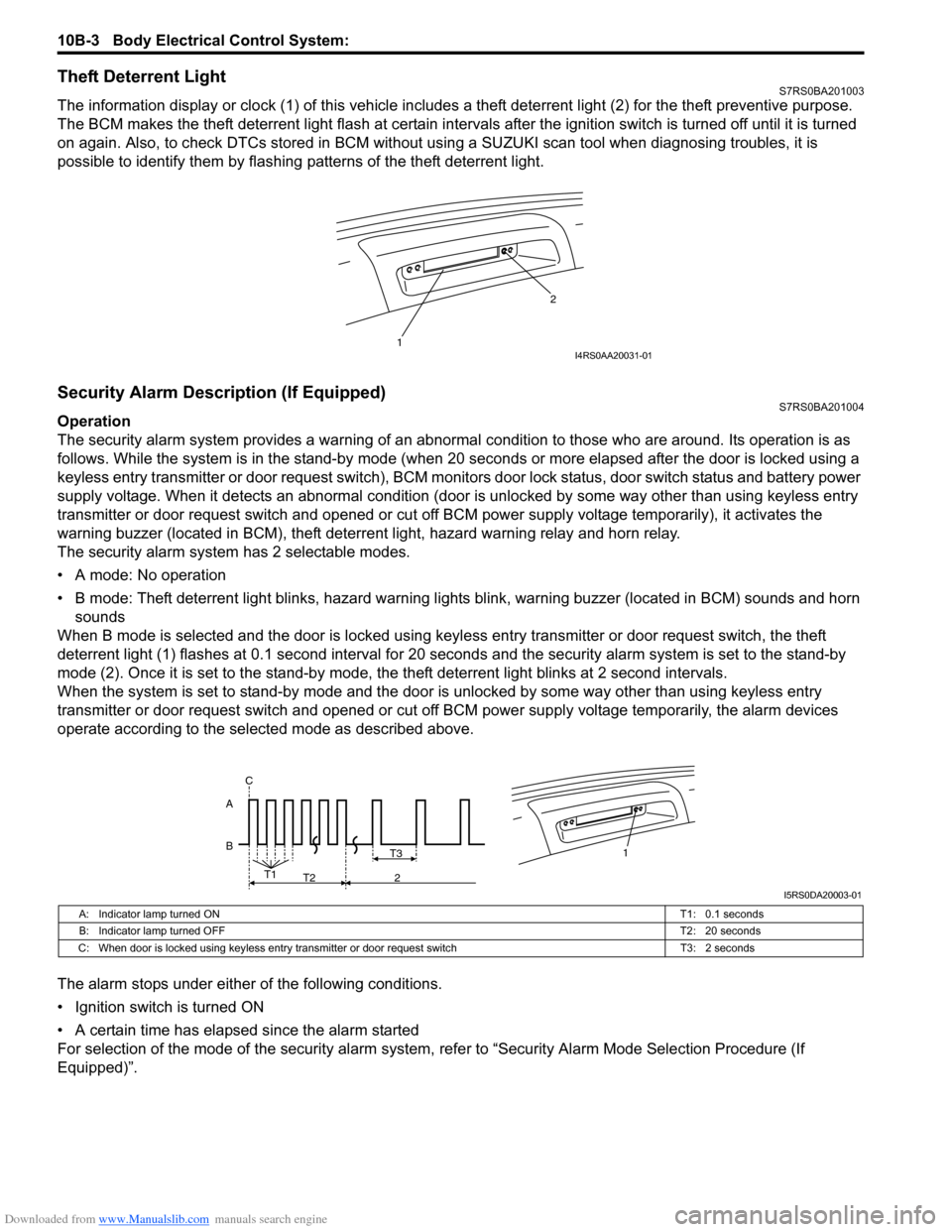
The information display or clock (1) of this vehicle includes a theft deterrent light (2) for the theft preventive purpose.
The BCM makes the theft deterrent light flash at certain interval s after the ignition switch is turned off until it is turned
on again. Also, to check DTCs stored in BCM without usin g a SUZUKI scan tool when diagnosing troubles, it is
possible to identify them by flashing patterns of the theft deterrent light.
Security Alarm Description (If Equipped)S7RS0BA201004
Operation
The security alarm system provides a warning of an abnormal condition to those who are around. Its operation is as
follows. While the system is in the stand- by mode (when 20 seconds or more elapsed after the door is locked using a
keyless entry transmitter or door request switch), BCM monitors door lock status, door switch status and battery power
supply voltage. When it detects an abnormal condition (door is unlocked by some way other than using keyless entry
transmitter or door request switch and opened or cut off BCM power supply voltage temporarily), it activates the
warning buzzer (located in BCM), theft deterr ent light, hazard warning relay and horn relay.
The security alarm system has 2 selectable modes.
• A mode: No operation
• B mode: Theft deterrent light blinks, hazard warning lights blink, warning buzzer (located in BCM) sounds and horn
sounds
When B mode is selected and the door is locked using keyl ess entry transmitter or door request switch, the theft
deterrent light (1) flashes at 0.1 second interval for 20 seconds and the se curity alarm system is set to the stand-by
mode (2). Once it is se t to the stand-by mode, the theft deterrent light blinks at 2 second intervals.
When the system is set to stand-by mode and the door is unlocked by some way other than using keyless entry
transmitter or door request switch and opened or cut off BCM power supply voltage temporarily, the alarm devices
operate according to the selected mode as described above.
The alarm stops under either of the following conditions.
• Ignition switch is turned ON
• A certain time has elapsed since the alarm started
For selection of the mode of the security alarm system , refer to “Security Alarm Mode Selection Procedure (If
Equipped)”.
1 2I4RS0AA20031-01
B A1T3
T1
T2 2
C
I5RS0DA20003-01
A: Indicator lamp turned ON
T1: 0.1 seconds
B: Indicator lamp turned OFF T2: 20 seconds
C: When door is locked using keyless entry tr ansmitter or door request switch T3: 2 seconds
Page 1426 of 1496
Downloaded from www.Manualslib.com manuals search engine 10B-23 Body Electrical Control System:
DTC TroubleshootingStep Action YesNo
1 DTC check of BCM
Is DTC U0155 (No. 0155) and DTC U1073 (No. 1073)
detected together? Go to “DTC U1073 (No.
1073): Control Module
Communication Bus
Off”.Go to Step 2.
2 Control module connector check
1) Check connection of connectors of all control modules
communicating by means of CAN.
2) Recheck BCM for DTC.
Is DTC U0155 (No. 0155) detected? Go to Step 3.
Intermittent trouble.
Check for intermittent
referring to “Intermittent
and Poor Connection
Inspection in Section
00”.
3 Combination meter power and ground circuit check
1) Turn ignition switch to ON position.
Do warning lights in combi nation meter other than key
indicator light light up? Go to Step 4.
Check combination
meter power and
ground circuit. If circuit
is OK, substitute a
known-good
combination meter and
recheck.
4 CAN communication circuit check
1) Turn ignition switch to OFF position.
2) Disconnect connectors from BCM, combination meter
and steering angle sensor (ESP ® model).
3) Check CAN communication circuit between BCM and combination meter for open, short and high resistance.
Is each CAN communication circuit in good condition? Go to Step 5.
Repair circuit.
5 CAN communication circuit check
1) Disconnect connectors of all control modules
communicating by means of CAN.
2) Check CAN communication circuit between control modules other than Step 4 for open, short and high
resistance.
Is each CAN communication circuit in good condition? Go to Step 6.
Repair circuit.
6 DTC check of BCM
1) Connect connectors of disconnected control modules
communicating by means of CAN.
2) Disconnect connector of any one of control module other than BCM.
3) Recheck BCM for DTC.
Is DTC U0155 (No.0155) detected? Disconnect connectors
of control modules other
than the one whose
connector is
disconnected in Step 2)
one by one and check
that DTC U0155 is
detected by BCM each
time connector is
disconnected. When
DTC U0155 is not
detected by BCM while
checking in this way, go
to description under
“NO” below. If DTC
U0155 is detected by
BCM even when
connectors of all control
modules that use CAN
communication with
BCM are disconnected,
substitute a known-
good BCM and recheck.Check power and
ground circuit of control
module disconnected in
Step 2). If circuit is OK,
substitute a known-
good control module
disconnected in Step 2)
and recheck.
Page 1428 of 1496
Downloaded from www.Manualslib.com manuals search engine 10B-25 Body Electrical Control System:
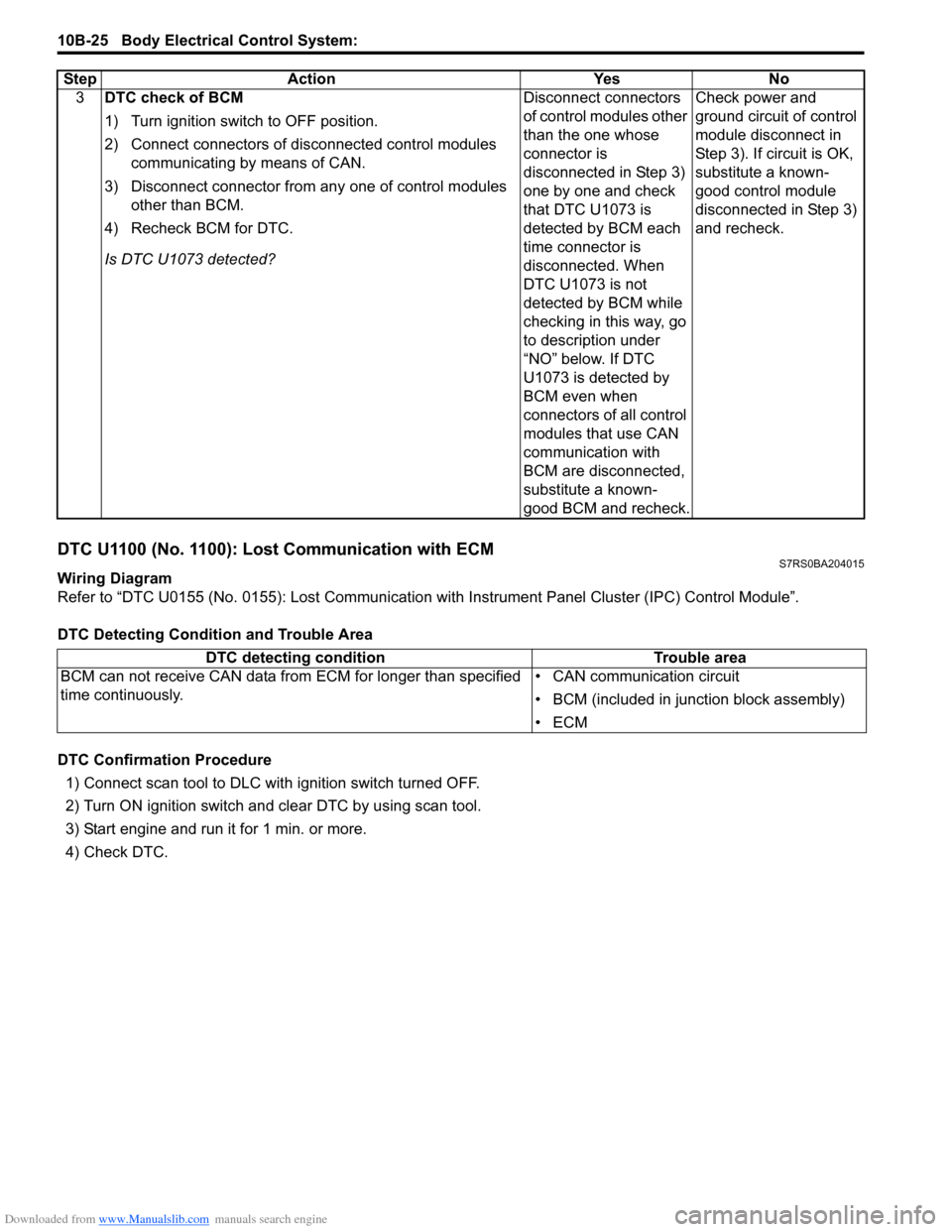
DTC U1100 (No. 1100): Lost Communication with ECMS7RS0BA204015
Wiring Diagram
Refer to “DTC U0155 (No. 0155): Lost Communication with Instrument Panel Cluster (IPC) Control Module”.
DTC Detecting Condition and Trouble Area
DTC Confirmation Procedure 1) Connect scan tool to DLC with ignition switch turned OFF.
2) Turn ON ignition switch and clear DTC by using scan tool.
3) Start engine and run it for 1 min. or more.
4) Check DTC. 3
DTC check of BCM
1) Turn ignition switch to OFF position.
2) Connect connectors of disconnected control modules
communicating by means of CAN.
3) Disconnect connector from any one of control modules other than BCM.
4) Recheck BCM for DTC.
Is DTC U1073 detected? Disconnect connectors
of control modules other
than the one whose
connector is
disconnected in Step 3)
one by one and check
that DTC U1073 is
detected by BCM each
time connector is
disconnected. When
DTC U1073 is not
detected by BCM while
checking in this way, go
to description under
“NO” below. If DTC
U1073 is detected by
BCM even when
connectors of all control
modules that use CAN
communication with
BCM are disconnected,
substitute a known-
good BCM and recheck.Check power and
ground circuit of control
module disconnect in
Step 3). If circuit is OK,
substitute a known-
good control module
disconnected in Step 3)
and recheck.
Step Action Yes No
DTC detecting condition
Trouble area
BCM can not receive CAN data from ECM for longer than specified
time continuously. • CAN communication circuit
• BCM (included in junction block assembly)
•ECM
Page 1430 of 1496
Downloaded from www.Manualslib.com manuals search engine 10B-27 Body Electrical Control System:
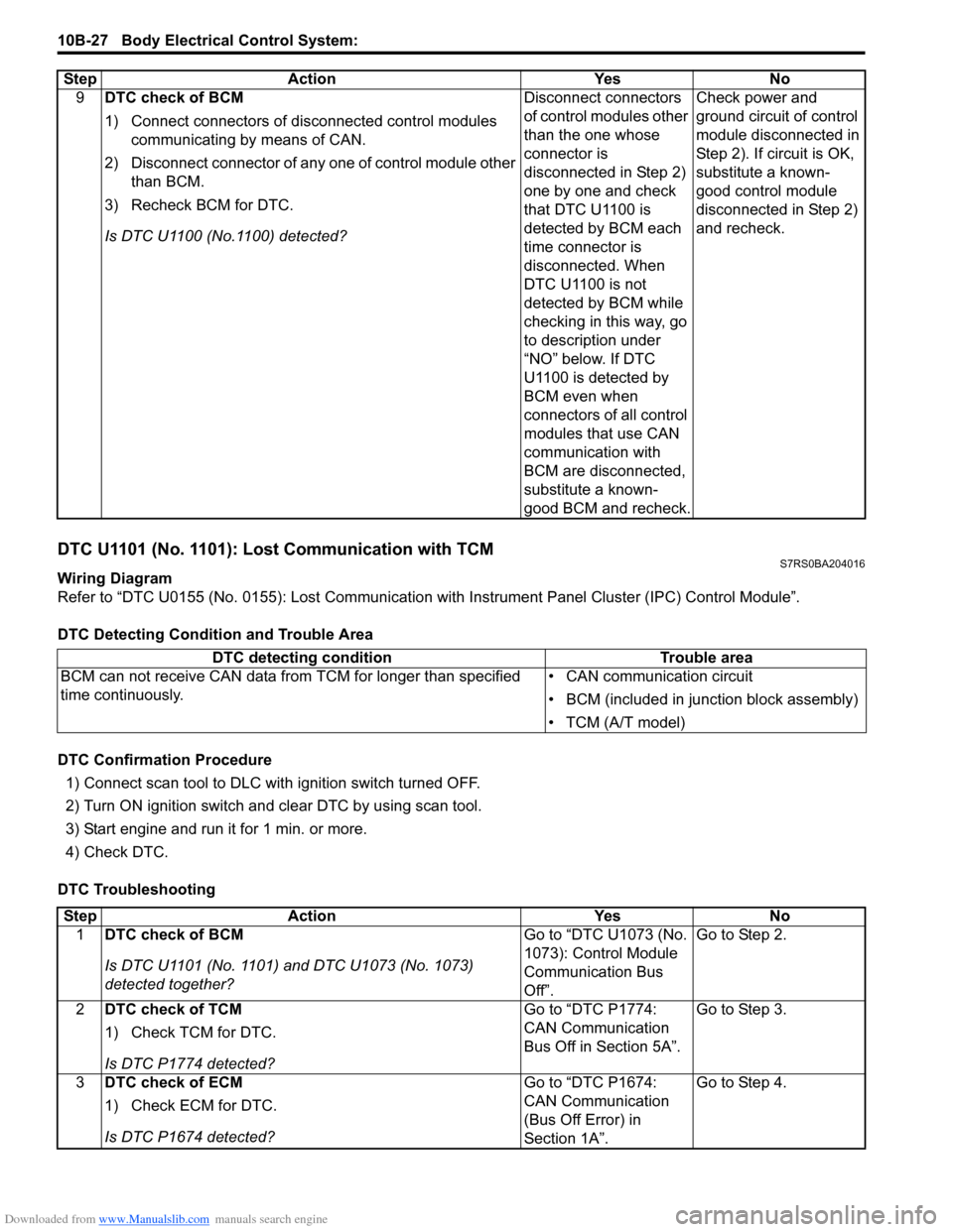
DTC U1101 (No. 1101): Lost Communication with TCMS7RS0BA204016
Wiring Diagram
Refer to “DTC U0155 (No. 0155): Lost Communication with Instrument Panel Cluster (IPC) Control Module”.
DTC Detecting Condition and Trouble Area
DTC Confirmation Procedure 1) Connect scan tool to DLC with ignition switch turned OFF.
2) Turn ON ignition switch and clear DTC by using scan tool.
3) Start engine and run it for 1 min. or more.
4) Check DTC.
DTC Troubleshooting 9
DTC check of BCM
1) Connect connectors of disconnected control modules
communicating by means of CAN.
2) Disconnect connector of any one of control module other than BCM.
3) Recheck BCM for DTC.
Is DTC U1100 (No.1100) detected? Disconnect connectors
of control modules other
than the one whose
connector is
disconnected in Step 2)
one by one and check
that DTC U1100 is
detected by BCM each
time connector is
disconnected. When
DTC U1100 is not
detected by BCM while
checking in this way, go
to description under
“NO” below. If DTC
U1100 is detected by
BCM even when
connectors of all control
modules that use CAN
communication with
BCM are disconnected,
substitute a known-
good BCM and recheck.Check power and
ground circuit of control
module disconnected in
Step 2). If circuit is OK,
substitute a known-
good control module
disconnected in Step 2)
and recheck.
Step Action Yes No
DTC detecting condition
Trouble area
BCM can not receive CAN data from TCM for longer than specified
time continuously. • CAN communication circuit
• BCM (included in junction block assembly)
• TCM (A/T model)
Step
Action YesNo
1 DTC check of BCM
Is DTC U1101 (No. 1101) and DTC U1073 (No. 1073)
detected together? Go to “DTC U1073 (No.
1073): Control Module
Communication Bus
Off”.Go to Step 2.
2 DTC check of TCM
1) Check TCM for DTC.
Is DTC P1774 detected? Go to “DTC P1774:
CAN Communication
Bus Off in Section 5A”.
Go to Step 3.
3 DTC check of ECM
1) Check ECM for DTC.
Is DTC P1674 detected? Go to “DTC P1674:
CAN Communication
(Bus Off Error) in
Section 1A”.Go to Step 4.
Page 1431 of 1496
Downloaded from www.Manualslib.com manuals search engine Body Electrical Control System: 10B-28
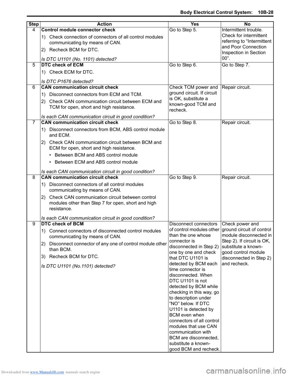
4Control module connector check
1) Check connection of connectors of all control modules
communicating by means of CAN.
2) Recheck BCM for DTC.
Is DTC U1101 (No. 1101) detected? Go to Step 5. Intermittent trouble.
Check for intermittent
referring to “Intermittent
and Poor Connection
Inspection in Section
00”.
5 DTC check of ECM
1) Check ECM for DTC.
Is DTC P1676 detected? Go to Step 6. Go to Step 7.
6 CAN communication circuit check
1) Disconnect connectors from ECM and TCM.
2) Check CAN communication circuit between ECM and
TCM for open, short and high resistance.
Is each CAN communication circuit in good condition? Check TCM power and
ground circuit. If circuit
is OK, substitute a
known-good TCM and
recheck.
Repair circuit.
7 CAN communication circuit check
1) Disconnect connectors from BCM, ABS control module
and ECM.
2) Check CAN communication circuit between BCM and ECM for open, short and high resistance.
• Between BCM and ABS control module
• Between ECM and ABS control module
Is each CAN communication circuit in good condition? Go to Step 8. Repair circuit.
8 CAN communication circuit check
1) Disconnect connectors of all control modules
communicating by means of CAN.
2) Check CAN communication circuit between control modules other than Step 7 for open, short and high
resistance.
Is each CAN communication circuit in good condition? Go to Step 9. Repair circuit.
9 DTC check of BCM
1) Connect connectors of disconnected control modules
communicating by means of CAN.
2) Disconnect connector of any one of control module other than BCM.
3) Recheck BCM for DTC.
Is DTC U1101 (No.1101) detected? Disconnect connectors
of control modules other
than the one whose
connector is
disconnected in Step 2)
one by one and check
that DTC U1101 is
detected by BCM each
time connector is
disconnected. When
DTC U1101 is not
detected by BCM while
checking in this way, go
to description under
“NO” below. If DTC
U1101 is detected by
BCM even when
connectors of all control
modules that use CAN
communication with
BCM are disconnected,
substitute a known-
good BCM and recheck.Check power and
ground circuit of control
module disconnected in
Step 2). If circuit is OK,
substitute a known-
good control module
disconnected in Step 2)
and recheck.
Step Action Yes No
Page 1433 of 1496
Downloaded from www.Manualslib.com manuals search engine Body Electrical Control System: 10B-30
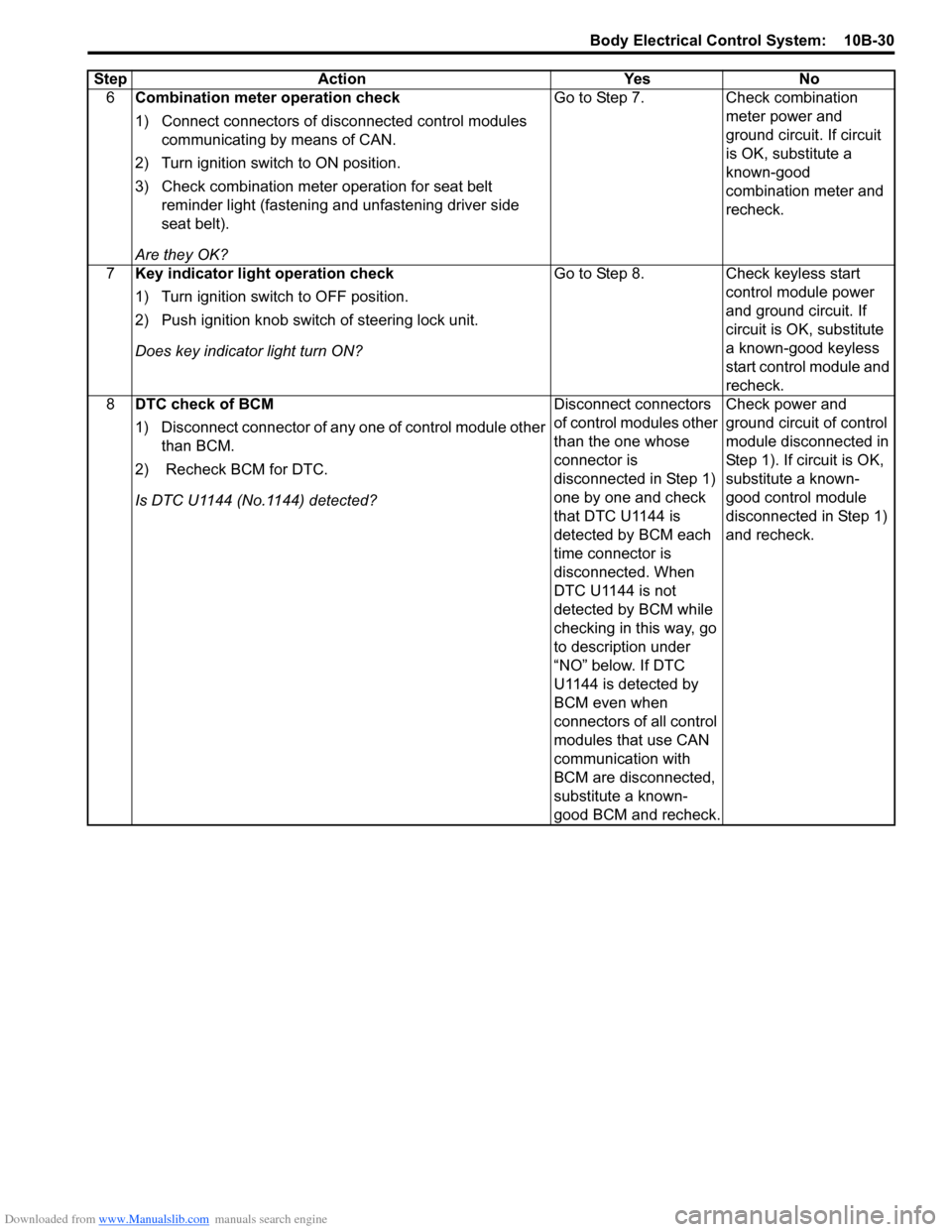
6Combination meter operation check
1) Connect connectors of disconnected control modules
communicating by means of CAN.
2) Turn ignition switch to ON position.
3) Check combination meter operation for seat belt reminder light (fastening and unfastening driver side
seat belt).
Are they OK? Go to Step 7.
Check combination
meter power and
ground circuit. If circuit
is OK, substitute a
known-good
combination meter and
recheck.
7 Key indicator light operation check
1) Turn ignition switch to OFF position.
2) Push ignition knob switch of steering lock unit.
Does key indicator light turn ON? Go to Step 8.
Check keyless start
control module power
and ground circuit. If
circuit is OK, substitute
a known-good keyless
start control module and
recheck.
8 DTC check of BCM
1) Disconnect connector of any one of control module other
than BCM.
2) Recheck BCM for DTC.
Is DTC U1144 (No.1144) detected? Disconnect connectors
of control modules other
than the one whose
connector is
disconnected in Step 1)
one by one and check
that DTC U1144 is
detected by BCM each
time connector is
disconnected. When
DTC U1144 is not
detected by BCM while
checking in this way, go
to description under
“NO” below. If DTC
U1144 is detected by
BCM even when
connectors of all control
modules that use CAN
communication with
BCM are disconnected,
substitute a known-
good BCM and recheck.Check power and
ground circuit of control
module disconnected in
Step 1). If circuit is OK,
substitute a known-
good control module
disconnected in Step 1)
and recheck.
Step
Action YesNo