2006 SUZUKI SWIFT washers
[x] Cancel search: washersPage 645 of 1496
Downloaded from www.Manualslib.com manuals search engine Automatic Transmission/Transaxle: 5A-1
Transmission / Transaxle
Automatic Transmission/Transaxle
Precautions
Precautions in Diagnosing TroubleS7RS0B5100001
• Do not disconnect couplers from TCM, battery cable from battery, TCM ground wire harness from engine or
main fuse before checking the diagnostic information
(DTC, freeze frame data, etc.) stored in TCM memory.
Such disconnection will clea r memorized information
in TCM memory.
• Diagnostic information stored in TCM memory can be cleared as well as checked by using SUZUKI scan
tool or generic scan tool. Before using scan tool, read
its Operator’s (Instruction) Manual carefully to have
good understanding as to what functions are available
and how to use it.
It is indistinguishable wh ich module turns on MIL
because not only ECM but also TCM turns on MIL.
Therefore, check both ECM and TCM for DTC when
MIL lights on.
When checking TCM for DTC, keep in mind that DTC
is displayed on the scan tool as follows depending on
the scan tool used.
– SUZUKI scan tool displays DTC detected by TCM.
– Generic scan tool displays DTC detected by each of ECM and TCM simultaneously.
• Using SUZUKI scan tool the diagnostic information stored in TCM memory can be checked and cleared
as well. Before its use, be sure to read Operator’s
Manual supplied with it carefully to have good
understanding of its functions and usage.
• Be sure to read “Precautions for Electrical Circuit Service in Section 00” befo re inspection and observe
what is written there.
• TCM replacement
– When substituting a known-good TCM, check that all relays and actuators have resistance of
specified value.
Neglecting this check may result in damage to good
TCM.
• Communication of ECUs , ECM, TCM, ABS control
module, keyless start control module and BCM is
established by CAN (Controller Area Network).
Therefore, handle CAN communication line with care
referring to “Precaution for CAN Communication
System in Section 00”.
Precautions for Disassembly and ReassemblyS7RS0B5100002
When repairing automatic transaxle, it is necessary to
conduct the on-vehicle test to investigate where the
cause of the trouble lies first.
Then whether overhaul should be done or not is
determined. If the transaxle is disassembled without
such preliminary procedure, not only the cause of the
trouble would be unknown, but also a secondary trouble
may occur and often time would be wasted.
As the automatic transaxle consists of high precision
component, the following cautions should be strictly
observed when handling its parts in disassembly and
reassembly.
• Disassembling valve body assembly is prohibited
essentially. However, a few parts can be
disassembled. When disassembling valve body
component parts, confirm whether their parts are
allowed to disassemble or not referring to “Valve Body
Assembly Disassembly and Reassembly”.
• When component part of forward clutch, direct clutch, 2nd brake and/or O/D and 2nd coast brake, namely
clutch disc, brake disc, retaining plate and/or
separator plate, have been replaced, all learned
contents, which have been stored in TCM memory by
executing learning control, should be initialized
referring to “Learning Control Initialization”.
• Make sure to wash dirt off from the transaxle so that no such dirt will enter the transaxle during
dismounting and remounting.
• Select a clean place free from dust and dirt for overhauling.
• Place a rubber mat on the work bench to protect parts from damage.
• Work gloves or shop cloth should not be used. (Use a nylon cloth or a paper towel.)
• When separating the case joint, do not pry with a screwdriver or such but tap with a plastic hammer
lightly.
• Make sure to wash dirt off from the transaxle so that no such dirt will enter the transaxle during
disassembly and reassembly.
• Wash the disassembled parts in ATF (Automatic Transaxle Fluid) or kerosene (using care not to allow
ATF or kerosene to get on your face, etc.) and confirm
that each fluid passage is not clogged by blowing air
into it. But use kerosene to wash the discs, resin
washers and rubber parts.
• Replace each gasket, oil seal and O-ring with a new one.
• Apply ATF to sliding or rotating parts before
reassembly.
Page 831 of 1496

Downloaded from www.Manualslib.com manuals search engine Manual Transmission/Transaxle: 5B-17
5) Remove gear shift locating bolts (1) with washers,
then take out locating springs and steel balls.
6) Remove back up light switch (2).
7) Remove reverse shaft bolt (2) with washer.
8) Remove case bolts (1) from outside and another bolts from clutch housing side.
9) Tapping left case flanges with plastic hammer, remove left case (3).
10) Pull out reverse gear shaft (1) with washer (2), then take off reverse idler gear (3).
11) Remove reverse gear shift lever bolts (4) and reverse gear shift lever (5).
12) Pull out 5th & reverse gear shift guide shaft (6) together with 5th & reverse gear shift shaft (7). 13) Tapping input shaft end with plastic hammer, push it
out as assembly from case a little, then take out
input shaft assembly (1), countershaft assembly (2),
high speed gear shift shaft (3) and low speed gear
shift shaft (4) all at once.
14) Remove countershaft left bearing outer race from left case (1) using special tool.
Special tool
(A): 09913–70123
15) Remove side bearing retainer bolts.
16) Turn side bearing retainer (1) counterclockwise until it stops, and remove side bearing retainer using 2 flat
end rods (2) or the like.
17) Remove O-ring from side bearing retainer.
I2RH01520032-01
I4RS0A520032-01
I4RS0A520033-01
I2RH01520035-01
(A)
1
I4RH01520021-01
1
2
2
I4RS0A520034-01
Page 1169 of 1496

Downloaded from www.Manualslib.com manuals search engine Table of Contents 9-iii
Door Switch (Front / Rear Door) Inspection ...... 9C-17
Rear End Door Switch Inspection ..................... 9C-17
Outside Air Temperature Sensor Removal and Installation (If Equipped) .......................... 9C-17
Outside Air Temperature Sensor Inspection (If Equipped) ................................................... 9C-17
Instrument Panel Removal and Installation....... 9C-18
Information Display (Clock) Removal and Installation ....................................................... 9C-19
Audio Unit Removal and In stallation ................. 9C-19
Front Speaker Removal and Installation ........... 9C-19
Rear Speaker Removal and Installation............ 9C-20
Horn Removal and Installation .......................... 9C-20
Horn Inspection ................................................. 9C-20
Horn Relay Inspection ....................................... 9C-20
Antenna Amplifier Removal and Installation ..... 9C-21
Remote Audio Control Switch Removal and Installation (If Equipped) ................................. 9C-21
Remote Audio Control Switch Inspection (If Equipped)........................................................ 9C-22
Vehicle Speed Signal Inspection (For Audio Unit) (If Equipped) ........................................... 9C-22
Specifications ..................................................... 9C-22
Tightening Torque Specifications ...................... 9C-22
Wipers / Washers............ ......................... 9D-1
Diagnostic Information and Procedures ............ 9D-1
Front Wiper and Washer Symptom Diagnosis .... 9D-1
Rear Wiper and Washer Symptom Diagnosis..... 9D-1
Repair Instructions .............................................. 9D-2 Wipers and Washers Components ..................... 9D-2
Washer Tank and Washer Pump Removal and Installation .................................................. 9D-3
Washer Pump Inspection .................................... 9D-3
Windshield Wiper Removal and Installation ........ 9D-4
Windshield Wiper Motor Inspection..................... 9D-5
Rear Wiper Removal and Installation.................. 9D-6
Rear Wiper Motor Inspection .............................. 9D-7
Windshield Wiper and Washer Switch Removal and Installation................................... 9D-7
Windshield Wiper and Washer Switch Inspection.......................................................... 9D-8
Rear Wiper and Washer Switch Removal and Installation ......................................................... 9D-9
Rear Wiper and Washer Switch Inspection......... 9D-9
Rear Wiper Relay Removal and Installation ..... 9D-10
Rear Wiper Relay Inspection ............................ 9D-10
Specifications ..................................................... 9D-10
Tightening Torque Specifications ...................... 9D-10
Glass / Windows / Mirrors.. ..................... 9E-1
General Description ............................................. 9E-1
Rear End Door Window Defogger System Description ........................................................ 9E-1
Windshield Construction ..................................... 9E-1
Diagnostic Information and Procedures ............ 9E-2 Rear End door Window Defogger Symptom Diagnosis .......................................................... 9E-2 Power Window Control System Symptom
Diagnosis .......................................................... 9E-2
Power Door Mirror Control System Symptom Diagnosis .......................................................... 9E-3
Door Mirror Heater Symptom Diagnosis (If
Equipped) .......................................................... 9E-3
Repair Instructions ........... ................................... 9E-4
Windshield Removal and In stallation .................. 9E-4
Front Door Window Components ........................ 9E-8
Front Door Glass Removal and Installation ........ 9E-8
Front Door Window Re gulator Removal and
Installation ......................................................... 9E-9
Front Door Window Regula tor Inspection ......... 9E-10
Rear Door Window Components ...................... 9E-10
Rear Door Glass Removal and Installation ....... 9E-11
Rear Door Window Regulator Removal and Installation ....................................................... 9E-12
Rear Door Window Regulato r Inspection .......... 9E-12
Rear End Door Window Components ............... 9E-13
Rear End Door Glass Removal and Installation ....................................................... 9E-13
Rear End Door Window Defogger Switch Inspection ........................................................ 9E-14
Rear End Door Window Defogger Relay Inspection ........................................................ 9E-14
Rear End Door Window Defogger Wire Inspection ........................................................ 9E-15
Rear End Door Window Defogger Wire
Repair.............................................................. 9E-15
Power Window Main Switch Inspection ............ 9E-16
Power Window Sub Switch Inspection .............. 9E-17
Door Mirror Components.. ................................. 9E-18
Door Mirror Removal and In stallation................ 9E-18
Power Door Mirror Switch Inspection ................ 9E-18
Power Door Mirror Actuator Inspection ............. 9E-19
Door Mirror Heater Switch Inspection (If Equipped) ........................................................ 9E-19
Door Mirror Heater Inspec tion (If Equipped) ..... 9E-19
Special Tools and Equipmen t ........................... 9E-19
Recommended Service Material ....................... 9E-19
Security and Locks......... ..........................9F-1
General Description ............................................. 9F-1
Key Coding Construction .................................... 9F-1
Rear End Door Opener System Description ....... 9F-1
Component Location ............ ............................... 9F-2
Power Door Lock and Keyless Entry System
Component Location ......................................... 9F-2
Diagnostic Information and Procedures ............ 9F-3 Power Door Lock System Symptom Diagnosis .......................................................... 9F-3
Power Door Lock System Operation Inspection .......................................................... 9F-3
Keyless Entry System Symptom Diagnosis (If
Equipped) .......................................................... 9F-4
Keyless Entry System Operation Inspection ....... 9F-5
Door Lock Function of Keyless Start System Symptom Diagnosis (If Equipped)..................... 9F-5
Page 1318 of 1496
Downloaded from www.Manualslib.com manuals search engine 9D-1 Wipers / Washers:
Body, Cab and Accessories
Wipers / Washers
Diagnostic Information and Procedures
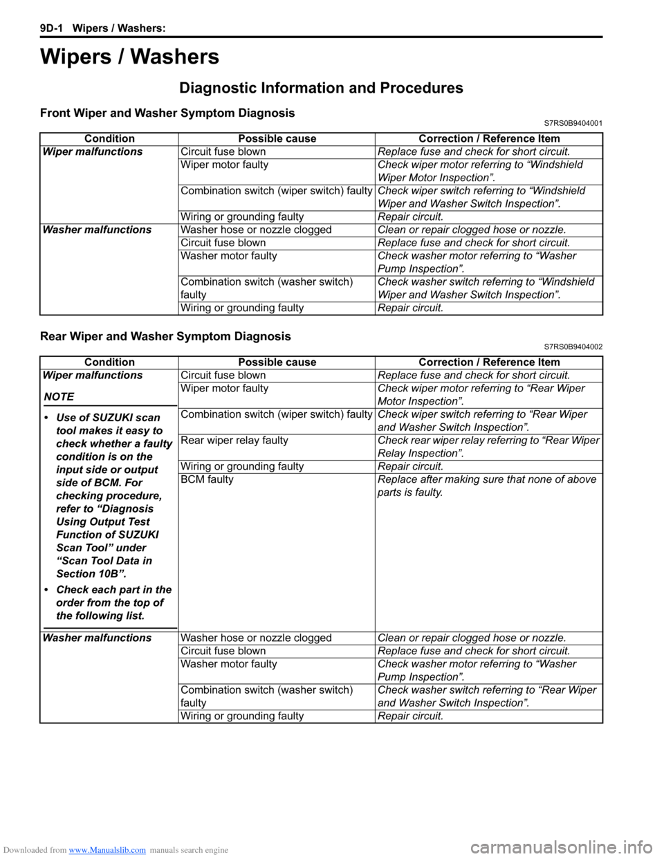
Front Wiper and Washer Symptom DiagnosisS7RS0B9404001
Rear Wiper and Washer Symptom DiagnosisS7RS0B9404002
ConditionPossible cause Correction / Reference Item
Wiper malfunctions Circuit fuse blown Replace fuse and check for short circuit.
Wiper motor faulty Check wiper motor referring to “Windshield
Wiper Motor Inspection”.
Combination switch (wiper switch) faulty Check wiper switch referring to “Windshield
Wiper and Washer Switch Inspection”.
Wiring or grounding faulty Repair circuit.
Washer malfunctions Washer hose or nozzle clogged Clean or repair clogged hose or nozzle.
Circuit fuse blown Replace fuse and check for short circuit.
Washer motor faulty Check washer motor referring to “Washer
Pump Inspection”.
Combination switch (washer switch)
faulty Check washer switch referring to “Windshield
Wiper and Washer Switch Inspection”.
Wiring or grounding faulty Repair circuit.
ConditionPossible cause Correction / Reference Item
Wiper malfunctions
NOTE
• Use of SUZUKI scan tool makes it easy to
check whether a faulty
condition is on the
input side or output
side of BCM. For
checking procedure,
refer to “Diagnosis
Using Output Test
Function of SUZUKI
Scan Tool” under
“Scan Tool Data in
Section 10B”.
• Check each part in the order from the top of
the following list.
Circuit fuse blown Replace fuse and check for short circuit.
Wiper motor faulty Check wiper motor referring to “Rear Wiper
Motor Inspection”.
Combination switch (wiper switch) faulty Check wiper switch referring to “Rear Wiper
and Washer Switch Inspection”.
Rear wiper relay faulty Check rear wiper relay referring to “Rear Wiper
Relay Inspection”.
Wiring or grounding faulty Repair circuit.
BCM faulty Replace after making sure that none of above
parts is faulty.
Washer malfunctions Washer hose or nozzle clogged Clean or repair clogged hose or nozzle.
Circuit fuse blown Replace fuse and check for short circuit.
Washer motor faulty Check washer motor referring to “Washer
Pump Inspection”.
Combination switch (washer switch)
faulty Check washer switch referring to “Rear Wiper
and Washer Switch Inspection”.
Wiring or grounding faulty Repair circuit.
Page 1319 of 1496
Downloaded from www.Manualslib.com manuals search engine Wipers / Washers: 9D-2
Repair Instructions
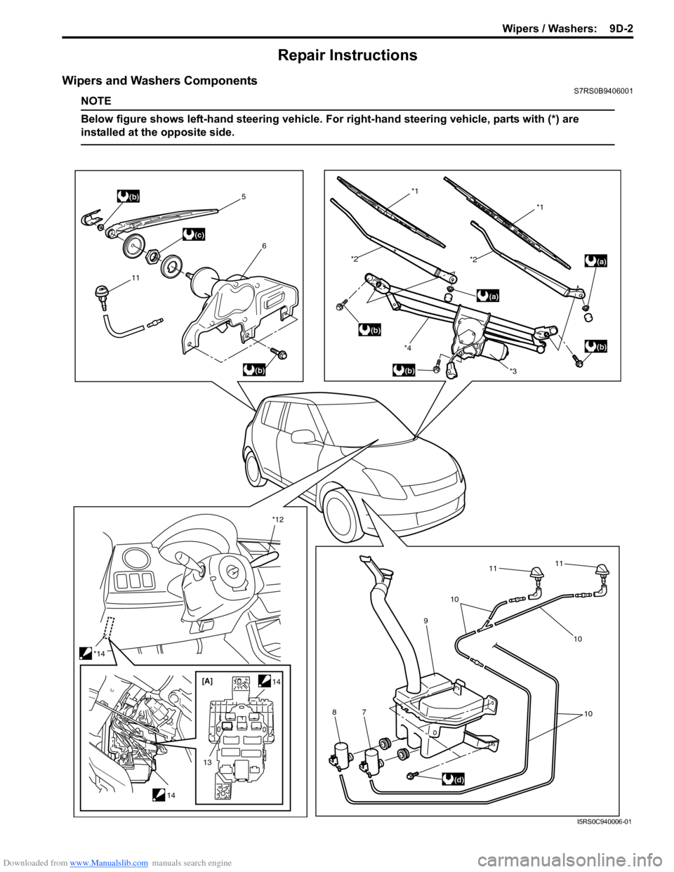
Wipers and Washers ComponentsS7RS0B9406001
NOTE
Below figure shows left-hand steering vehicle. For right-hand steering vehicle, parts with (*) are
installed at the opposite side.
11 5
6
(b)
(b)
(c)
*12
13 14
*14
14[A]
(a)
(a)
(b)
(b)
*3*1
*2
*1
*4
(b)
*2
(d)
7 9
10
10
10
11
118
I5RS0C940006-01
Page 1320 of 1496
Downloaded from www.Manualslib.com manuals search engine 9D-3 Wipers / Washers:
Washer Tank and Washer Pump Removal and
Installation
S7RS0B9406002
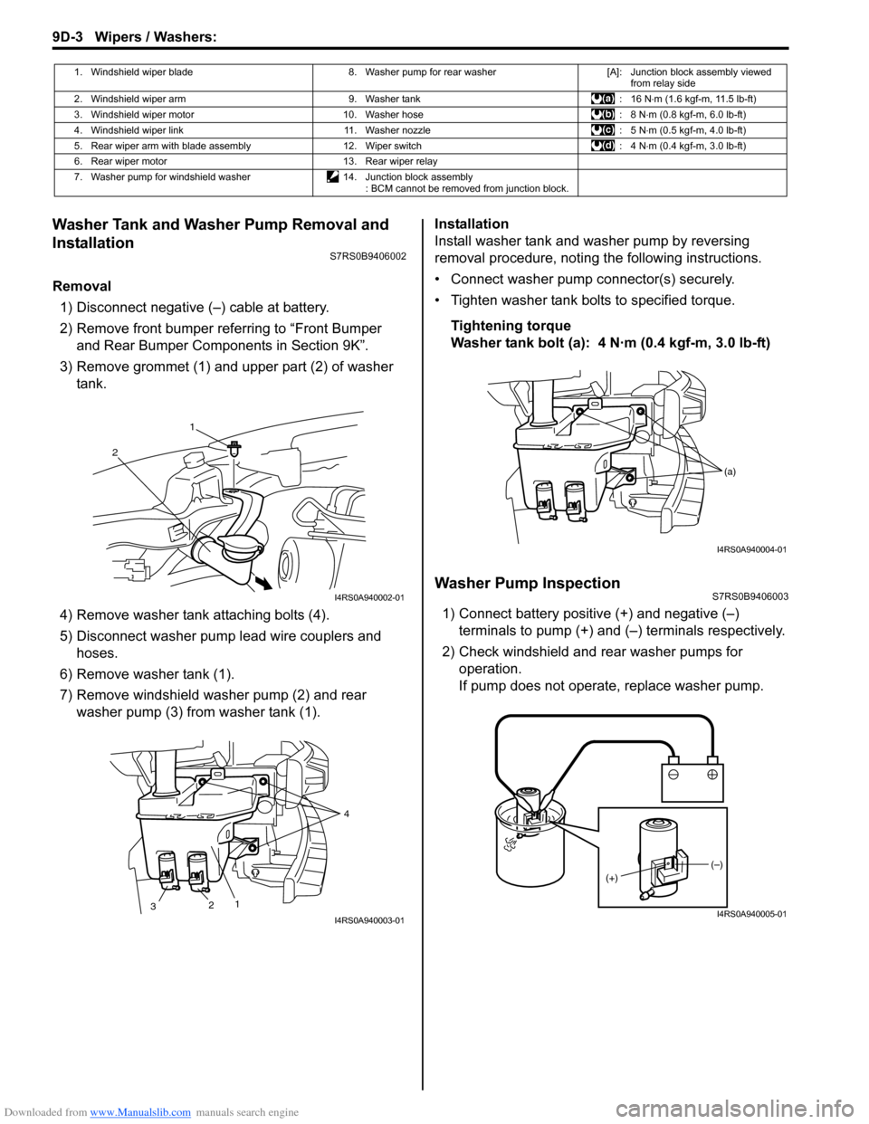
Removal1) Disconnect negative (–) cable at battery.
2) Remove front bumper referring to “Front Bumper and Rear Bumper Components in Section 9K”.
3) Remove grommet (1) and upper part (2) of washer tank.
4) Remove washer tank attaching bolts (4).
5) Disconnect washer pump lead wire couplers and hoses.
6) Remove washer tank (1).
7) Remove windshield washer pump (2) and rear washer pump (3) from washer tank (1). Installation
Install washer tank and washer pump by reversing
removal procedure, noting the following instructions.
• Connect washer pump connector(s) securely.
• Tighten washer tank bolts to specified torque.
Tightening torque
Washer tank bolt (a): 4 N·m (0.4 kgf-m, 3.0 lb-ft)
Washer Pump InspectionS7RS0B9406003
1) Connect battery positive (+) and negative (–) terminals to pump (+) and (–) terminals respectively.
2) Check windshield and rear washer pumps for
operation.
If pump does not operate, replace washer pump.
1. Windshield wiper blade 8. Washer pump for rear washer[A]: Junction block assembly viewed
from relay side
2. Windshield wiper arm 9. Washer tank: 16 N⋅m (1.6 kgf-m, 11.5 lb-ft)
3. Windshield wiper motor 10. Washer hose : 8 N⋅m (0.8 kgf-m, 6.0 lb-ft)
4. Windshield wiper link 11. Washer nozzle : 5 N⋅m (0.5 kgf-m, 4.0 lb-ft)
5. Rear wiper arm with blade assembly 12. Wiper switch : 4 N⋅m (0.4 kgf-m, 3.0 lb-ft)
6. Rear wiper motor 13. Rear wiper relay
7. Washer pump for windshield washer 14. Junction block assembly
: BCM cannot be removed from junction block.
1
2
I4RS0A940002-01
2 1 4
3
I4RS0A940003-01
(a)
I4RS0A940004-01
(–)
(+)
I4RS0A940005-01
Page 1321 of 1496
Downloaded from www.Manualslib.com manuals search engine Wipers / Washers: 9D-4
Windshield Wiper Removal and InstallationS7RS0B9406004
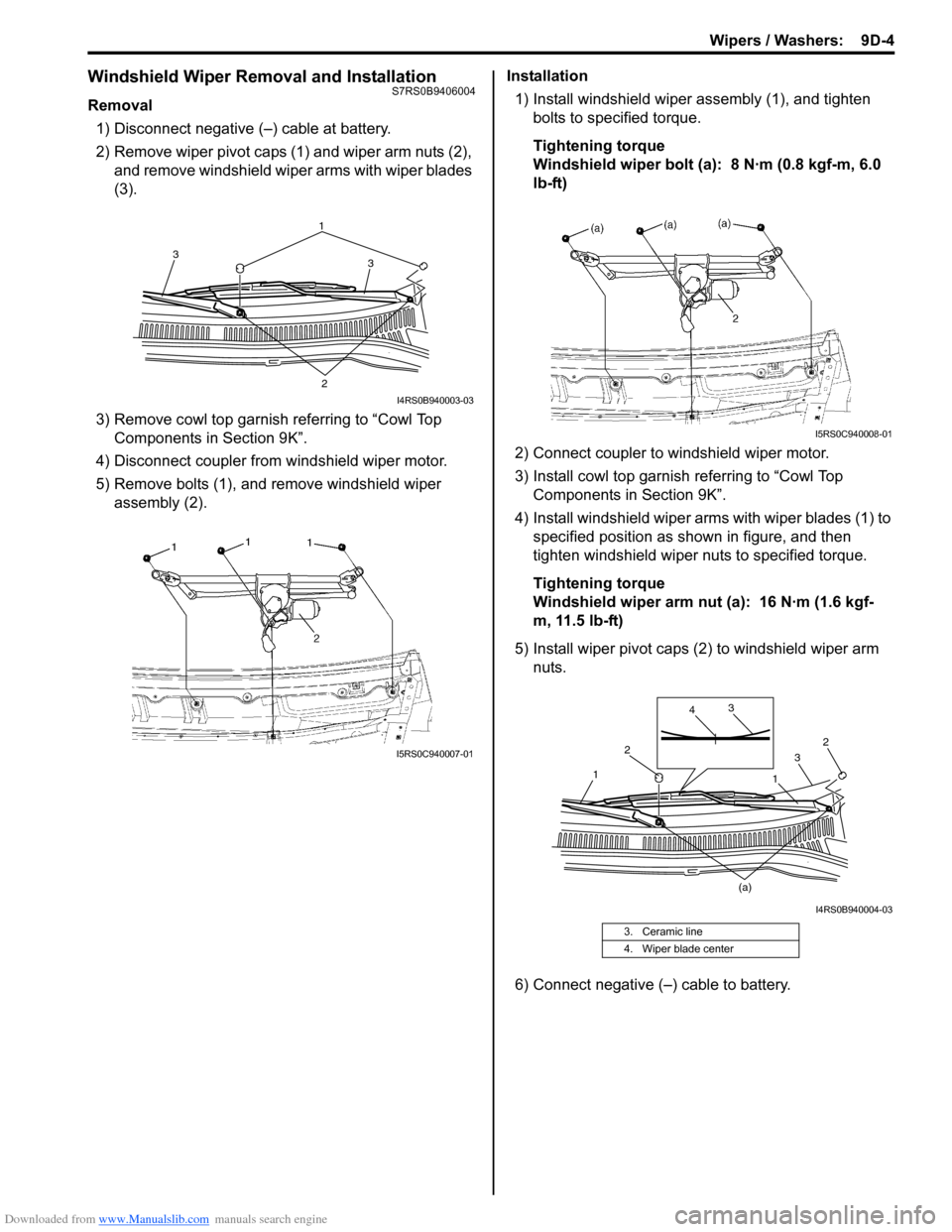
Removal1) Disconnect negative (–) cable at battery.
2) Remove wiper pivot caps (1) and wiper arm nuts (2), and remove windshield wiper arms with wiper blades
(3).
3) Remove cowl top garnish referring to “Cowl Top Components in Section 9K”.
4) Disconnect coupler from windshield wiper motor.
5) Remove bolts (1), and remove windshield wiper assembly (2). Installation
1) Install windshield wiper assembly (1), and tighten bolts to specified torque.
Tightening torque
Windshield wiper bolt (a): 8 N·m (0.8 kgf-m, 6.0
lb-ft)
2) Connect coupler to windshield wiper motor.
3) Install cowl top garnish referring to “Cowl Top
Components in Section 9K”.
4) Install windshield wiper arms with wiper blades (1) to specified position as shown in figure, and then
tighten windshield wiper nuts to specified torque.
Tightening torque
Windshield wiper arm nut (a): 16 N·m (1.6 kgf-
m, 11.5 lb-ft)
5) Install wiper pivot caps (2 ) to windshield wiper arm
nuts.
6) Connect negative (–) cable to battery.
1 3
3
2
I4RS0B940003-03
I5RS0C940007-01
3. Ceramic line
4. Wiper blade center
I5RS0C940008-01
2
2 3
3
4
1
1
(a)
I4RS0B940004-03
Page 1322 of 1496
Downloaded from www.Manualslib.com manuals search engine 9D-5 Wipers / Washers:
Windshield Wiper Motor InspectionS7RS0B9406005
NOTE
Make sure that battery voltage is 12 V or
more.
1) Disconnect negative (–) cable at battery.
2) Remove windshield wiper arms with wiper blades
referring to “Windshield Wiper Removal and
Installation”.
3) Remove cowl top garnish referring to “Cowl Top Components in Section 9K”.
4) Disconnect coupler from windshield wiper motor.
5) Reinstall windshield wiper arms with wiper blade. For
details, refer to Step 4) of “Installation” in “Windshield
Wiper Removal and Installation”.
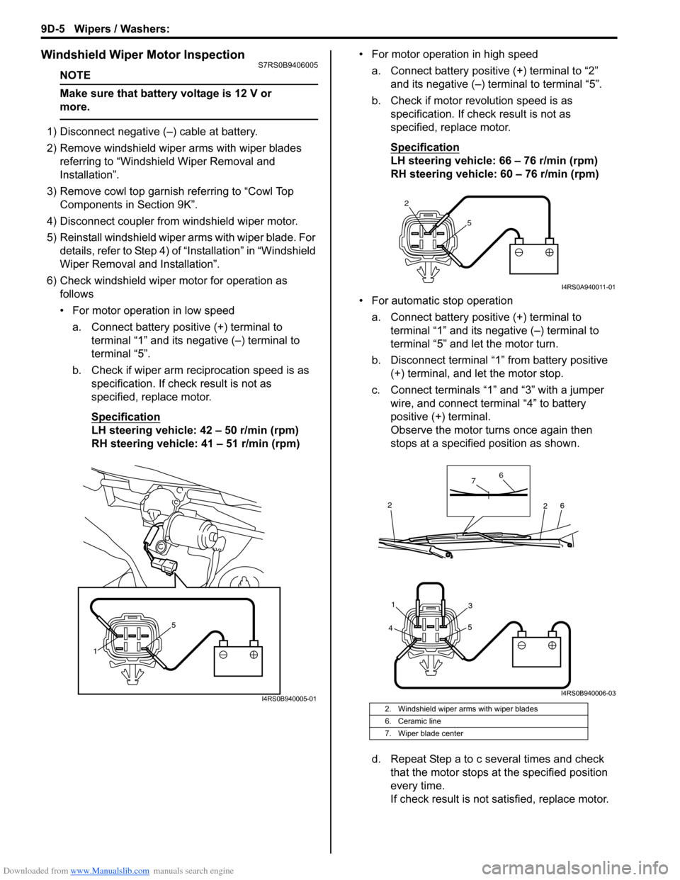
6) Check windshield wiper motor for operation as
follows
• For motor operation in low speed
a. Connect battery positive (+) terminal to terminal “1” and its negative (–) terminal to
terminal “5”.
b. Check if wiper arm reciprocation speed is as specification. If check result is not as
specified, replace motor.
Specification
LH steering vehicle: 42 – 50 r/min (rpm)
RH steering vehicle: 41 – 51 r/min (rpm) • For motor operation in high speed
a. Connect battery positive (+) terminal to “2” and its negative (–) terminal to terminal “5”.
b. Check if motor revolution speed is as specification. If chec k result is not as
specified, replace motor.
Specification
LH steering vehicle: 66 – 76 r/min (rpm)
RH steering vehicle: 60 – 76 r/min (rpm)
• For automatic stop operation a. Connect battery positive (+) terminal to terminal “1” and its negative (–) terminal to
terminal “5” and let the motor turn.
b. Disconnect terminal “1” from battery positive (+) terminal, and let the motor stop.
c. Connect terminals “1” and “3” with a jumper wire, and connect terminal “4” to battery
positive (+) terminal.
Observe the motor turns once again then
stops at a specified position as shown.
d. Repeat Step a to c several times and check that the motor stops at the specified position
every time.
If check result is not satisfied, replace motor.
1 5
I4RS0B940005-012. Windshield wiper arms with wiper blades
6. Ceramic line
7. Wiper blade center
2
5
I4RS0A940011-01
4 5
31
6
6
7
2
2
I4RS0B940006-03