2006 SUZUKI SWIFT warning lights
[x] Cancel search: warning lightsPage 631 of 1496

Downloaded from www.Manualslib.com manuals search engine Electronic Stability Program: 4F-57
3) Remove front brake pipe referring to “Front Brake Hose / Pipe Removal and In stallation in Section 4A”.
4) Remove ESP ® hydraulic unit / control module with
bracket from vehicle by removing bracket bolts.
5) Remove bolt (4) and pull out ESP ® hydraulic unit /
control module assembly (1) from bracket (3) using
flat end rod or the like (2).
Installation 1) Install hydraulic unit / co ntrol module assembly and
by reversing removal procedure.
Tightening torque
Brake pipe flare nut: 16 N·m (1.6 kgf-m, 11.5 lb-
ft)
ESP ® hydraulic unit / control module assembly
bolt: 9 N·m (0.9 kgf-m, 6.5 lb-ft)
ESP ® hydraulic unit / control module assembly
bracket bolt: 25 N·m (2.5 kgf-m, 18.0 lb-ft)
2) Bleed air from brake system referring to “Air Bleeding of Brake System in Section 4A”.
3) Check each installed part for fluid leakage.
4) Connect SUZUKI Scan Tool.
5) Turn ignition switch to ON position. And SLIP indicator lamp flush. (Other than replace with new
one) If other than SLIP indicator lamp light, check
DTC and repair it.
6) Turn ignition switch to ON position. And ESP®
warning lamp, SLIP indicator lamp, ESP ® OFF
lamp, Brake warning lamp lights and ABS warning
lamp flush. (Replace new one)
7) Check DTC.
NOTE
If any DTC(s) other than C1075, C1076 or
C1078 are detected, sensor calibration can
not be completed. Repair the detected it(s)
first.
8) Perform “Sensor Calibration”.
9) Perform “ESP ® Hydraulic Unit Operation Check”.
10) Turn ignition switch to OFF position once and then
ON position. In this state, make sure that indicator
light and warning light turns off.
11) Check DTC(s) are not stored in hydraulic unit / control module.
Front / Rear Wheel Speed Sensor On-Vehicle
Inspection
S7RS0B4606028
CAUTION!
Incorrect voltage and/or wrong connection
cause damage to wheel speed sensor.
Output Voltage Inspection
1) Disconnect negative (–) cable from battery.
2) Hoist vehicle a little.
3) Disconnect wheel speed sensor connector.
4) Disconnect wheel speed grommet from vehicle body.
5) Set up measuring devices as shown in figure, the resistance to 115 Ω and the power supply voltage
to12 V.
4
1
2 3
I6RS0B460030-02
[A]: Front wheel speed sensor 3. “WHT” wire terminal
[B]: Rear wheel speed sensor 4. “BLK” wire terminal
1. Wheel speed sensor connector 5. Power supply (12 V)
2. Resistance (115 Ω)
V
2
5
4 1
3
43
1
[A]
[B]
I6RS0B460031-02
Page 652 of 1496

Downloaded from www.Manualslib.com manuals search engine 5A-8 Automatic Transmission/Transaxle:
Brake Interlock System ConstructionS7RS0B5101004
Shift Lock Solenoid Control
This system consists of shift lock solenoid control
system and interlock cable control system.
The shift lock solenoid cont rol system is so designed
that the select lever can not be shifted from “P” range
position unless ignition switch is turned to “ON” or “ACC”
position and the brake pedal is depressed.
And interlock cable control system is so designed that
select lever cannot be shifted from “P” range position
unless ignition switch is turned to “ACC” or “ON”
position. Also, ignition key cannot be pulled out of key
slot unless select le ver is in “P” range.
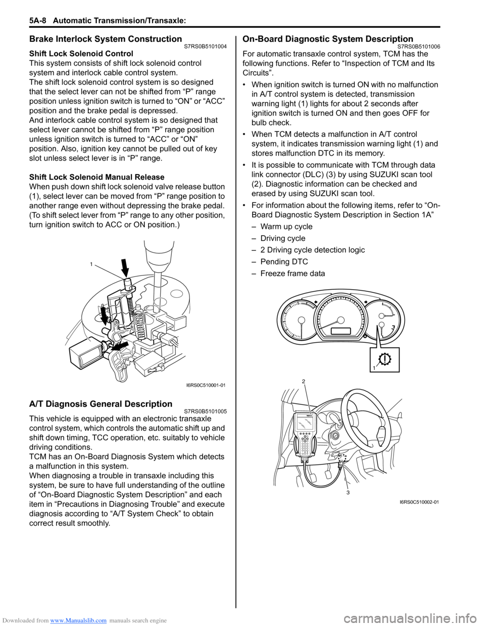
Shift Lock Solenoid Manual Release
When push down shift lock solenoid valve release button
(1), select lever can be moved from “P” range position to
another range even without depressing the brake pedal.
(To shift select lever from “P” range to any other position,
turn ignition switch to ACC or ON position.)
A/T Diagnosis General DescriptionS7RS0B5101005
This vehicle is equipped with an electronic transaxle
control system, which controls the automatic shift up and
shift down timing, TCC operation, etc. suitably to vehicle
driving conditions.
TCM has an On-Board Diagnosis System which detects
a malfunction in this system.
When diagnosing a trouble in transaxle including this
system, be sure to have full understanding of the outline
of “On-Board Diagnostic System Description” and each
item in “Precautions in Diagnosing Trouble” and execute
diagnosis according to “A/T System Check” to obtain
correct result smoothly.
On-Board Diagnostic System DescriptionS7RS0B5101006
For automatic transaxle co ntrol system, TCM has the
following functions. Refer to “Inspection of TCM and Its
Circuits”.
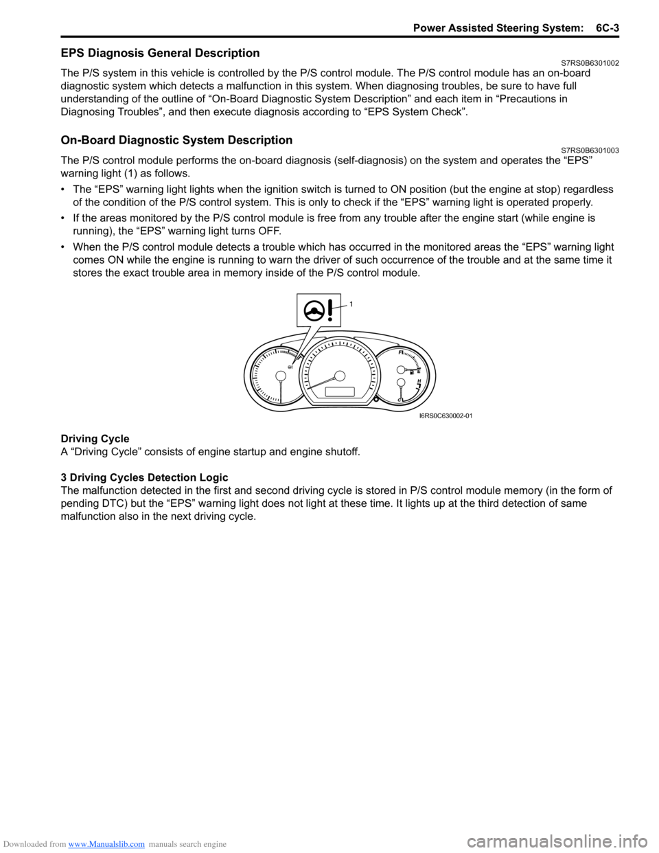
• When ignition switch is turned ON with no malfunction in A/T control system is detected, transmission
warning light (1) lights for about 2 seconds after
ignition switch is turned ON and then goes OFF for
bulb check.
• When TCM detects a malfunction in A/T control system, it indicates transmission warning light (1) and
stores malfunction DTC in its memory.
• It is possible to communicate with TCM through data link connector (DLC) (3) by using SUZUKI scan tool
(2). Diagnostic information can be checked and
erased by using SUZUKI scan tool.
• For information about the following items, refer to “On- Board Diagnostic System De scription in Section 1A”
– Warm up cycle
– Driving cycle
– 2 Driving cycle detection logic
– Pending DTC
– Freeze frame data
1
I6RS0C510001-01
3
2
1
I6RS0C510002-01
Page 662 of 1496

Downloaded from www.Manualslib.com manuals search engine 5A-18 Automatic Transmission/Transaxle:
Visual InspectionS7RS0B5104002
Visually check the following parts and systems.
Malfunction Indicator Lamp (MIL) CheckS7RS0B5104003
Refer to the same item in “Malfunction Indicator Lam p (MIL) Check in Section 1A” for checking procedure.
Transmission Warning Light CheckS7RS0B5104004
1) Turn ignition switch ON.
2) Check that transmission warning light lights for about 2 – 4 sec. and then goes OFF.
If anything faulty is found, advance “Transmission Warn ing Light Circuit Check – Light Does Not Come “ON” at
Ignition Switch ON” or “Transmission Warning Light Circu it Check – Light Remains “ON” at Ignition Switch ON”.
Inspection item Referring
• A/T fluid ----- level, leakage, color “Automatic Transaxle Fluid Level Inspection in Section 0B”
• A/T fluid hoses ----- disconnection, looseness, deterioration “A/T Fluid Cooler Hoses Replacement”
• A/T select cable ----- installation “S elect Cable Removal and Installation”
• Engine oil ----- level, leakage “Engine Oil and Filter Change in Section 0B”
• Engine coolant ----- level, leakage “Engine Coolant Change in Section 0B”
• Engine mountings ----- play, looseness, damage “Engine Assembly Removal and Installation in Section 1D”
• Suspension ----- play, looseness “Suspension, Wheels and Tires Symptom Diagnosis in Section 2A”
• Drive shafts ----- damage “Front Drive Shaft Assembly On-Vehicle Inspection in Section 3A”
• Battery ----- indicator condition, corrosion of terminal “Battery Inspection in Section 1J”
• Connectors of electric wire harness ----- disconnection, friction “Electronic Shift Control System Components
Location”
• Fuses ----- burning
• Parts ----- installation, damage
• Bolts ----- looseness
• Other parts that can be checked visually
Also check the following items at engine start, if possible.
• Transmission warning light (if equipped) ----- Operation “Transmission Warning Light Check”
• Malfunction indicator lamp ----- Operation “Malfunction Indicator Lamp (MIL) Check”
• Charge warning lamp ----- Operation “Generator Symptom Diagnosis in Section 1J”
• Engine oil pressure warning lamp ----- Operation “Oil Pressure Warning Ligh t Symptom Diagnosis in
Section 9C”
• Engine coolant temp. meter ----- Operation “Engine Coolant Temperature (ECT) Meter
Symptom Diagnosis in Section 9C”
• Other parts that can be checked visually
I4RS0A510008-01
Page 687 of 1496

Downloaded from www.Manualslib.com manuals search engine Automatic Transmission/Transaxle: 5A-43
Transmission Warning Light Circuit Check – Light Does Not Come “ON” at Ignition Switch ONS7RS0B5104021
Troubleshooting
Transmission Warning Light Circuit Check – Light Remains “ON” at Ignition Switch ONS7RS0B5104022
TroubleshootingStep Action Yes No
1 Was “A/T System Check” performed? Go to Step 2. Go to “A/T System
Check”.
2 Check DTC
Is DTC P0705, P0707, P0712, P0713, P0717, P0722,
P0787, P0788, P0961, P0962, P0963, P0973, P0974,
P0976, P0977, P1702, P1703, P1774, P1777, P2762,
P2763 and/or P2764 detected? Go to applicable DTC
diag. flow.
Go to Step 3.
3 Brake light switch signal inspection
1) With ignition switch turned ON, check voltage between
terminal “C35-20” of ECM connector and ground.
Brake light switch signal specification
Brake pedal is released: 0 – 1 V
Brake pedal is depressed: 8 – 14 V
Is result as specified? Substitute a known-
good TCM and recheck.
Mis-adjusted brake light
switch or faulty brake
light switch.
Step
Action YesNo
1 Combination meter power supply check
1) Turn ignition switch ON.
Does other indicator / warnin g lights in combination meter
comes ON? Go to Step 2.
Repair combination
meter power supply
circuit referring to “C-1
Combination Meter
Circuit Diagram (Meter)
in Section 9A”.
2 TCM power and ground circuit check
1) Check referring to “TCM Power and Ground Circuit
Check”.
Is it in good condition? Go to Step 3.
Repair or replace.
3 DTC check
1) Check DTC referring to “DTC Check”.
Is there DTC P1774? Go to applicable DTC
diag. flow.
Go to Step 4.
4 Combination meter function check
1) Turn ignition switch ON.
Does A/T selector position in dicator show correct select
lever position? Replace combination
meter.
Substitute a known-
good TCM and recheck.
Step
Action YesNo
1 Diagnostic Trouble Code (DTC) Check
1) Check DTC referring to “DTC Check”.
Is there any DTC(s)? Perform DTC Flow to
repair and retry.
Substitute a known-
good TCM and recheck.
If OK, substitute a
known-good
combination meter and
recheck.
Page 885 of 1496

Downloaded from www.Manualslib.com manuals search engine Power Assisted Steering System: 6C-3
EPS Diagnosis General DescriptionS7RS0B6301002
The P/S system in this vehicle is controlled by the P/S control module. T he P/S control module has an on-board
diagnostic system which detects a malfunction in this system. When diagnosing troubles, be sure to have full
understanding of the outline of “On-Board Diagnostic Sy stem Description” and each item in “Precautions in
Diagnosing Troubles”, and then execute diagnosis according to “EPS System Check”.
On-Board Diagnostic System DescriptionS7RS0B6301003
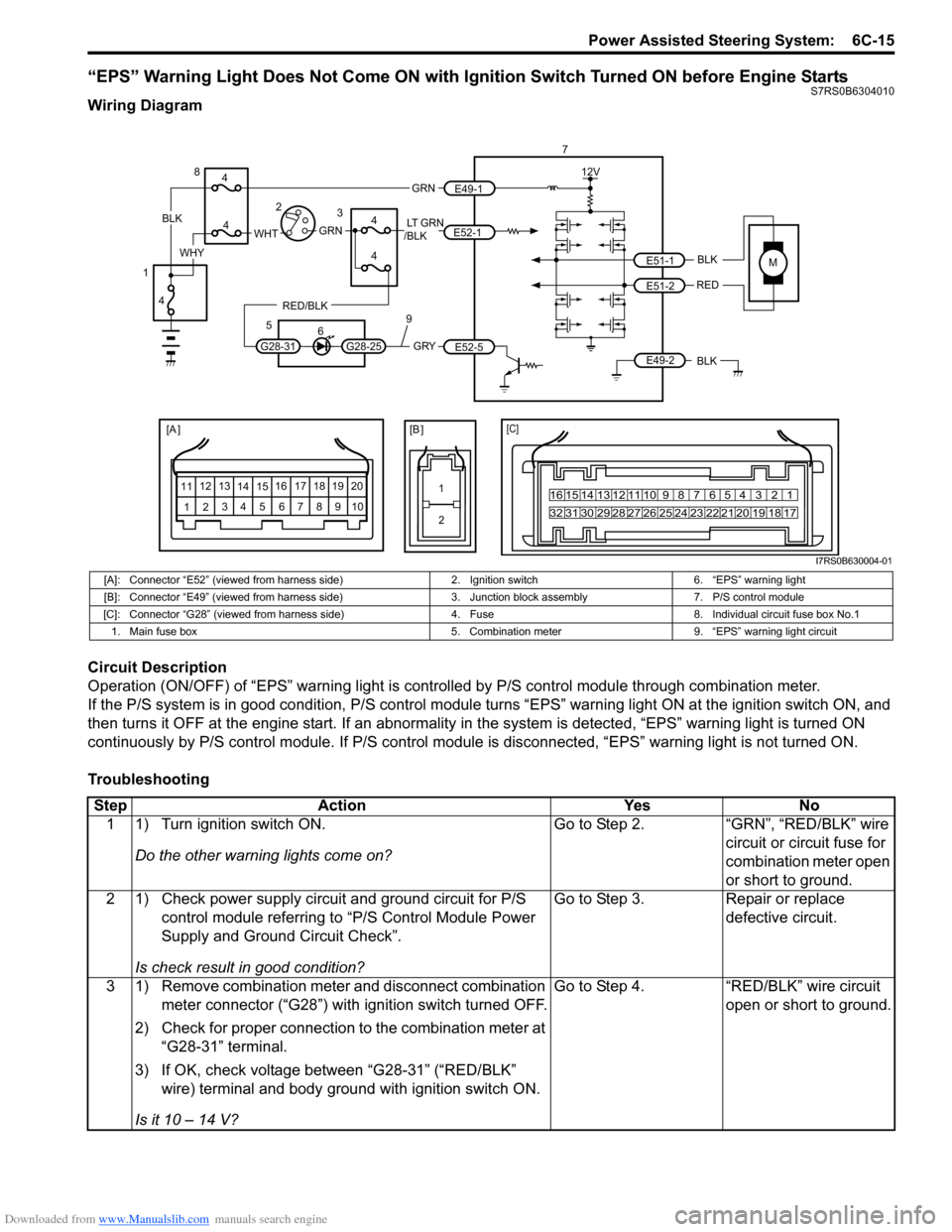
The P/S control module performs the on -board diagnosis (self-diagnosis) on the system and operates the “EPS”
warning light (1) as follows.
• The “EPS” warning light lights when the ignition switch is turned to ON position (but the engine at stop) regardless
of the condition of the P/S co ntrol system. This is only to check if the “EPS” warning light is operated properly.
• If the areas monitored by the P/S control module is free from any trouble after the engine start (while engine is
running), the “EPS” warning light turns OFF.
• When the P/S control module detects a trouble which has occurred in th e monitored areas the “EPS” warning light
comes ON while the engine is running to warn the driver of such occurrence of the trouble and at the same time it
stores the exact trouble area in memory inside of the P/S control module.
Driving Cycle
A “Driving Cycle” consists of en gine startup and engine shutoff.
3 Driving Cycles Detection Logic
The malfunction detected in the first and second driving cycl e is stored in P/S control module memory (in the form of
pending DTC) but the “EPS” wa rning light does not light at these time. It lights up at t he third detection of same
malfunction also in the next driving cycle.
1
I6RS0C630002-01
Page 890 of 1496

Downloaded from www.Manualslib.com manuals search engine 6C-8 Power Assisted Steering System:
Step 2: DTC Check, Record and Clearance
First, check DTC, referring to “DTC Check”. If DTC is
indicated, print it or write them down and then clear them
by referring to “DTC Clearance”. DTC indicates
malfunction that occurred in the system but does not
indicate whether it exists now or it occurred in the past
and the normal condition has been restored now. To
check which case applies, check the symptom in
question according to Step 5 and recheck DTC
according to Step 6 and 7.
Attempt to diagnose a trouble based on DTC in this step
only or failure to clear the DTC in this step will lead to
incorrect diagnosis, trouble diagnosis of a normal circuit
or difficulty in troubleshooting.
Step 3 and 4: Visual Inspection
As a preliminary step, be sure to perform visual check of
the items that support proper function of the P/S system
referring to “Visual Inspection”.
Step 5: Trouble Symptom Confirmation
Based on information obtained in “Step 1: Customer
Complaint Analysis: ” and “S tep 2: DTC Check, Record
and Clearance: ”, confirm trouble symptoms. Also,
reconfirm trouble symptom by performing test drive and
turning steering wheel fully to right and left at stopped
vehicle.
Step 6 and 7: Rechecking and Record of DTC
Refer to “DTC Check” for checking procedure.
Step 8: Steering Symptom Diagnosis and P/S
System Symptom Diagnosis
Perform basic steering system check according to
“Steering Symptom Diagnosis in Section 6A” first. When
the end of the flow has been reached, check the parts of
the system suspected as a possible cause referring to
“P/S System Symptom Diagnosis” and based on
symptoms appearing on the vehicle (symptoms obtained
through steps of customer complaint analysis, trouble
symptom confirmation and/or basic P/S system check)
and repair or replace faulty parts, if any.
Step 9: Troubleshooting for DTC (See each DTC
Diag. Flow)
Based on the DTC indicated in Step 6 or 7 and referring
to the applicable DTC diag. flow, locate the cause of the
trouble, namely in a sensor, switch, wire harness,
connector, actuator, P/S control module or other part and
repair or replace faulty parts.
Step 10: Intermittent Problems Check
Check parts where an intermittent trouble is easy to
occur (e.g., wire harness, connector, etc.), referring to
“Intermittent and Poor Connection Inspection in Section
00” and related circuit of DTC recorded in Step 2. Step 11: Final Confirmation Test
Confirm that the problem symptom has gone and the P/
S system is free from any abnormal conditions. If what
has been repaired is related to the DTC, clear the DTC
once, perform DTC confirmation procedure and confirm
that no DTC is indicated.
“EPS” Warning Light CheckS7RS0B6304002
1) Turn ignition switch to ON position (without engine
running) and chec k if the “EPS” warning light (1)
lights up. If the light dose not light up, go to ““EPS”
Warning Light Does Not Come ON with Ignition
Switch Turned ON before Engine Starts” of the
diagnostic flows.
2) Start engine and check if the “EPS” warning light turns OFF. If light remains ON and no DTC is stored
in P/S control module, go to ““EPS” Warning Light
Remains ON Steady after Engine Starts” for
troubleshooting.
DTC CheckS7RS0B6304003
1) Turn ignition switch to OFF position.
2) Connect SUZUKI scan tool to data link connector (DLC) (1) located on underside of instrument panel
at driver’s seat side.
Special tool
(A): SUZUKI scan tool
1
I6RS0C630002-01
(A)
1
I4RS0B450003-01
Page 897 of 1496

Downloaded from www.Manualslib.com manuals search engine Power Assisted Steering System: 6C-15
“EPS” Warning Light Does Not Come ON with Ignition Switch Turned ON before Engine StartsS7RS0B6304010
Wiring Diagram
Circuit Description
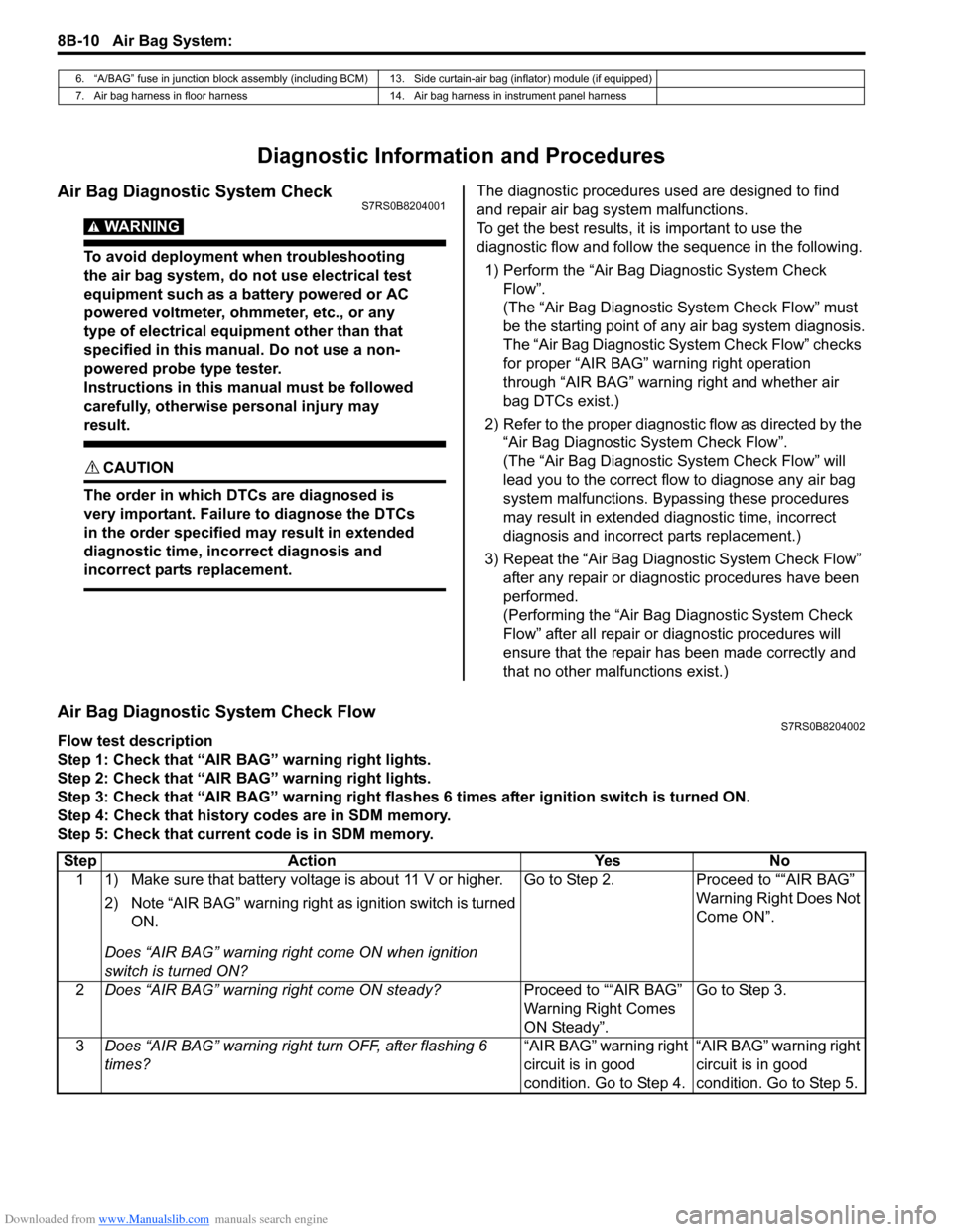
Operation (ON/OFF) of “EPS” warning light is controlled by P/S control module through combination meter.
If the P/S system is in good condition, P/S control module turns “ EPS” warning light ON at the ignition switch ON, and
then turns it OFF at the engine start. If an abnormality in the system is detected, “EPS” warning light is turned ON
continuously by P/S control module. If P/S control module is disconnected, “EPS” warning light is not turned ON.
Troubleshooting
MBLK
REDE51-1
E51-2
[A ]
12 3
4 5 67
89
11
10
12 13
141516
17 18 19 2010 9 8 7654 3 21
16 15 14 13 12 11
26 25 24 2322 21 20 19 18 17
32 31 30 29 28 27
[C]
7
12V
E49-2BLK
[B ]
1 2
GRY
LT GRN
/BLK
E52-1
E52-5
E49-1
GRNGRNWHTBLK
WHY
G28-25G28-31
RED/BLK
8
3
4
4
5 6
4
4
1 2
4
9
I7RS0B630004-01
[A]: Connector “E52” (viewed from harness side) 2. Ignition switch6. “EPS” warning light
[B]: Connector “E49” (viewed from harness side) 3. Junction block assembly7. P/S control module
[C]: Connector “G28” (viewed from harness si de)4. Fuse 8. Individual circuit fuse box No.1
1. Main fuse box 5. Combination meter9. “EPS” warning light circuit
StepAction YesNo
1 1) Turn ignition switch ON.
Do the other warning lights come on? Go to Step 2.
“GRN”, “RED/BLK” wire
circuit or circuit fuse for
combination meter open
or short to ground.
2 1) Check power supply circuit and ground circuit for P/S control module referring to “P/S Control Module Power
Supply and Ground Circuit Check”.
Is check result in good condition? Go to Step 3.
Repair or replace
defective circuit.
3 1) Remove combination meter and disconnect combination meter connector (“G28”) with ignition switch turned OFF.
2) Check for proper connection to the combination meter at “G28-31” terminal.
3) If OK, check voltage between “G28-31” (“RED/BLK” wire) terminal and body ground with ignition switch ON.
Is it 10 – 14 V? Go to Step 4.
“RED/BLK” wire circuit
open or short to ground.
Page 1048 of 1496

Downloaded from www.Manualslib.com manuals search engine 8B-10 Air Bag System:
Diagnostic Information and Procedures
Air Bag Diagnostic System CheckS7RS0B8204001
WARNING!
To avoid deployment when troubleshooting
the air bag system, do not use electrical test
equipment such as a battery powered or AC
powered voltmeter, ohmmeter, etc., or any
type of electrical equipment other than that
specified in this manual. Do not use a non-
powered probe type tester.
Instructions in this manual must be followed
carefully, otherwise personal injury may
result.
CAUTION!
The order in which DTCs are diagnosed is
very important. Failure to diagnose the DTCs
in the order specified may result in extended
diagnostic time, incorrect diagnosis and
incorrect parts replacement.
The diagnostic procedures used are designed to find
and repair air bag system malfunctions.
To get the best results, it is important to use the
diagnostic flow and follow the sequence in the following.1) Perform the “Air Bag Diagnostic System Check Flow”.
(The “Air Bag Diagnostic System Check Flow” must
be the starting point of any air bag system diagnosis.
The “Air Bag Diagnostic System Check Flow” checks
for proper “AIR BAG” warning right operation
through “AIR BAG” warning right and whether air
bag DTCs exist.)
2) Refer to the proper diagnost ic flow as directed by the
“Air Bag Diagnostic System Check Flow”.
(The “Air Bag Diagnostic System Check Flow” will
lead you to the correct flow to diagnose any air bag
system malfunctions. Bypassing these procedures
may result in extended diagnostic time, incorrect
diagnosis and incorrect parts replacement.)
3) Repeat the “Air Bag Diagnostic System Check Flow” after any repair or diagnostic procedures have been
performed.
(Performing the “Air Bag Diagnostic System Check
Flow” after all repair or diagnostic procedures will
ensure that the repair has been made correctly and
that no other malfunctions exist.)
Air Bag Diagnostic System Check FlowS7RS0B8204002
Flow test description
Step 1: Check that “AIR BAG” warning right lights.
Step 2: Check that “AIR BAG” warning right lights.
Step 3: Check that “AIR BAG” warning right flas hes 6 times after ignition switch is turned ON.
Step 4: Check that history codes are in SDM memory.
Step 5: Check that current code is in SDM memory.
6. “A/BAG” fuse in junction block assembly (including BCM) 13. Side curtain-air bag (inflator) module (if equipped)
7. Air bag harness in floor harness 14. Air bag harness in instrument panel harness
Step Action YesNo
1 1) Make sure that battery voltage is about 11 V or higher.
2) Note “AIR BAG” warning right as ignition switch is turned
ON.
Does “AIR BAG” warning ri ght come ON when ignition
switch is turned ON? Go to Step 2.
Proceed to ““AIR BAG”
Warning Right Does Not
Come ON”.
2 Does “AIR BAG” warning right come ON steady? Proceed to ““AIR BAG”
Warning Right Comes
ON Steady”.Go to Step 3.
3 Does “AIR BAG” warning right turn OFF, after flashing 6
times? “AIR BAG” warning right
circuit is in good
condition. Go to Step 4.“AIR BAG” warning right
circuit is in good
condition. Go to Step 5.