2006 SUZUKI SWIFT spark plug inspection
[x] Cancel search: spark plug inspectionPage 96 of 1496
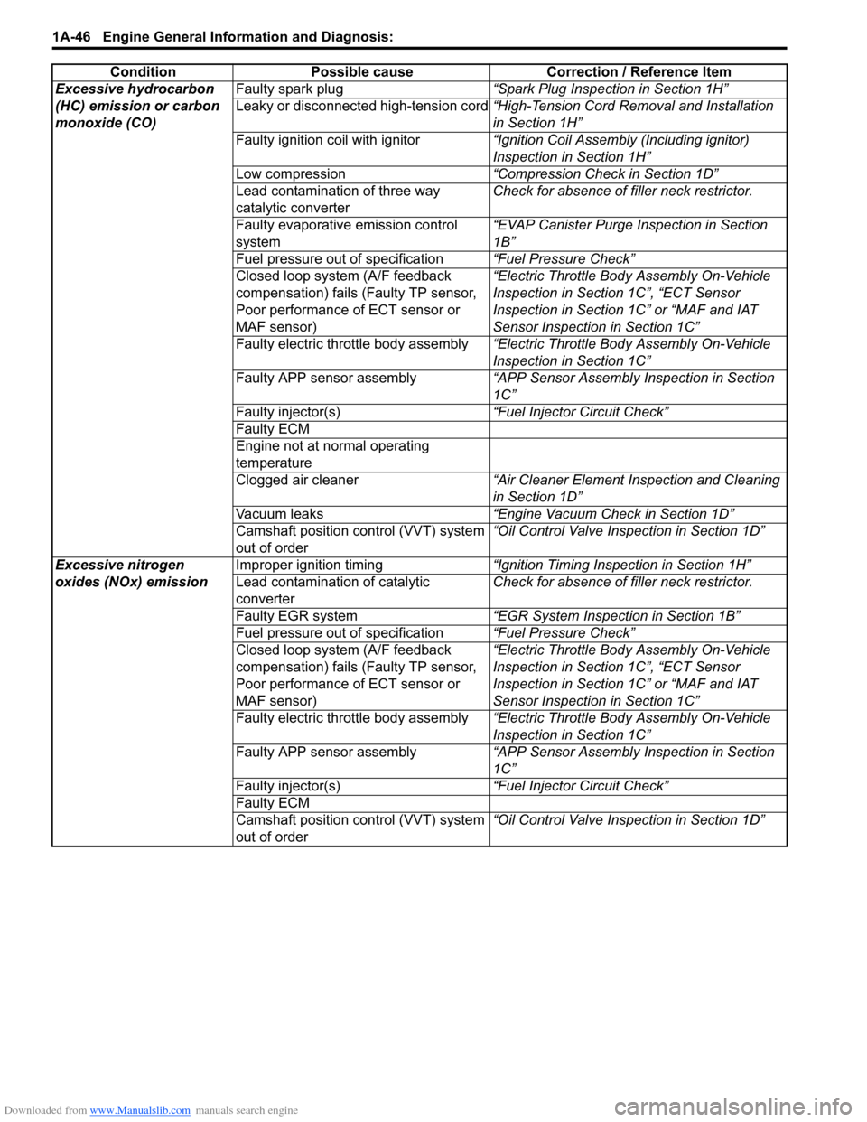
Downloaded from www.Manualslib.com manuals search engine 1A-46 Engine General Information and Diagnosis:
Excessive hydrocarbon
(HC) emission or carbon
monoxide (CO)Faulty spark plug
“Spark Plug Inspection in Section 1H”
Leaky or disconnected high-tension cord “High-Tension Cord Removal and Installation
in Section 1H”
Faulty ignition coil with ignitor “Ignition Coil Assembly (Including ignitor)
Inspection in Section 1H”
Low compression “Compression Check in Section 1D”
Lead contamination of three way
catalytic converter Check for absence of f
iller neck restrictor.
Faulty evaporative emission control
system “EVAP Canister Purge Inspection in Section
1B”
Fuel pressure out of specification “Fuel Pressure Check”
Closed loop system (A/F feedback
compensation) fails (Faulty TP sensor,
Poor performance of ECT sensor or
MAF sensor) “Electric Throttle Body Assembly On-Vehicle
Inspection in Section 1C”, “ECT Sensor
Inspection in Section 1C” or “MAF and IAT
Sensor Inspection in Section 1C”
Faulty electric throttle body assembly “Electric Throttle Body Assembly On-Vehicle
Inspection in Section 1C”
Faulty APP sensor assembly “APP Sensor Assembly Inspection in Section
1C”
Faulty injector(s) “Fuel Injector Circuit Check”
Faulty ECM
Engine not at normal operating
temperature
Clogged air cleaner “Air Cleaner Element Inspection and Cleaning
in Section 1D”
Vacuum leaks “Engine Vacuum Check in Section 1D”
Camshaft position control (VVT) system
out of order “Oil Control Valve Inspection in Section 1D”
Excessive nitrogen
oxides (NOx) emission Improper ignition timing
“Ignition Timing Inspection in Section 1H”
Lead contamination of catalytic
converter Check for absence of f
iller neck restrictor.
Faulty EGR system “EGR System Inspection in Section 1B”
Fuel pressure out of specification “Fuel Pressure Check”
Closed loop system (A/F feedback
compensation) fails (Faulty TP sensor,
Poor performance of ECT sensor or
MAF sensor) “Electric Throttle Body Assembly On-Vehicle
Inspection in Section 1C”, “ECT Sensor
Inspection in Section 1C” or “MAF and IAT
Sensor Inspection in Section 1C”
Faulty electric throttle body assembly “Electric Throttle Body Assembly On-Vehicle
Inspection in Section 1C”
Faulty APP sensor assembly “APP Sensor Assembly Inspection in Section
1C”
Faulty injector(s) “Fuel Injector Circuit Check”
Faulty ECM
Camshaft position control (VVT) system
out of order “Oil Control Valve Inspection in Section 1D”
Condition Possible cause Correction / Reference Item
Page 156 of 1496
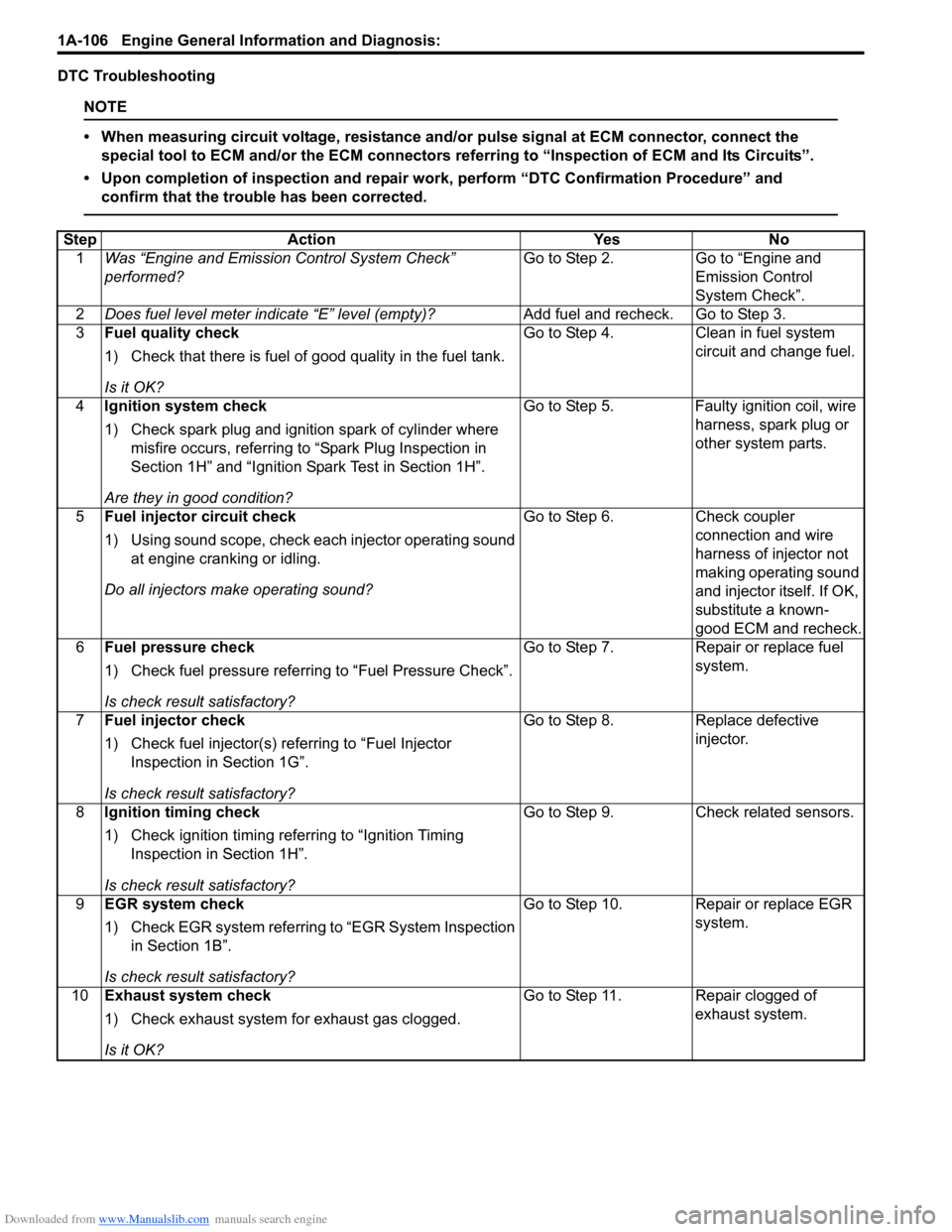
Downloaded from www.Manualslib.com manuals search engine 1A-106 Engine General Information and Diagnosis:
DTC Troubleshooting
NOTE
• When measuring circuit voltage, resistance and/or pulse signal at ECM connector, connect the
special tool to ECM and/or the ECM connectors re ferring to “Inspection of ECM and Its Circuits”.
• Upon completion of inspection and repair work, perform “DTC Confirmation Procedure” and confirm that the trouble has been corrected.
Step Action YesNo
1 Was “Engine and Emission Control System Check”
performed? Go to Step 2.
Go to “Engine and
Emission Control
System Check”.
2 Does fuel level meter in dicate “E” level (empty)? Add fuel and recheck. Go to Step 3.
3 Fuel quality check
1) Check that there is fuel of good quality in the fuel tank.
Is it OK? Go to Step 4.
Clean in fuel system
circuit and change fuel.
4 Ignition system check
1) Check spark plug and ignition spark of cylinder where
misfire occurs, referring to “Spark Plug Inspection in
Section 1H” and “Ignition Spark Test in Section 1H”.
Are they in good condition? Go to Step 5.
Faulty ignition coil, wire
harness, spark plug or
other system parts.
5 Fuel injector circuit check
1) Using sound scope, check each injector operating sound
at engine cranking or idling.
Do all injectors ma ke operating sound? Go to Step 6.
Check coupler
connection and wire
harness of injector not
making operating sound
and injector itself. If OK,
substitute a known-
good ECM and recheck.
6 Fuel pressure check
1) Check fuel pressure referring to “Fuel Pressure Check”.
Is check result satisfactory? Go to Step 7.
Repair or replace fuel
system.
7 Fuel injector check
1) Check fuel injector(s) re ferring to “Fuel Injector
Inspection in Section 1G”.
Is check result satisfactory? Go to Step 8.
Replace defective
injector.
8 Ignition timing check
1) Check ignition timing referring to “Ignition Timing
Inspection in Section 1H”.
Is check result satisfactory? Go to Step 9.
Check related sensors.
9 EGR system check
1) Check EGR system referring to “EGR System Inspection
in Section 1B”.
Is check result satisfactory? Go to Step 10. Repair or replace EGR
system.
10 Exhaust system check
1) Check exhaust system for exhaust gas clogged.
Is it OK? Go to Step 11. Repair clogged of
exhaust system.
Page 165 of 1496
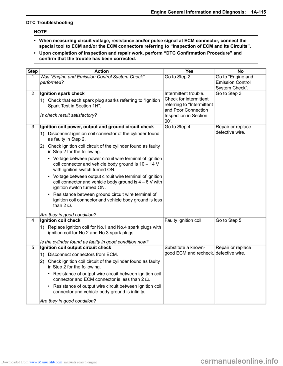
Downloaded from www.Manualslib.com manuals search engine Engine General Information and Diagnosis: 1A-115
DTC Troubleshooting
NOTE
• When measuring circuit voltage, resistance and/or pulse signal at ECM connector, connect the
special tool to ECM and/or the ECM connectors re ferring to “Inspection of ECM and Its Circuits”.
• Upon completion of inspection and repair work, perform “DTC Confirmation Procedure” and confirm that the trouble has been corrected.
Step Action YesNo
1 Was “Engine and Emission Control System Check”
performed? Go to Step 2.
Go to “Engine and
Emission Control
System Check”.
2 Ignition spark check
1) Check that each spark plug sparks referring to “Ignition
Spark Test in Section 1H”.
Is check result satisfactory? Intermittent trouble.
Check for intermittent
referring to “Intermittent
and Poor Connection
Inspection in Section
00”.Go to Step 3.
3 Ignition coil power, output and ground circuit check
1) Disconnect ignition coil connector of the cylinder found
as faulty in Step 2.
2) Check ignition coil circuit of the cylinder found as faulty in Step 2 for the following.
• Voltage between power circuit wire terminal of ignition coil connector and vehicle body ground is 10 – 14 V
with ignition switch turned ON.
• Voltage between output circuit wire terminal of ignition coil connector and vehicle body ground is 4 – 6 V with
ignition switch turned ON.
• Resistance between ground circuit wire terminal of ignition coil connector and vehicle body ground is less
than 2 Ω.
Are they in good condition? Go to Step 4.
Repair or replace
defective wire.
4 Ignition coil check
1) Replace ignition coil for No.1 and No.4 spark plugs with
ignition coil for No.2 and No.3 spark plugs.
Is the cylinder found as faulty in good condition now? Faulty ignition coil. Go to Step 5.
5 Ignition coil output circuit check
1) Disconnect connectors from ECM.
2) Check ignition coil circuit of the cylinder found as faulty
in Step 2 for the following.
• Resistance of output wire circuit between ignition coil
connector and ECM connector is less than 2 Ω.
• Resistance of output wire circuit between ignition coil connector and vehicle b ody ground is infinity.
Are they in good condition? Substitute a known-
good ECM and recheck.
Repair or replace
defective wire.
Page 396 of 1496
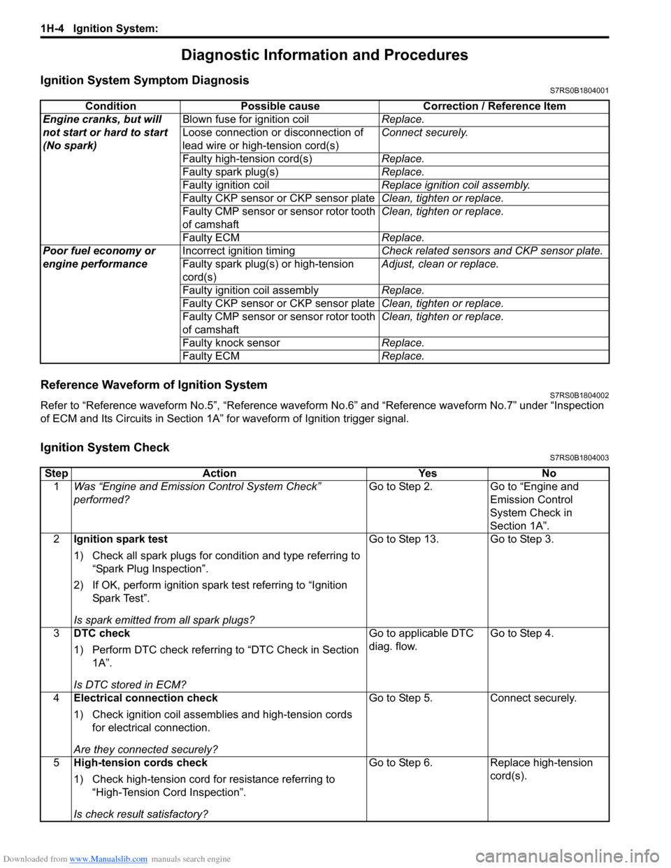
Downloaded from www.Manualslib.com manuals search engine 1H-4 Ignition System:
Diagnostic Information and Procedures
Ignition System Symptom DiagnosisS7RS0B1804001
Reference Waveform of Ignition SystemS7RS0B1804002
Refer to “Reference waveform No.5”, “Reference waveform No.6” and “Reference waveform No.7” under “Inspection
of ECM and Its Circuits in Section 1A” for waveform of Ignition trigger signal.
Ignition System CheckS7RS0B1804003
Condition Possible cause Correction / Reference Item
Engine cranks, but will
not start or hard to start
(No spark) Blown fuse for ignition coil
Replace.
Loose connection or disconnection of
lead wire or high-tension cord(s) Connect securely.
Faulty high-tension cord(s) Replace.
Faulty spark plug(s) Replace.
Faulty ignition coil Replace ignition coil assembly.
Faulty CKP sensor or CKP sensor plate Clean, tighten or replace.
Faulty CMP sensor or sensor rotor tooth
of camshaft Clean, tighten or replace.
Faulty ECM Replace.
Poor fuel economy or
engine performance Incorrect ignition timing
Check related sensors and CKP sensor plate.
Faulty spark plug(s) or high-tension
cord(s) Adjust, clean or replace.
Faulty ignition coil assembly Replace.
Faulty CKP sensor or CKP sensor plate Clean, tighten or replace.
Faulty CMP sensor or sensor rotor tooth
of camshaft Clean, tighten or replace.
Faulty knock sensor Replace.
Faulty ECM Replace.
StepAction YesNo
1 Was “Engine and Emission Control System Check”
performed? Go to Step 2.
Go to “Engine and
Emission Control
System Check in
Section 1A”.
2 Ignition spark test
1) Check all spark plugs for condition and type referring to
“Spark Plug Inspection”.
2) If OK, perform ignition spark test referring to “Ignition Spar k Tes t”.
Is spark emitted from all spark plugs? Go to Step 13. Go to Step 3.
3 DTC check
1) Perform DTC check referring to “DTC Check in Section
1A”.
Is DTC stored in ECM? Go to applicable DTC
diag. flow.
Go to Step 4.
4 Electrical connection check
1) Check ignition coil assemblies and high-tension cords
for electrical connection.
Are they connected securely? Go to Step 5.
Connect securely.
5 High-tension cords check
1) Check high-tension cord for resistance referring to
“High-Tension Cord Inspection”.
Is check result satisfactory? Go to Step 6.
Replace high-tension
cord(s).
Page 398 of 1496

Downloaded from www.Manualslib.com manuals search engine 1H-6 Ignition System:
Ignition Spark TestS7RS0B1804004
1) Remove air cleaner assembly with air intake pipe.
2) Disconnect all injector couplers from injectors.
WARNING!
Without disconnection of injector couplers,
combustible gas may come out from spark
plug holes during this test and may get
ignited in engine room.
3) Remove spark plug and check it for condition and
type referring to “Spark Plug Inspection”.
4) If OK, connect ignition coil coupler to ignition coil assembly and connect spark plug to ignition coil
assembly or high-tension cord. Ground spark plug. 5) Crank engine and check if each spark plug sparks.
6) If no spark is emitted, inspect the related parts as
described in “Ignition System Symptom Diagnosis”.
Repair Instructions
High-Tension Cord Removal and InstallationS7RS0B1806001
Removal
1) Remove air cleaner assembly with air intake pipe and cylinder head upper cover.
2) Disconnect No.1 cylinder (2) and No.3 cylinder (3)
high-tension cords from ignition coil assemblies (1)
while gripping each cap.
3) Pull out high-tension cords from spark plugs while gripping each cap.
CAUTION!
• Removal of high-tension cords together with clamps will be recommended so as
not to damage their inside wire (resistive
conductor).
• For the same reason, pull out each connection by gripping cap portion.
Installation
1) Install No.1 cylinder (2) and No.3 cylinder (3) high-
tension cords to spark plugs and ignition coil
assemblies (1) while gripping each cap.
CAUTION!
• Never attempt to use metal conductor high-tension cords as replacing parts.
• Insert each cap portion fully when installing high-tension cords.
I4RS0A180006-01
I4RS0A180003-01
I4RS0A180004-01
Page 399 of 1496
Downloaded from www.Manualslib.com manuals search engine Ignition System: 1H-7
High-Tension Cord InspectionS7RS0B1806002
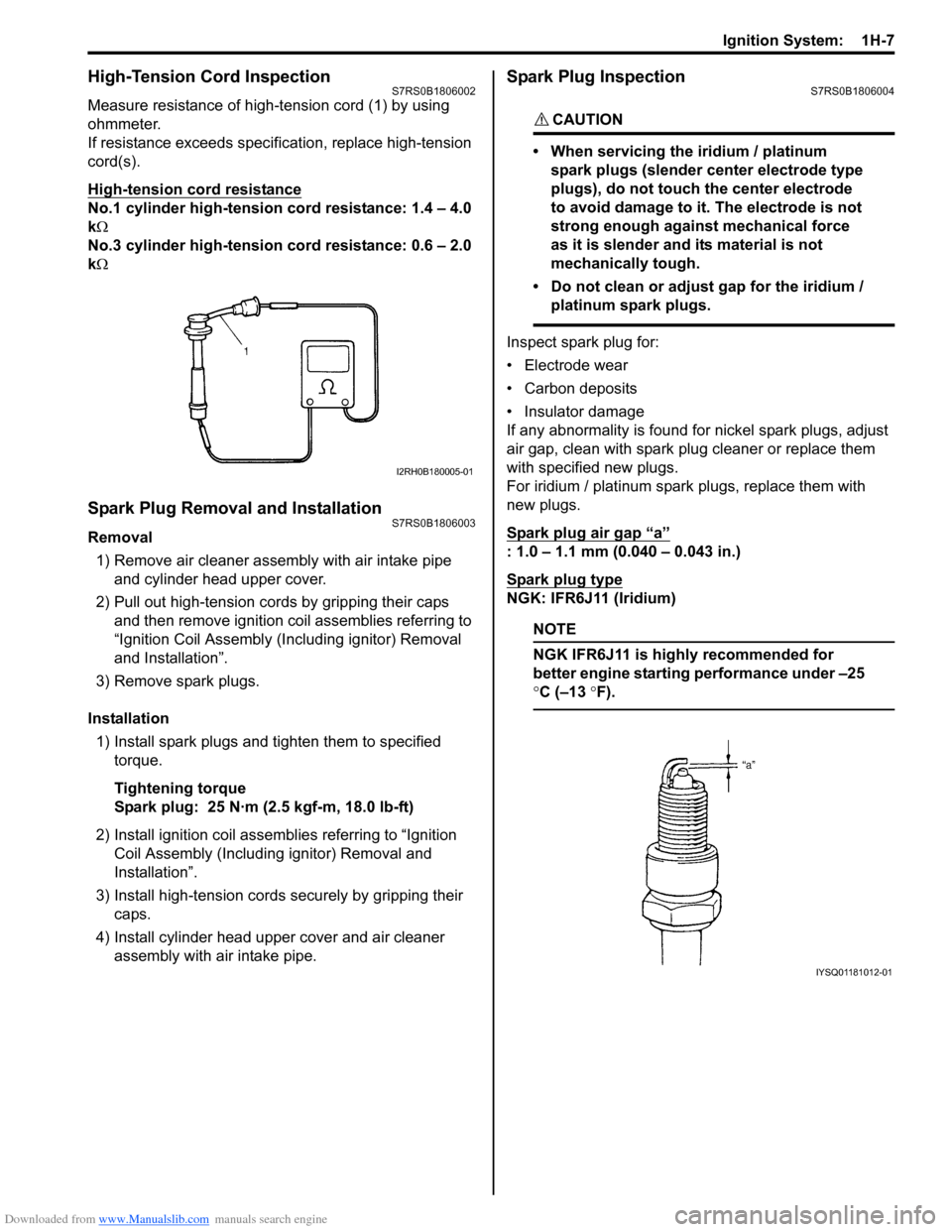
Measure resistance of high-tension cord (1) by using
ohmmeter.
If resistance exceeds specification, replace high-tension
cord(s).
High-tension cord resistance
No.1 cylinder high-tension cord resistance: 1.4 – 4.0
k Ω
No.3 cylinder high-tension cord resistance: 0.6 – 2.0
k Ω
Spark Plug Removal and InstallationS7RS0B1806003
Removal
1) Remove air cleaner assembly with air intake pipe and cylinder head upper cover.
2) Pull out high-tension cords by gripping their caps and then remove ignition coil assemblies referring to
“Ignition Coil Assembly (Inc luding ignitor) Removal
and Installation”.
3) Remove spark plugs.
Installation 1) Install spark plugs and tighten them to specified torque.
Tightening torque
Spark plug: 25 N·m (2.5 kgf-m, 18.0 lb-ft)
2) Install ignition coil assemblies referring to “Ignition Coil Assembly (Including ignitor) Removal and
Installation”.
3) Install high-tension cords securely by gripping their caps.
4) Install cylinder head upper cover and air cleaner assembly with air intake pipe.
Spark Plug InspectionS7RS0B1806004
CAUTION!
• When servicing the iridium / platinum
spark plugs (slender center electrode type
plugs), do not touch the center electrode
to avoid damage to it. The electrode is not
strong enough against mechanical force
as it is slender and its material is not
mechanically tough.
• Do not clean or adjust gap for the iridium / platinum spark plugs.
Inspect spark plug for:
• Electrode wear
• Carbon deposits
• Insulator damage
If any abnormality is found for nickel spark plugs, adjust
air gap, clean with spark plug cleaner or replace them
with specified new plugs.
For iridium / platinum spark plugs, replace them with
new plugs.
Spark plug air gap
“a”
: 1.0 – 1.1 mm (0.040 – 0.043 in.)
Spark plug type
NGK: IFR6J11 (Iridium)
NOTE
NGK IFR6J11 is highly recommended for
better engine starting performance under –25
°C (–13 °F).
I2RH0B180005-01
IYSQ01181012-01