Page 191 of 1496

Downloaded from www.Manualslib.com manuals search engine Engine General Information and Diagnosis: 1A-141
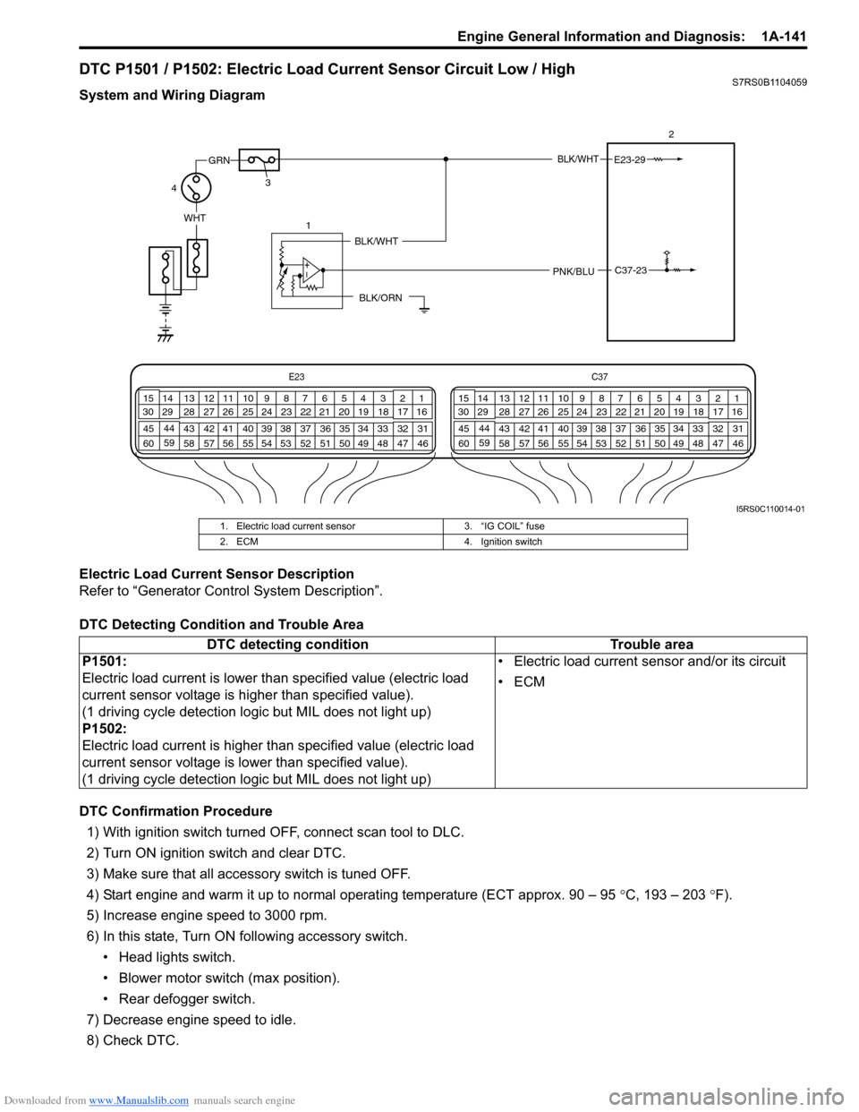
DTC P1501 / P1502: Electric Load Current Sensor Circuit Low / HighS7RS0B1104059
System and Wiring Diagram
Electric Load Current Sensor Description
Refer to “Generator Control System Description”.
DTC Detecting Condition and Trouble Area
DTC Confirmation Procedure1) With ignition switch turned OFF, connect scan tool to DLC.
2) Turn ON ignition switch and clear DTC.
3) Make sure that all accessory switch is tuned OFF.
4) Start engine and warm it up to normal operating temperature (ECT approx. 90 – 95 °C, 193 – 203 °F).
5) Increase engine speed to 3000 rpm.
6) In this state, Turn ON following accessory switch.
• Head lights switch.
• Blower motor switch (max position).
• Rear defogger switch.
7) Decrease engine speed to idle.
8) Check DTC.
E23 C37
34
1819
567
1011
17
20
47 46
495051
2122
52 16
25 9
24
14
29
55
57 54 53
59
60 58 2
262728
15
30
56 4832 31
34353637
40
42 39 38
44
45 43 41 331
1213
238
34
1819
567
1011
17
20
47 46
495051
2122
52 16
25 9
24
14
29
55
57 54 53
59
60 58 2
262728
15
30
56 4832 31
34353637
40
42 39 38
44
45 43 41 331
1213
238
BLK/WHT
WHT
GRN
4
3 2
E23-29
1
C37-23PNK/BLU
BLK/ORN
BLK/WHT
I5RS0C110014-01
1. Electric load current sensor
3. “IG COIL” fuse
2. ECM 4. Ignition switch
DTC detecting condition Trouble area
P1501:
Electric load current is lower th an specified value (electric load
current sensor voltage is higher than specified value).
(1 driving cycle detection logic but MIL does not light up)
P1502:
Electric load current is higher than specified value (electric load
current sensor voltage is lo wer than specified value).
(1 driving cycle detection logic but MIL does not light up) • Electric load current sensor and/or its circuit
•ECM
Page 413 of 1496

Downloaded from www.Manualslib.com manuals search engine Charging System: 1J-3
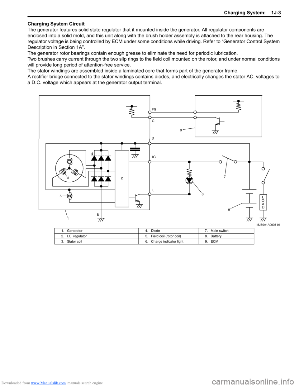
Charging System Circuit
The generator features solid state regulator that it mounted inside the generator. All regulator components are
enclosed into a solid mold, and this unit along with the brus h holder assembly is attached to the rear housing. The
regulator voltage is being controlled by ECM under some cond itions while driving. Refer to “Generator Control System
Description in Section 1A”.
The generator rotor bearings contain enough grease to eliminate the need for periodic lubrication.
Two brushes carry current through the two slip rings to the field coil mounted on the rotor, and under normal conditions
will provide long period of attention-free service.
The stator windings are assembled inside a laminate d core that forms part of the generator frame.
A rectifier bridge connected to the stator windings contains diodes, and electrically changes the stator AC. voltages to
a D.C. voltage which appears at the generator output terminal.
I5JB0A1A0005-01
1. Generator 4. Diode7. Main switch
2. I.C. regulator 5. Field coil (rotor coil)8. Battery
3. Stator coil 6. Charge indicator light9. ECM
Page 1206 of 1496

Downloaded from www.Manualslib.com manuals search engine 9A-35 Wiring Systems:
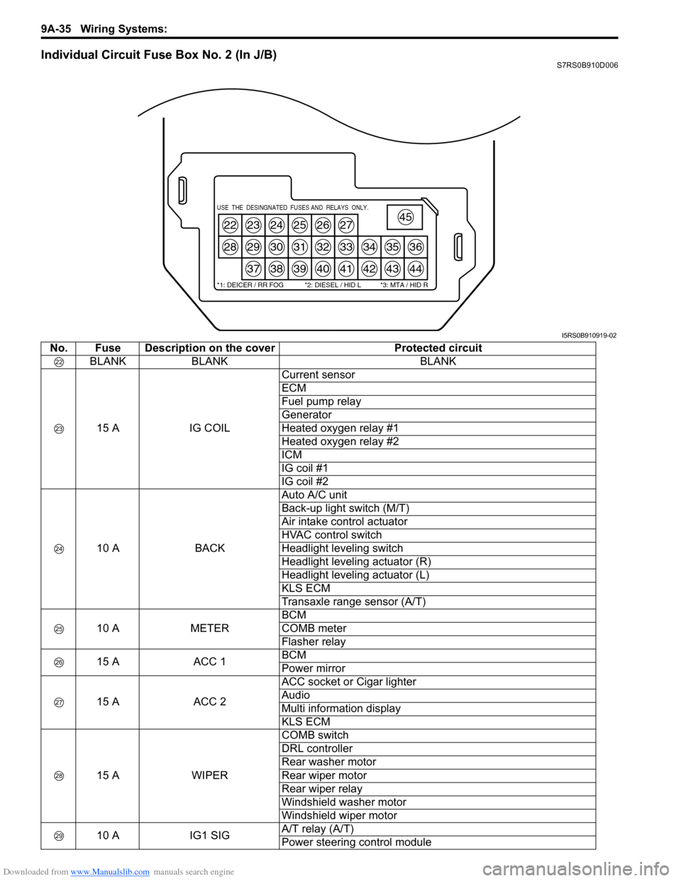
Individual Circuit Fuse Box No. 2 (In J/B)S7RS0B910D006
22
28
23
29
37
24
30
38
25
31
39
26
32
40
27
33
41
34
42
35
43
36
44
45USE THE DESINGNATED FUSES AND RELAYS ONLY.
*1: DEICER / RR FOG *2: DIESEL / HID L *3: MTA / HID R
I5RS0B910919-02
No. Fuse Description on the coverProtected circuit
BLANK BLANK BLANK
15 A IG COILCurrent sensor
ECM
Fuel pump relay
Generator
Heated oxygen relay #1
Heated oxygen relay #2
ICM
IG coil #1
IG coil #2
10 A BACKAuto A/C unit
Back-up light switch (M/T)
Air intake control actuator
HVAC control switch
Headlight leveling switch
Headlight leveling actuator (R)
Headlight leveling actuator (L)
KLS ECM
Transaxle range sensor (A/T)
10 A METERBCM
COMB meter
Flasher relay
15 A ACC 1BCM
Power mirror
15 A ACC 2ACC socket or Cigar lighter
Audio
Multi information display
KLS ECM
15 A WIPERCOMB switch
DRL controller
Rear washer motor
Rear wiper motor
Rear wiper relay
Windshield washer motor
Windshield wiper motor
10 A IG1 SIGA/T relay (A/T)
Power steering control module
Page 1420 of 1496

Downloaded from www.Manualslib.com manuals search engine 10B-17 Body Electrical Control System:
DTC B1133 (DTC No. 1133): Battery Voltage Too HighS7RS0BA204008
Wiring Diagram
Refer to “BCM Power Circuit and Ground Circuit Check”.
DTC Detecting Conditi on and Possible Cause
Flow Test Description
Step 1: Check charging system
DTC Troubleshooting 3
Power supply circuit check
1) Check for proper connection to junction block assembly
connector at terminals “G32-2” and “G32-5”.
2) If OK, turn ignition switch ON.
3) Measure voltage between following terminals. • Between “G32-2” terminal of junction block assembly connector and vehicle body ground
• Between “G32-5” terminal of junction block assembly connector and vehicle body ground
Is each voltage 10 – 14 V? Go to Step 4. Repair power supply
circuit.
4 Ground circuit check
1) Turn ignition switch to OFF position.
2) Check for proper connection to junction block assembly
connector at terminals “G33-3”, “G34-9” and “L05-4”.
3) If OK, then measure resistance between following terminals.
• Between “G33-3” terminal of junction block assembly connector and vehicle body ground
• Between “G34-9” terminal of junction block assembly connector and vehicle body ground
• Between “L05-4” terminal of junction block assembly connector and vehicle body ground
Is each resistance 2
Ω or less? BCM power supply
circuit and ground circuit
are in good condition.
Repair ground circuit.
Step Action Yes No
DTC detecting condition
Possible cause
Power voltage supplied from battery to BCM is
higher than 16V. • Charging system malfunction
• BCM malfunction
Step
Action YesNo
1 Charging system operation check
1) Check generator for operation referring to “Generator
Test (Overcharged Battery Check) in Section 1J”.
Is it in good condition? Substitute a known
good BCM (included in
junction block
assembly) and recheck.
Repair charging system.