2006 SUZUKI SWIFT fuel indicator
[x] Cancel search: fuel indicatorPage 469 of 1496

Downloaded from www.Manualslib.com manuals search engine Wheels and Tires: 2D-2
Lower than recommended pressure can cause:
• Tire squeal on turns
• Hard Steering
• Rapid and uneven wear on the edges of the tread
• Tire rim bruises and rupture
• Tire cord breakage
• High tire temperature
• Reduced handling
• High fuel consumption
Replacement Tires
When replacement is necessary, the original equipment
type tire should be used. Refer to the Tire Placard.
Replacement tires should be of the same size, load
range and construction as those originally on the vehicle.
Use of any other size or type tire may affect ride,
handling, speedometer / odometer calibration, vehicle
ground clearance and tire or snow chain clearance to the
body and chassis.
It is recommended that new tires be installed in pairs on
the same axle. If necessary to replace only one tire, it
should be paired with the tire having the most tread, to
equalize braking traction.
WARNING!
Do not mix different types of tires on the
same vehicle such as radial, bias and bias-
belted tires except in emergencies, because
handling may be seriously affected and may
result in loss of control.
The metric term for tire infl ation pressure is the kilo
pascal (kPa). Tire pressures is usually printed in both
kPa and kgf/cm
2 on the “Tire Placard”.
Metric tire gauges are available from tool suppliers.
The chart, shown the table, converts commonly used
inflation pressures from kPa to kgf/cm
2 and psi.
Wheels DescriptionS7RS0B2401002
Wheel Maintenance
Wheel repairs that use welding, heating, or peening are
not approved. All damaged wheels should be replaced.
Replacement Wheels
Wheels must be replaced if they are bent, dented, have
excessive lateral or radial runout, air leak through welds,
have elongated bolt holes, if lug wheel bolts won’t stay
tight, or if they are heavily rusted. Wheels with greater
runout than shown in the following may cause
objectional vibrations.
Replacement wheels must be equivalent to the original
equipment wheels in load capacity, diameter, rim with
offset and mounting configuration. A wheel of improper
size or type may affect wheel and bearing life, brake
cooling, speedometer / odometer calibration, vehicle
ground clearance and tire clearance to body and
chassis.
How to Measure Wheel Runout
To measure the wheel runout, it is necessary to use an
accurate dial indicator. The tire may be on or off the
wheel. The wheel should be installed to the wheel
balancer of the like for proper measurement.
Take measurements of both lateral runout “a” and radial
runout “b” at both inside an d outside of the rim flange.
With the dial indicator set in place securely, turn the
wheel one full revolution slowly and record every reading
of the indicator.
When the measured runout exceeds the specification
and correction by the balancer adjustment is impossible,
replace the wheel. If the reading is affected by welding,
paint or scratch, it should be ignored.
Lateral runout limit “a”
: 0.3 mm (0.012 in.)
Radial runout limit “b”
: 0.3 mm (0.012 in.)
kPa kgf/cm2psi
Conversion: 1 psi =
6.895 kPa 1 kgf/cm
2 =
98.066 kPa 160 1.6 23
180 1.8 26
200 2.0 29
220 2.2 32
240 2.4 35
260 2.6 38
280 2.8 41
300 3.0 44
I4RS0A240001-01
Page 670 of 1496
Downloaded from www.Manualslib.com manuals search engine 5A-26 Automatic Transmission/Transaxle:
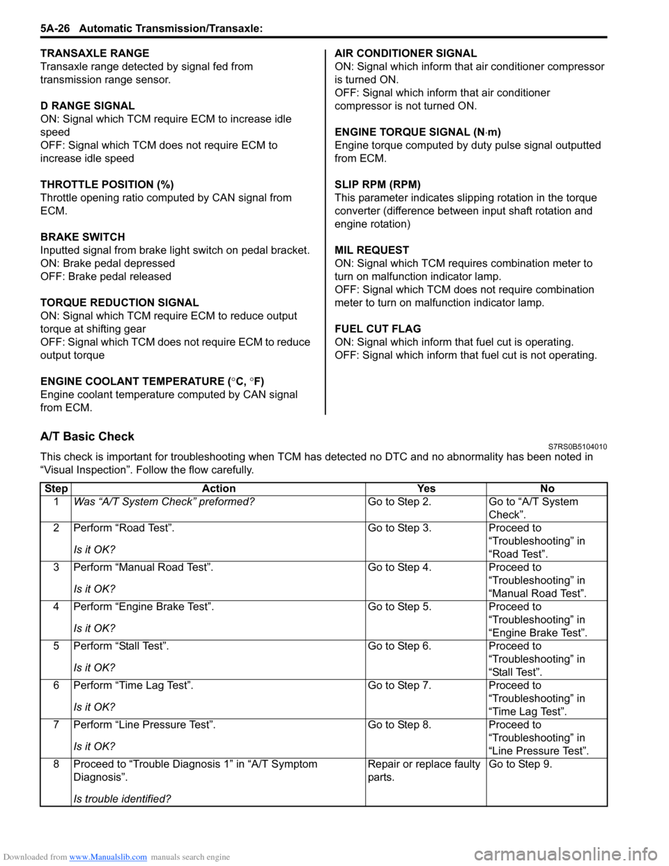
TRANSAXLE RANGE
Transaxle range detected by signal fed from
transmission range sensor.
D RANGE SIGNAL
ON: Signal which TCM require ECM to increase idle
speed
OFF: Signal which TCM does not require ECM to
increase idle speed
THROTTLE POSITION (%)
Throttle opening ratio computed by CAN signal from
ECM.
BRAKE SWITCH
Inputted signal from brake light switch on pedal bracket.
ON: Brake pedal depressed
OFF: Brake pedal released
TORQUE REDUCTION SIGNAL
ON: Signal which TCM require ECM to reduce output
torque at shifting gear
OFF: Signal which TCM does not require ECM to reduce
output torque
ENGINE COOLANT TEMPERATURE ( °C, °F)
Engine coolant temperature computed by CAN signal
from ECM. AIR CONDITIONER SIGNAL
ON: Signal which inform that air conditioner compressor
is turned ON.
OFF: Signal which inform that air conditioner
compressor is not turned ON.
ENGINE TORQUE SIGNAL (N
⋅m)
Engine torque computed by duty pulse signal outputted
from ECM.
SLIP RPM (RPM)
This parameter indicates slip ping rotation in the torque
converter (difference between input shaft rotation and
engine rotation)
MIL REQUEST
ON: Signal which TCM requires combination meter to
turn on malfunction indicator lamp.
OFF: Signal which TCM does not require combination
meter to turn on malf unction indicator lamp.
FUEL CUT FLAG
ON: Signal which inform that fuel cut is operating.
OFF: Signal which inform that fuel cut is not operating.
A/T Basic CheckS7RS0B5104010
This check is important for troubleshooting when TCM has detected no DTC and no abnormality has been noted in
“Visual Inspection”. Fo llow the flow carefully.
Step Action YesNo
1 Was “A/T System Check” preformed? Go to Step 2.Go to “A/T System
Check”.
2 Perform “Road Test”.
Is it OK? Go to Step 3.
Proceed to
“Troubleshooting” in
“Road Test”.
3 Perform “Manual Road Test”.
Is it OK? Go to Step 4.
Proceed to
“Troubleshooting” in
“Manual Road Test”.
4 Perform “Engine Brake Test”.
Is it OK? Go to Step 5.
Proceed to
“Troubleshooting” in
“Engine Brake Test”.
5 Perform “Stall Test”.
Is it OK? Go to Step 6.
Proceed to
“Troubleshooting” in
“Stall Test”.
6 Perform “Time Lag Test”.
Is it OK? Go to Step 7.
Proceed to
“Troubleshooting” in
“Time Lag Test”.
7 Perform “Line Pressure Test”.
Is it OK? Go to Step 8.
Proceed to
“Troubleshooting” in
“Line Pressure Test”.
8 Proceed to “Trouble Diag nosis 1” in “A/T Symptom
Diagnosis”.
Is trouble identified? Repair or replace faulty
parts.
Go to Step 9.
Page 1168 of 1496

Downloaded from www.Manualslib.com manuals search engine 9-ii Table of Contents
List of Connectors ........................................... 9A-103
C Connector .................................................... 9A-103
D Connector (M16A engine) ........................... 9A-104
E Connector .................................................... 9A-104
G Connector .................................................... 9A-106
J Connector ..................................................... 9A-108
K Connector .................................................... 9A-109
L Connector..................................................... 9A-109
M Connector (SPORT model) ......................... 9A-111
O Connector .................................................... 9A-111
R Connector .................................................... 9A-111
Lighting Systems .................................... 9B-1
Component Location ........... ................................9B-1
Lighting System Component s Location............... 9B-1
Interior Light System Location............................. 9B-2
Diagnostic Information and Procedures ............ 9B-2 Headlight Symptom Diagnosis ............................ 9B-2
Headlight Leveling System Symptom Diagnosis (If Equipped) ..................................... 9B-2
Turn Signal and Hazard Warning Light Symptom Diagnosis .......................................... 9B-3
Clearance, Tail and License Plate Light Symptom Diagnosis .......................................... 9B-3
Back-Up Light Symptom Diagnosis..................... 9B-4
Brake Light Symptom Diagnosis ......................... 9B-4
Front Fog Light Symptom Diagnosis (If Equipped) .......................................................... 9B-4
Interior Light Symptom Diagnosis ....................... 9B-5
Repair Instructions ..............................................9B-5 Headlight Housing Removal and Installation ...... 9B-5
Headlight Bulb Replacemen t............................... 9B-6
Headlight Aiming Adjustment with Screen .......... 9B-6
Headlight Switch (in Lighting Switch) Removal and Installation ................................... 9B-8
Headlight Switch (in Lighting Switch) Inspection .......................................................... 9B-8
Hazard Warning Switch Removal and Installation ......................................................... 9B-8
Hazard Warning Switch Inspection ..................... 9B-9
Brake Light Switch Inspection ............................. 9B-9
Turn Signal Light Switch (in Lighting Switch) Removal and Installation ................................... 9B-9
Turn Signal Light Switch (in Lighting Switch) Inspection .......................................................... 9B-9
Turn Signal and Hazard Warning Relay Removal and Installation ................................... 9B-9
Turn Signal and Hazard Warning Relay Inspection ........................................................ 9B-10
License Light Removal and Installation............. 9B-10
Front Fog Light Removal and Installation (If Equipped) ........................................................ 9B-11
Front Fog Light Bulb Replacement (If Equipped) ........................................................ 9B-11
Front Fog Light Switch Inspection (If Equipped) ........................................................ 9B-11
Front Fog Light Relay Inspection (If Equipped) ........................................................ 9B-11
Front Fog Light Aiming Adjustment with Screen (If Equipped) ....................................... 9B-12 Headlight Leveling Switch Inspection (If
Equipped) ........................................................ 9B-13
Headlight Leveling Actuator Inspection (If Equipped) ........................................................ 9B-13
Instrumentation / Driver Info. / Horn ...... 9C-1
Precautions ...........................................................9C-1 Precautions in Diagnosing Troubles for Combination Meter ............................................9C-1
General Description .............................................9C-1 CAN Communication System Description...........9C-1
Auto Volume Co ntrol System Description (If
Equipped) ..........................................................9C-3
Schematic and Routing Diagram ........................9C-4 Combination Meter Circuit Diagram ....................9C-4
Component Location ............ ...............................9C-6
Audio System Component Location ....................9C-6
Diagnostic Information and Procedures ............9C-6 Speedometer and VSS Symp tom Diagnosis ......9C-6
Tachometer Symptom Diagnosis ........................9C-6
Engine Coolant Temperature (ECT) Meter Symptom Diagnosis ..........................................9C-7
Fuel Meter Symptom Diagnosis ..........................9C-7
Low Fuel Warning Light Symptom Diagnosis .....9C-7
Oil Pressure Warning Light Symptom Diagnosis ..........................................................9C-8
Brake and Parking Brake Warning Light Symptom Diagnosis ..........................................9C-8
Seat Belt Reminder Light Symptom Diagnosis (If Equipped)......................................................9C-8
A/T Shift Position Indicator Symptom Diagnosis (A/T Model).......................................9C-9
Charge Warning Light Sy mptom Diagnosis ........9C-9
Main Beam (High Beam) Indicator Symptom Diagnosis ..........................................................9C-9
Warning Buzzer Circuit Sy mptom Diagnosis ....9C-10
Cigarette Lighter Symptom Diagnosis (If Equipped) ........................................................9C-10
Horn Symptom Diagnosis .................................9C-10
Information Display Symptom Diagnosis (If Equipped) ........................................................9C-11
Clock Symptom Diagnosis (If Equipped)...........9C-12
Audio System Symptom Diagnosis (If Equipped) ........................................................9C-12
Remote Audio Control Switch Symptom Diagnosis (If Equipped) ...................................9C-13
Navigation Symptom Diagnosis (If Equipped)...9C-14
Repair Instructions ............ ................................9C-14
Ignition Switch Removal and Installation...........9C-14
Ignition Switch Inspection..................................9C-14
Combination Meter Removal and Installation ...9C-15
Fuel Level Sensor Removal and Installation .....9C-15
Fuel Level Sensor Inspection ............................9C-15
Oil Pressure Switch Remova l and Installation ..9C-15
Oil Pressure Switch Inspec tion .........................9C-16
Engine Coolant Temperature (ECT) Sensor Inspection ........................................................9C-16
Brake Fluid Level Switch Inspection .................9C-16
Parking Brake Switch Inspec tion.......................9C-16
Page 1296 of 1496
Downloaded from www.Manualslib.com manuals search engine 9C-1 Instrumentation / Driver Info. / Horn:
Body, Cab and Accessories
Instrumentation / Driver Info. / Horn
Precautions
Precautions in Diagnosing Troubles for Combination MeterS7RS0B9300001
Combination meter uses signals (information) from each control module by CAN communication to control
speedometer, tachometer, engine coolant temp meter, warning light and indicator light (other than air bag warning
light, high beam indicator light, EPS warn ing light and turn signal indicator light). Therefore, check that no DTC is
detected in each module before performing combination me ter symptom diagnosis. If any DTC is detected, correct
trouble indicated by that DTC troubleshooting first.
General Description
CAN Communication System DescriptionS7RS0B9301001
Refer to “CAN Communication System Description in Section 1A” for Can communication system description.
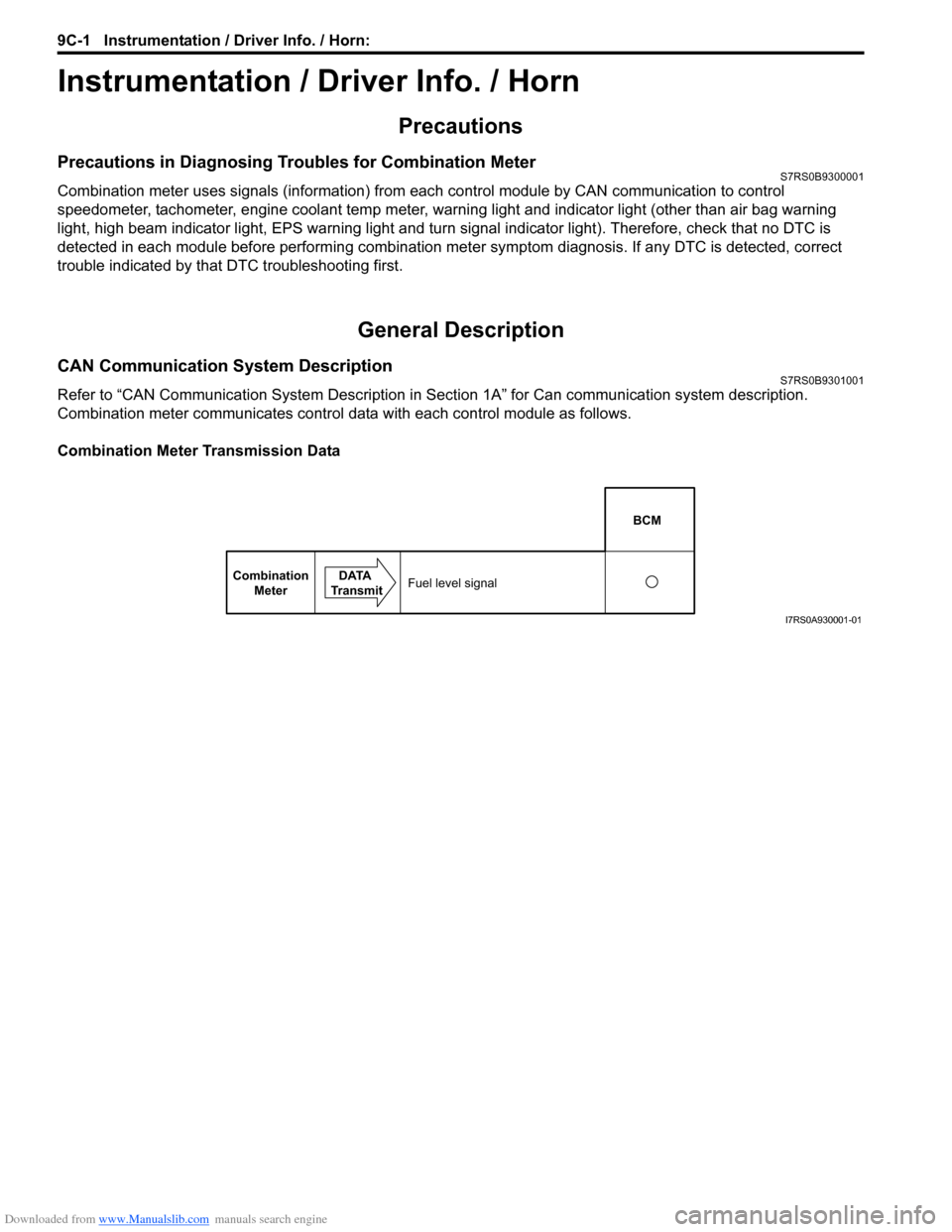
Combination meter communicates control data with each control module as follows.
Combination Meter Transmission Data
BCM
Combination Meter DATA
TransmitFuel level signal
I7RS0A930001-01
Page 1299 of 1496
Downloaded from www.Manualslib.com manuals search engine Instrumentation / Driver Info. / Horn: 9C-4
Schematic and Routing Diagram
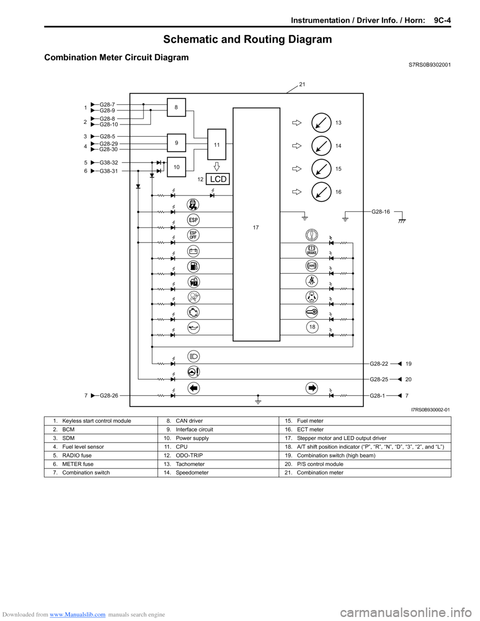
Combination Meter Circuit DiagramS7RS0B9302001
16
15
14
13
G28-5
5
6
3
G28-26
7
G28-2219
G28-2520
G28-17
12
10 11
21
9
17
G28-304G28-29
18
G28-16
G28-9
G28-10G28-8 G28-7
1
2 8
G38-31
G38-32
I7RS0B930002-01
1. Keyless start control module
8. CAN driver 15. Fuel meter
2. BCM 9. Interface circuit 16. ECT meter
3. SDM 10. Power supply 17. Stepper motor and LED output driver
4. Fuel level sensor 11. CPU 18. A/T shift position indicator (“P”, “R”, “N”, “D”, “3”, “2”, and “L”)
5. RADIO fuse 12. ODO-TRIP 19. Combination switch (high beam)
6. METER fuse 13. Tachometer 20. P/S control module
7. Combination switch 14. Speedometer 21. Combination meter
Page 1416 of 1496
Downloaded from www.Manualslib.com manuals search engine 10B-13 Body Electrical Control System:
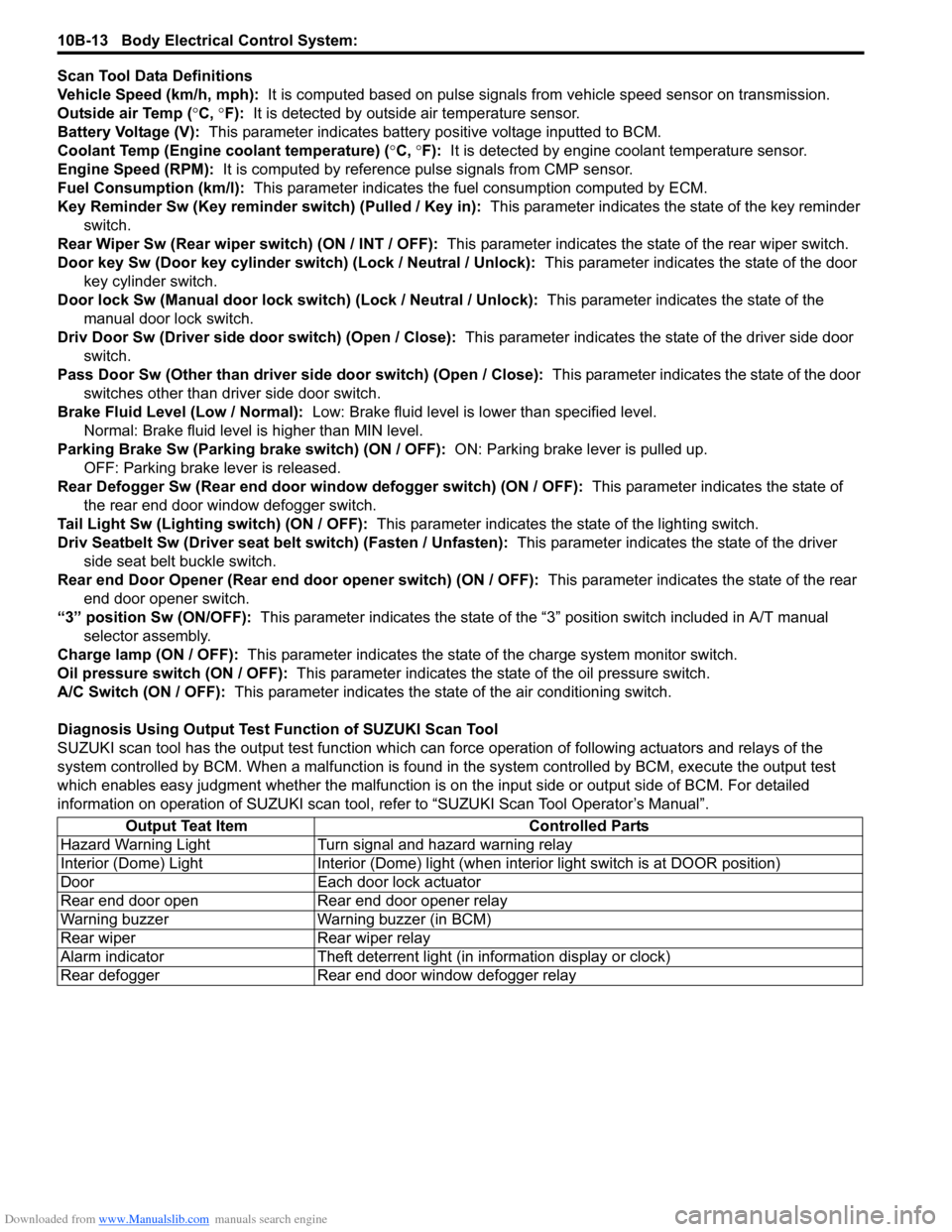
Scan Tool Data Definitions
Vehicle Speed (km/h, mph): It is computed based on pulse signals from vehicle speed sensor on transmission.
Outside air Temp ( °C, °F): It is detected by outside air temperature sensor.
Battery Voltage (V): This parameter indicates battery po sitive voltage inputted to BCM.
Coolant Temp (Engine coolant temperature) ( °C, °F): It is detected by engine coolant temperature sensor.
Engine Speed (RPM): It is computed by reference pulse signals from CMP sensor.
Fuel Consumption (km/l): This parameter indicates the fuel consumption computed by ECM.
Key Reminder Sw (Key reminder switch) (Pulled / Key in): This parameter indicates the state of the key reminder
switch.
Rear Wiper Sw (Rear wiper switch) (ON / INT / OFF): This parameter indicates the state of the rear wiper switch.
Door key Sw (Door key cylinder switch) (Lock / Neutral / Unlock): This parameter indicates the state of the door
key cylinder switch.
Door lock Sw (Manual door lock switch) (Lock / Neutral / Unlock): This parameter indicates the state of the
manual door lock switch.
Driv Door Sw (Driver side d oor switch) (Open / Close): This parameter indicates the state of the driver side door
switch.
Pass Door Sw (Other than driver side door switch) (Open / Close): This parameter indicates the state of the door
switches other than driver side door switch.
Brake Fluid Level (Low / Normal): Low: Brake fluid level is lower than specified level.
Normal: Brake fluid level is higher than MIN level.
Parking Brake Sw (Parking brake switch) (ON / OFF): ON: Parking brake lever is pulled up.
OFF: Parking brake lever is released.
Rear Defogger Sw (Rear end door window defogger switch) (ON / OFF): This parameter indicates the state of
the rear end door window defogger switch.
Tail Light Sw (Lighting switch) (ON / OFF): This parameter indicates the state of the lighting switch.
Driv Seatbelt Sw (Driver seat belt switch) (Fasten / Unfasten): This parameter indicates the state of the driver
side seat belt buckle switch.
Rear end Door Opener (Rear end door opener switch) (ON / OFF): This parameter indicates the state of the rear
end door opener switch.
“3” position Sw (ON/OFF): This parameter indicates the state of the “3 ” position switch included in A/T manual
selector assembly.
Charge lamp (ON / OFF): This parameter indicates the state of the charge system monitor switch.
Oil pressure switch (ON / OFF): This parameter indicates the state of the oil pressure switch.
A/C Switch (ON / OFF): This parameter indicates the state of the air conditioning switch.
Diagnosis Using Output Test Function of SUZUKI Scan Tool
SUZUKI scan tool has the output test function which can force operation of following actuators and relays of the
system controlled by BCM. When a malf unction is found in the system controlled by BCM, execute the output test
which enables easy judgment whether the malfunction is on the input side or output side of BCM. For detailed
information on operation of SUZUKI scan tool, refer to “SUZUKI Scan Tool Operator’s Manual”.
Output Teat Item Controlled Parts
Hazard Warning Light Turn signal and hazard warning relay
Interior (Dome) Light Interior (Dome) light (wh en interior light switch is at DOOR position)
Door Each door lock actuator
Rear end door open Rear end door opener relay
Warning buzzer Warning buzzer (in BCM)
Rear wiper Rear wiper relay
Alarm indicator Theft deterrent light (in information display or clock)
Rear defogger Rear end door window defogger relay
Page 1445 of 1496
Downloaded from www.Manualslib.com manuals search engine Immobilizer Control System: 10C-2
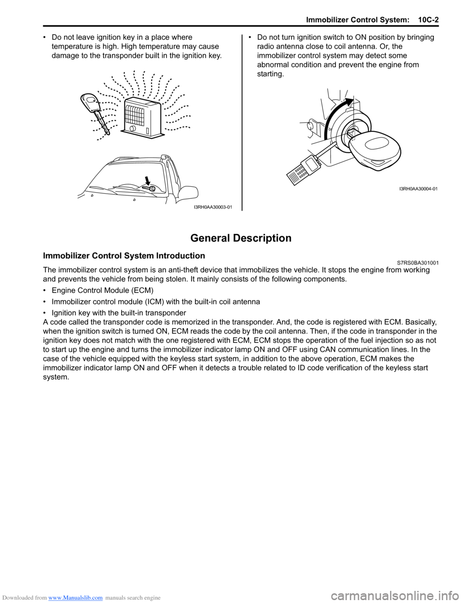
• Do not leave ignition key in a place where
temperature is high. High temperature may cause
damage to the transponder built in the ignition key. • Do not turn ignition switch to ON position by bringing
radio antenna close to coil antenna. Or, the
immobilizer control syst em may detect some
abnormal condition and prevent the engine from
starting.
General Description
Immobilizer Control System IntroductionS7RS0BA301001
The immobilizer control system is an anti-theft device that immobilizes the vehicle. It stops the engine from working
and prevents the vehicle from being stolen. It mainly consists of the following components.
• Engine Control Module (ECM)
• Immobilizer control module (ICM) with the built-in coil antenna
• Ignition key with the built-in transponder
A code called the transponder code is memorized in the tran sponder. And, the code is registered with ECM. Basically,
when the ignition switch is turned ON, ECM reads the code by the coil antenna. Then, if the code in transponder in the
ignition key does not match with the one registered with ECM, ECM stops the operati on of the fuel injection so as not
to start up the engine and turns the immobilizer indi cator lamp ON and OFF using CA N communication lines. In the
case of the vehicle equipped with the keyless start system , in addition to the above operation, ECM makes the
immobilizer indicator lamp ON and OFF when it detects a trouble related to ID code verification of the keyless start
system.
I3RH0AA30003-01
I3RH0AA30004-01