2006 SUZUKI SWIFT camshaft installation
[x] Cancel search: camshaft installationPage 162 of 1496

Downloaded from www.Manualslib.com manuals search engine 1A-112 Engine General Information and Diagnosis:
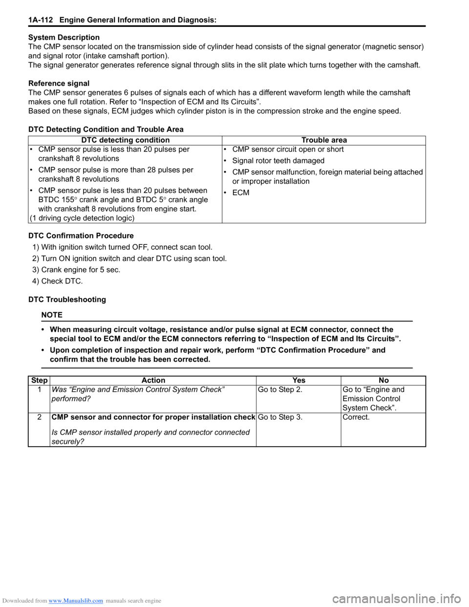
System Description
The CMP sensor located on the transmission side of cylinder head consists of the signal generator (magnetic sensor)
and signal rotor (intake camshaft portion).
The signal generator generates reference signal through slits in the slit plate which turns together with the camshaft.
Reference signal
The CMP sensor generates 6 pulses of si gnals each of which has a different waveform length while the camshaft
makes one full rotation. Refer to “Inspection of ECM and Its Circuits”.
Based on these signals, ECM judges which cylinder pist on is in the compression stroke and the engine speed.
DTC Detecting Condition and Trouble Area
DTC Confirmation Procedure 1) With ignition switch turned OFF, connect scan tool.
2) Turn ON ignition switch and clear DTC using scan tool.
3) Crank engine for 5 sec.
4) Check DTC.
DTC Troubleshooting
NOTE
• When measuring circuit voltage, resistance and/ or pulse signal at ECM connector, connect the
special tool to ECM and/or the ECM connectors re ferring to “Inspection of ECM and Its Circuits”.
• Upon completion of inspection and repair work, perform “DTC Confirmation Procedure” and confirm that the trouble has been corrected.
DTC detecting condition Trouble area
• CMP sensor pulse is less than 20 pulses per crankshaft 8 revolutions
• CMP sensor pulse is more than 28 pulses per crankshaft 8 revolutions
• CMP sensor pulse is less than 20 pulses between BTDC 155 ° crank angle and BTDC 5 ° crank angle
with crankshaft 8 revolutions from engine start.
(1 driving cycle detection logic) • CMP sensor circuit open or short
• Signal rotor teeth damaged
• CMP sensor malfunction, foreign material being attached
or improper installation
•ECM
Step Action YesNo
1 Was “Engine and Emission Control System Check”
performed? Go to Step 2.
Go to “Engine and
Emission Control
System Check”.
2 CMP sensor and connector for proper installation check
Is CMP sensor installed properly and connector connected
securely? Go to Step 3.
Correct.
Page 280 of 1496

Downloaded from www.Manualslib.com manuals search engine 1C-8 Engine Electrical Devices:
Installation
Reverse removal procedure noting the following.
• Tighten heated oxygen sensor to specified torque.Tightening torque
Heated oxygen sensor (a): 45 N·m (4.5 kgf-m,
32.5 lb-ft)
• Install exhaust manifold referring to “Exhaust Manifold Removal and Installation in Section 1K”, if removed.
• Connect connector of heated oxygen sensor and clamp wire harness securely.
• After installing heated oxygen sensor, start engine and check that no exhaust gas leakage exists.
CMP Sensor Removal and InstallationS7RS0B1306012
Removal
1) Disconnect negative (–) cable at battery.
2) Disconnect connector from CMP sensor.
3) Remove CMP sensor from cylinder head.
Installation 1) Install CMP sensor to cylinder head.
Tightening torque
CMP sensor bolt (a): 10 N·m (1.0 kgf-m, 7.5 lb-ft)
2) Connect connector to CMP sensor securely.
3) Connect negative (–) cable to battery.
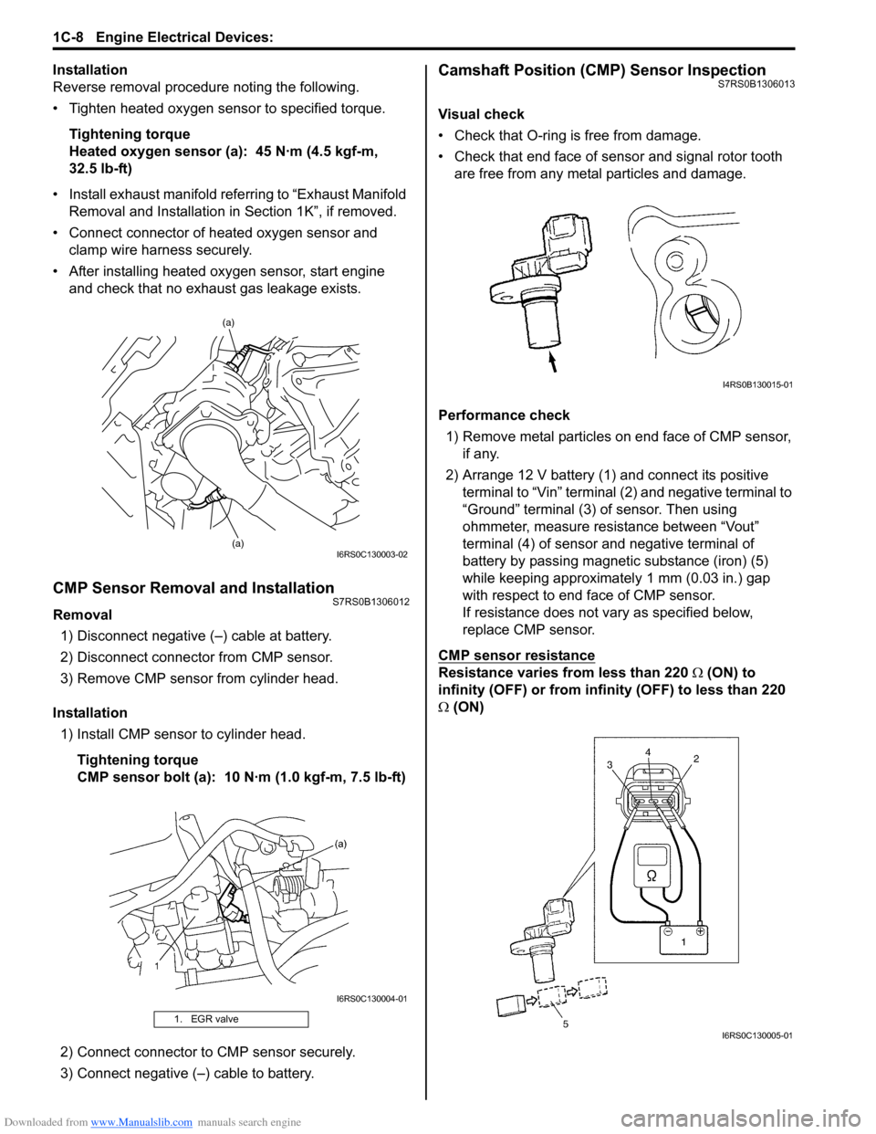
Camshaft Position (CMP) Sensor InspectionS7RS0B1306013
Visual check
• Check that O-ring is free from damage.
• Check that end face of sensor and signal rotor tooth are free from any metal particles and damage.
Performance check 1) Remove metal particles on end face of CMP sensor, if any.
2) Arrange 12 V battery (1) and connect its positive terminal to “Vin” terminal (2) and negative terminal to
“Ground” terminal (3) of sensor. Then using
ohmmeter, measure resistance between “Vout”
terminal (4) of sensor and negative terminal of
battery by passing magnetic substance (iron) (5)
while keeping approximately 1 mm (0.03 in.) gap
with respect to end face of CMP sensor.
If resistance does not vary as specified below,
replace CMP sensor.
CMP sensor resistance
Resistance varies from less than 220 Ω (ON) to
infinity (OFF) or from infinity (OFF) to less than 220
Ω (ON)
1. EGR valve
(a)
(a)
I6RS0C130003-02
I6RS0C130004-01
I4RS0B130015-01
I6RS0C130005-01
Page 291 of 1496

Downloaded from www.Manualslib.com manuals search engine Engine Mechanical: 1D-6
6) Connect special tool (Vacuum gauge) to PCV hose (1).
Special tool
(A): 09915–67311
7) Blind PCV valve (2) using tape (3) or the like.
8) Install air cleaner assembly and air suction hose referring to “Air Cleaner Components”.
9) Run engine at specified idle speed and read vacuum gauge. Vacuum should be within specification.
Vacuum specification (at sea level)
59 – 73 kPa (45 – 55 cmHg, 17.7 – 21.6 in.Hg) at
specified idle speed
10) Remove air cleaner assembly and air suction hose referring to “Air Cleaner Components”.
11) Disconnect special tool (vacuum gage) from PCV valve.
12) Detach blind cap from PCV valve, and connect PCV hose to PCV valve.
13) Install air cleaner assembly and air suction hose referring to “Air Cleaner Components”.
14) Install engine cover.
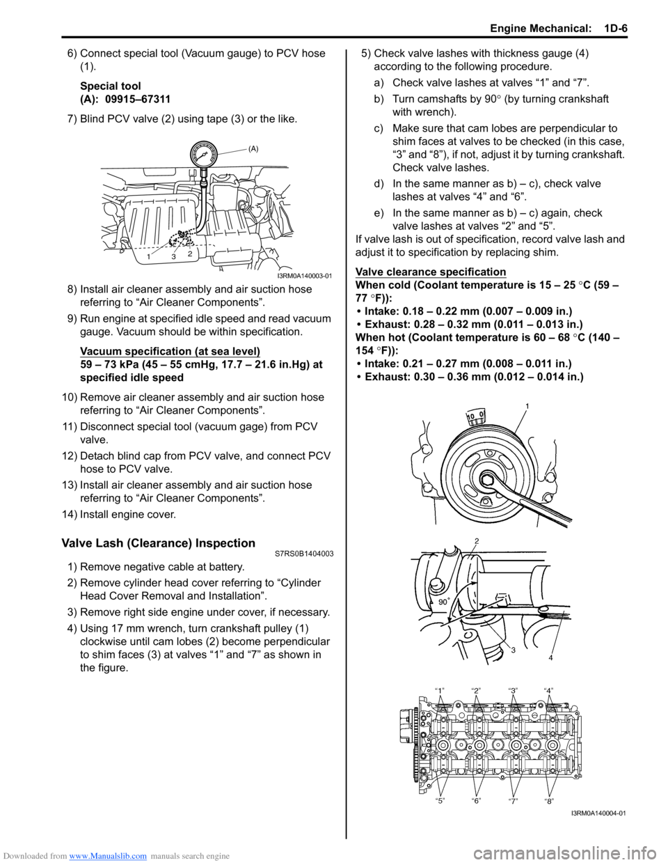
Valve Lash (Clearance) InspectionS7RS0B1404003
1) Remove negative cable at battery.
2) Remove cylinder head cover referring to “Cylinder Head Cover Removal and Installation”.
3) Remove right side engine under cover, if necessary.
4) Using 17 mm wrench, turn crankshaft pulley (1) clockwise until cam lobes (2) become perpendicular
to shim faces (3) at valves “1” and “7” as shown in
the figure. 5) Check valve lashes with thickness gauge (4)
according to the following procedure.
a) Check valve lashes at valves “1” and “7”.
b) Turn camshafts by 90 ° (by turning crankshaft
with wrench).
c) Make sure that cam lobes are perpendicular to shim faces at valves to be checked (in this case,
“3” and “8”), if not, adjust it by turning crankshaft.
Check valve lashes.
d) In the same manner as b) – c), check valve
lashes at valves “4” and “6”.
e) In the same manner as b) – c) again, check valve lashes at valves “2” and “5”.
If valve lash is out of specification, record valve lash and
adjust it to specification by replacing shim.
Valve clearance specification
When cold (Coolant te mperature is 15 – 25 °C (59 –
77 °F)):
• Intake: 0.18 – 0.22 mm (0.007 – 0.009 in.)
• Exhaust: 0.28 – 0.32 mm (0.011 – 0.013 in.)
When hot (Coolant temperature is 60 – 68 °C (140 –
154 °F)):
• Intake: 0.21 – 0.27 mm (0.008 – 0.011 in.)
• Exhaust: 0.30 – 0.36 mm (0.012 – 0.014 in.)
(A)
13 2
I3RM0A140003-01
I3RM0A140004-01
Page 293 of 1496

Downloaded from www.Manualslib.com manuals search engine Engine Mechanical: 1D-8
For example of intake side:
When thickness of removed shim is 2.40 mm (0.094
in.), and measured valve clearance is 0.45 mm
(0.018 in.).
A = 2.40 mm (0.094 in.) + 0.45 mm (0.018 in.) – 0.20
mm (0.008 in.) = 2.65 mm (0.104 in.)
Calculated thickness of new shim = 2.65 mm (0.104
in.)
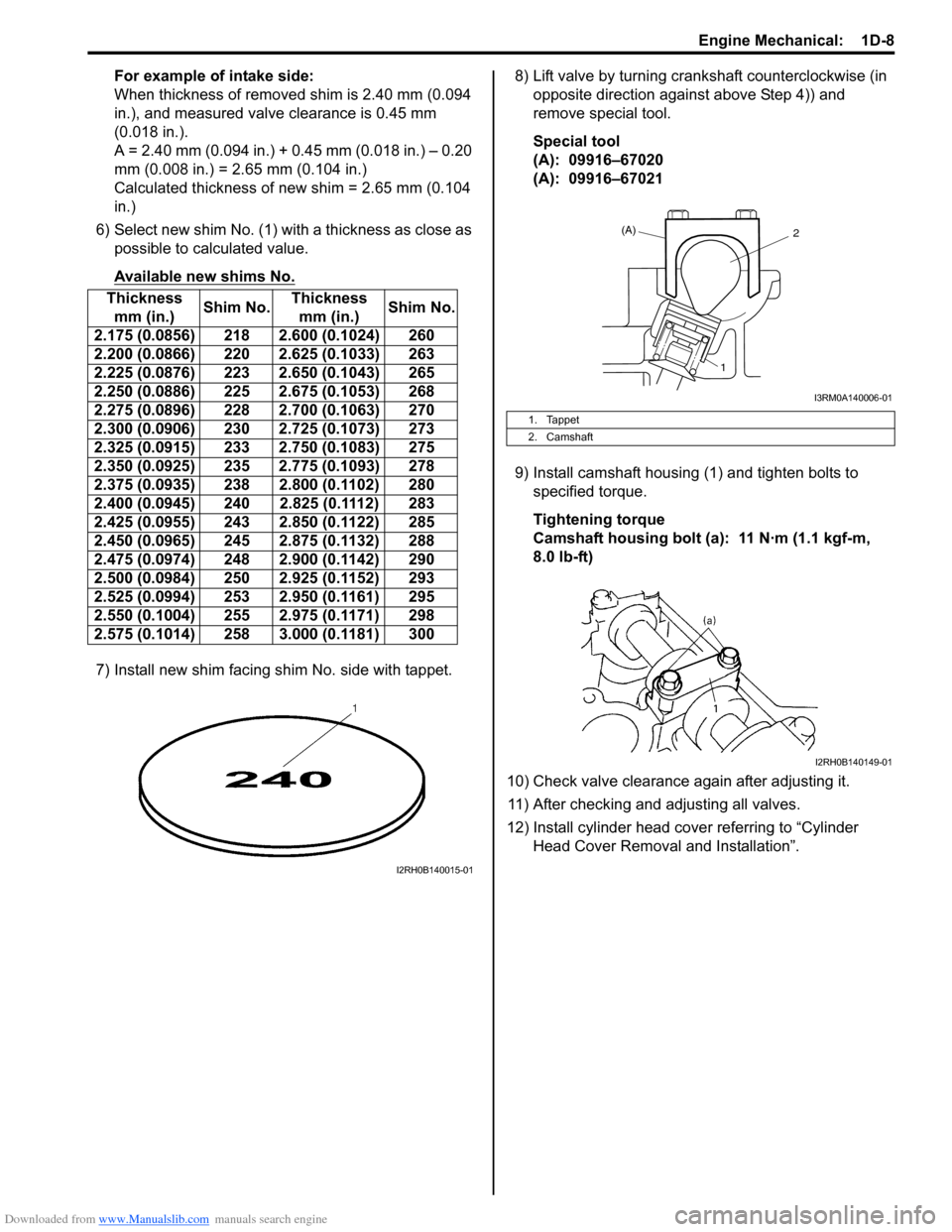
6) Select new shim No. (1) with a thickness as close as possible to calculated value.
Available new shims No.
7) Install new shim facing shim No. side with tappet. 8) Lift valve by turning crankshaft counterclockwise (in
opposite direction against above Step 4)) and
remove special tool.
Special tool
(A): 09916–67020
(A): 09916–67021
9) Install camshaft housing (1) and tighten bolts to specified torque.
Tightening torque
Camshaft housing bolt (a ): 11 N·m (1.1 kgf-m,
8.0 lb-ft)
10) Check valve clearance again after adjusting it. 11) After checking and adjusting all valves.
12) Install cylinder head cover referring to “Cylinder Head Cover Removal and Installation”.
Thickness
mm (in.) Shim No.Thickness
mm (in.) Shim No.
2.175 (0.0856) 218 2.600 (0.1024) 260
2.200 (0.0866) 220 2.625 (0.1033) 263
2.225 (0.0876) 223 2.650 (0.1043) 265
2.250 (0.0886) 225 2.675 (0.1053) 268
2.275 (0.0896) 228 2.700 (0.1063) 270
2.300 (0.0906) 230 2.725 (0.1073) 273
2.325 (0.0915) 233 2.750 (0.1083) 275
2.350 (0.0925) 235 2.775 (0.1093) 278
2.375 (0.0935) 238 2.800 (0.1102) 280
2.400 (0.0945) 240 2.825 (0.1112) 283
2.425 (0.0955) 243 2.850 (0.1122) 285
2.450 (0.0965) 245 2.875 (0.1132) 288
2.475 (0.0974) 248 2.900 (0.1142) 290
2.500 (0.0984) 250 2.925 (0.1152) 293
2.525 (0.0994) 253 2.950 (0.1161) 295
2.550 (0.1004) 255 2.975 (0.1171) 298
2.575 (0.1014) 258 3.000 (0.1181) 300
I2RH0B140015-01
1. Tappet
2. Camshaft
(A)2
1
I3RM0A140006-01
I2RH0B140149-01
Page 310 of 1496

Downloaded from www.Manualslib.com manuals search engine 1D-25 Engine Mechanical:
Timing Chain and Chain Tensioner Removal
and Installation
S7RS0B1406018
Removal
CAUTION!
After timing chain is removed, never turn
crankshaft and camshafts independently
more than its allowable turning range
described in “Installation”.
If turned, interferen ce may occur between
piston and valves and valves themselves,
and parts related to piston and valves may be
damaged.
1) Remove timing chain cover referring to “Timing Chain Cover Removal and Installation”.
2) By turning crankshaft, align camshafts and crankshaft at specific position as follows.
a) Align both intake and exhaust camshaft timing sprocket marks (1) with notches (2) of cylinder
head respectively.
b) Align crankshaft sprocket key (3) with notch of cylinder block (4).
Position crankshaft sprocke t key (3) at upside of
crankshaft as shown in figure.
3) Remove timing chain tensioner adjuster assembly (5).
4) Remove timing chain tensioner (6).
5) Remove timing chain No.1 guide (7).
6) Remove timing chain (8) with crankshaft timing sprocket (9). Installation
CAUTION!
After timing chain is removed, never turn
crankshaft and camshafts independently
more than such an extent (“a”, “b”) as shown
in figure.
If turned, interferen
ce may occur between
piston and valves and valves themselves,
and parts related to piston and valves may be
damaged.
1) Check that match marks (1) on intake and exhaust camshaft timing sprockets are in match with notches
(2) on cylinder head as shown in figure.
2) Set key (3) and turn crankshaft to position key on upside of crankshaft.
3
4
1
1
2
5
67
8
9
I3RH0B140032-01
“a”: 90 °4. Camshaft (IN and EX) allowable turning range.
By marks on camshaft timing sprocket within 15 ° from notches
on cylinder head on both right and left.
“b”: 15 °5. Crankshaft allowable turning range.
By key on crankshaft, within 90 ° from top on both right and left.
“a”
“b”
“b”“b”
“b”
“a”
1
12
4
3
5
I4RS0A140021-01
Page 312 of 1496

Downloaded from www.Manualslib.com manuals search engine 1D-27 Engine Mechanical:
8) Screw in plunger (1) by turning body (2) in arrow direction and install a reta iner (3) (wire) to hold
plunger in place.
9) Install timing chain tensioner adjuster assembly (1) with a retainer (2).
Tighten adjuster bolts to specified torque and then
remove a retainer from chain tensioner adjuster
assembly.
Tightening torque
Timing chain tensioner adjuster bolt (a): 11 N·m
(1.1 kgf-m, 8.0 lb-ft)
10) Apply engine oil to timing chain, and then turn crankshaft clockwise by 2 revolutions and check that
match marks (1) are at the following specific
positions.
• Intake and exhaust camshaft timing sprockets makes (1) are in match with notches (2) on
cylinder head.
• Crankshaft sprocket key (3) is in match with notch of cylinder block (4).
• Crankshaft sprocket key (3) is on upside of crankshaft as shown in figure. 11) Install timing chain cover referring to “Timing Chain
Cover Removal and Installation”.
Timing Chain and Chain Tensioner InspectionS7RS0B1406019
Timing Chain No.1 Guide
Check shoe (1) for wear or damage.
Timing Chain Tensioner
Check shoe (1) for wear or damage.
I2RH0B140065-01
I2RH0B140066-01
1
1
2
3 4
I6RS0C140017-01
I2RH0B140068-01
I2RH0B140069-01
Page 314 of 1496

Downloaded from www.Manualslib.com manuals search engine 1D-29 Engine Mechanical:
Camshaft, Tappet and Shim Removal and
Installation
S7RS0B1406021
CAUTION!
• Keep working table, tools and hands clean while overhauling.
• Use special care to handle aluminum parts so as not to damage them.
• Do not expose removed parts to dust. Keep them always clean.
Removal
1) Remove timing chain cover referring to “Timing Chain Cover Removal and Installation”.
2) Remove timing chain referring to “Timing Chain and Chain Tensioner Removal and Installation”.
3) With hexagonal section (1) of intake camshaft (2) held stationary with spanner or the like, loosen
mounting bolt of intake cam timing sprocket
assembly (3) and remove it.
CAUTION!
Never attempt to loosen mounting bolt with
intake cam timing sprocket assembly held
stationary. Failure to fo llow this could result
in damage to lock pin.
Do not loosen bolt “a” because intake cam
timing sprocket assembly is not serviceable.
4) Loosen camshaft housing bolts in such order as indicated in the figure and remove them.
5) Remove camshaft housings.
6) Remove intake and exhaust camshafts.
7) Remove camshaft bearing (1).
8) Remove tappets (2) with shims (1).
3“a”
1
2
I3RM0A140030-01
“12”“13” “20”“21”
“16”“17” “8” “9”
“2”
“5” “3”
“4”
“1”
“10”“11”“18”
“19” “14” “15” “6” “7”
I3RM0A140031-01
1
I3RH0B140039-01
I2RH0B140074-01
Page 315 of 1496

Downloaded from www.Manualslib.com manuals search engine Engine Mechanical: 1D-30
Installation1) Install tappets and shims to cylinder head. Apply engine oil around tappet and then install it to
cylinder head.
NOTE
When installing shim, make sure to direct
shim No. side toward tappet.
2) Install camshaft bearing (1) to cylinder head.
CAUTION!
Do not apply engine oil to camshaft bearing
back.
Only a upper half bearing of intake camshaft
bearing No.1 has some holes. Other
bearings.
3) Install intake camshaft (1) and exhaust camshaft (2). Align knock pin (3) and match mark (4) with notches
(5) as shown in figure.
NOTE
Before installing camshafts, turn crankshaft
until key position faces upward.
Refer to “Timing Chain and Chain Tensioner
Removal and Installation”.
4) Apply engine oil to sliding surface of each camshaft and camshaft journal then install them as shown in
figure.
5) Install camshaft housing pins (1) as shown in figure.
6) Check position of camshaft housings. Embossed marks are provided on each camshaft
housing, indicating position and direction for
installation. Install housings as indicated by these
marks.I2RH0B140075-01
1
I3RH0B140039-01
“a”: Approx. 30 °
A: I: Intake side or E: Exhaust side
B: Position from timing chain side
C: Pointing to timing chain side
1 2
3 4
5
“a”
I6RS0C140019-01
I3RM0A140033-01
I2RH0B140078-01