2006 SUZUKI SWIFT Temperature
[x] Cancel search: TemperaturePage 53 of 1496
Downloaded from www.Manualslib.com manuals search engine Engine General Information and Diagnosis: 1A-3
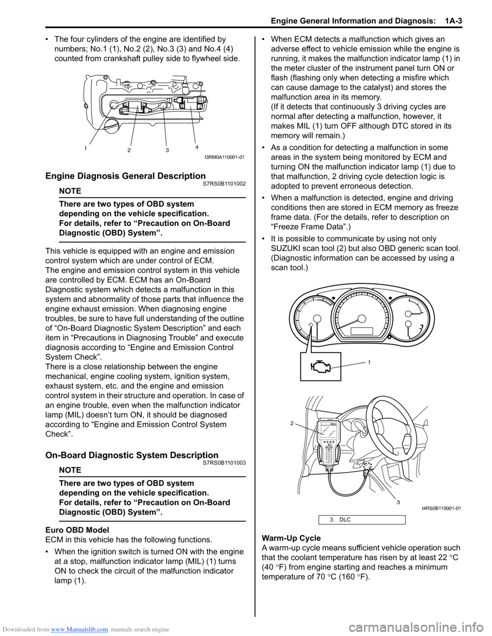
• The four cylinders of the engine are identified by numbers; No.1 (1), No.2 (2 ), No.3 (3) and No.4 (4)
counted from crankshaft pulley side to flywheel side.
Engine Diagnosis General DescriptionS7RS0B1101002
NOTE
There are two types of OBD system
depending on the vehicle specification.
For details, refer to “Precaution on On-Board
Diagnostic (OBD) System”.
This vehicle is equipped with an engine and emission
control system which are under control of ECM.
The engine and emission control system in this vehicle
are controlled by ECM. ECM has an On-Board
Diagnostic system which detects a malfunction in this
system and abnormality of those parts that influence the
engine exhaust emission. When diagnosing engine
troubles, be sure to have full understanding of the outline
of “On-Board Diagnostic System Description” and each
item in “Precautions in Diagnosing Trouble” and execute
diagnosis according to “Engine and Emission Control
System Check”.
There is a close relationship between the engine
mechanical, engine cooling system, ignition system,
exhaust system, etc. and the engine and emission
control system in their structure and operation. In case of
an engine trouble, even when the malfunction indicator
lamp (MIL) doesn’t turn ON, it should be diagnosed
according to “Engine and Emission Control System
Check”.
On-Board Diagnostic System DescriptionS7RS0B1101003
NOTE
There are two types of OBD system
depending on the vehicle specification.
For details, refer to “Precaution on On-Board
Diagnostic (OBD) System”.
Euro OBD Model
ECM in this vehicle has the following functions.
• When the ignition switch is turned ON with the engine at a stop, malfunction indicator lamp (MIL) (1) turns
ON to check the circuit of the malfunction indicator
lamp (1). • When ECM detects a malfunction which gives an
adverse effect to vehicle emission while the engine is
running, it makes the malfunction indicator lamp (1) in
the meter cluster of the inst rument panel turn ON or
flash (flashing only when detecting a misfire which
can cause damage to the catalyst) and stores the
malfunction area in its memory.
(If it detects that contin uously 3 driving cycles are
normal after detecting a malfunction, however, it
makes MIL (1) turn OFF although DTC stored in its
memory will remain.)
• As a condition for detecting a malfunction in some areas in the system being monitored by ECM and
turning ON the malfunction indicator lamp (1) due to
that malfunction, 2 driving cycle detection logic is
adopted to prevent erroneous detection.
• When a malfunction is detected, engine and driving conditions then are stored in ECM memory as freeze
frame data. (For the details, refer to description on
“Freeze Frame Data”.)
• It is possible to communicate by using not only SUZUKI scan tool (2) but also OBD generic scan tool.
(Diagnostic information can be accessed by using a
scan tool.)
Warm-Up Cycle
A warm-up cycle means sufficie nt vehicle operation such
that the coolant temperature has risen by at least 22 °C
(40 °F) from engine starting and reaches a minimum
temperature of 70 °C (160 ° F).
1
23 4
I3RM0A110001-01
3. DLC
2
3
1
I4RS0B110001-01
Page 58 of 1496
Downloaded from www.Manualslib.com manuals search engine 1A-8 Engine General Information and Diagnosis:
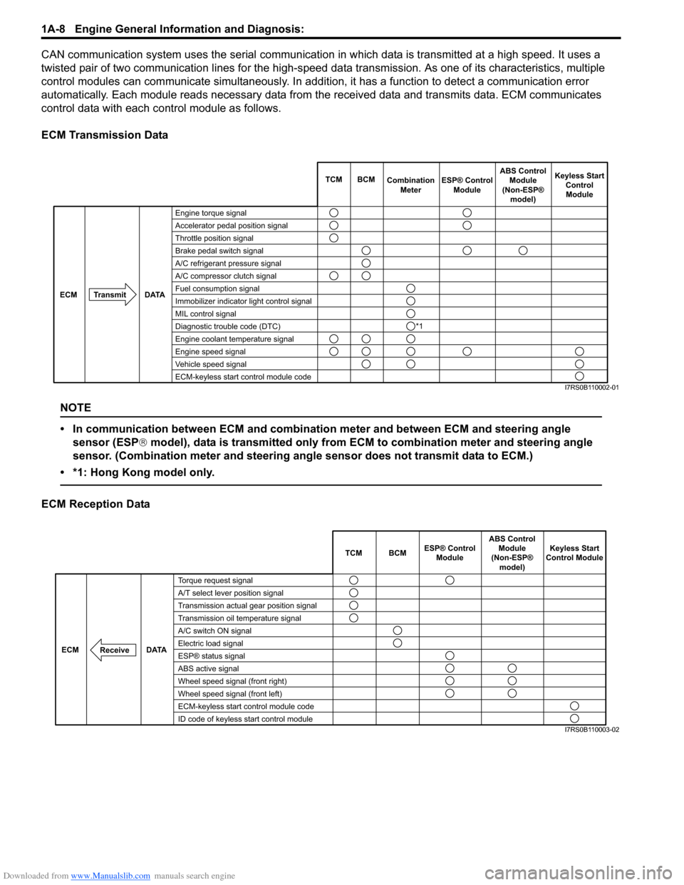
CAN communication system uses the serial communication in which data is transmitted at a high speed. It uses a
twisted pair of two communication lines for the high-speed da ta transmission. As one of its characteristics, multiple
control modules can communicate simultaneously. In addition, it has a function to detect a communication error
automatically. Each module reads necessary data from the received data and transmits data. ECM communicates
control data with each control module as follows.
ECM Transmission Data
NOTE
• In communication between ECM and combination meter and between ECM and steering angle sensor (ESP ® model), data is transmitted only from ECM to combination meter and steering angle
sensor. (Combination meter and steering angle sensor does not transmit data to ECM.)
• *1: Hong Kong model only.
ECM Reception Data
Engine torque signal
Accelerator pedal position signal
Throttle position signal
Brake pedal switch signal
A/C refrigerant pressure signal
A/C compressor clutch signal
Fuel consumption signal
Immobilizer indicator light control signal
MIL control signal
Diagnostic trouble code (DTC)
Engine coolant temperature signal
Engine speed signal
Vehicle speed signal
ECM-keyless start control module code TCM BCM
Combination
Meter Keyless Start
ControlModule
Transmit DATA
ECM
ESP® Control
Module ABS Control
Module
(Non-ESP® model)
*1
I7RS0B110002-01
TCM BCM Keyless Start
Control Module
DATA
ECM
Torque request signal
A/T select lever position signal
Transmission actual gear position signal
Transmission oil temperature signal
A/C switch ON signal
Electric load signal
ESP® status signal
ABS active signal
Wheel speed signal (front right)
Wheel speed signal (front left)
ECM-keyless start control module code
ID code of keyless start control module
Receive
ABS Control
Module
(Non-ESP® model)
ESP® Control
Module
I7RS0B110003-02
Page 77 of 1496
Downloaded from www.Manualslib.com manuals search engine Engine General Information and Diagnosis: 1A-27
DTC ClearanceS7RS0B1104004
NOTE
There are two types of OBD system
depending on the vehicle specification.
For details, refer to “Precaution on On-Board
Diagnostic (OBD) System”.
Using Scan Tool1) Connect OBD generic scan to ol or SUZUKI scan tool
to data link connector in the same manner as when
making this connection for DTC check.
2) Turn ignition switch OFF and then ON.
3) Erase DTC and pending DTC according to instructions displayed on scan tool. Refer to scan
tool operator’s manual for further details.
4) After completing the clear ance, turn ignition switch
OFF and disconnect scan tool from data link
connector.
NOTE
DTC and freeze frame data stored in ECM
memory are also cleared in the following
cases. Be careful not to clear them before
keeping their record.
• When power to ECM is cut off (by disconnecting battery cable, removing
fuse or disconnecting ECM connectors).
• When the same malfunction (DTC) is not detected again during 40 engine warm-up
cycles. (See “Warm-Up Cycle” of “On-
Board Diagnostic System Description”.)
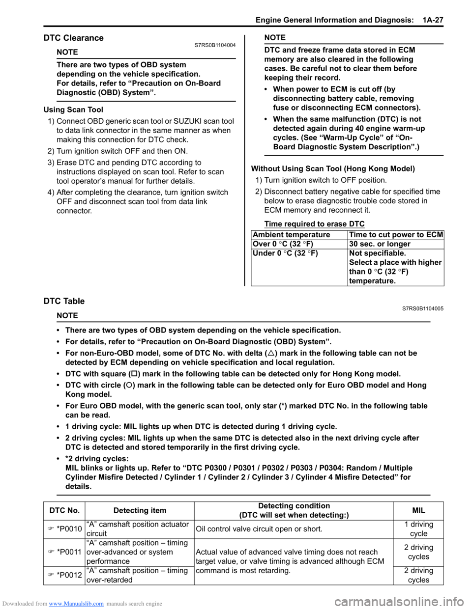
Without Using Scan Tool (Hong Kong Model)
1) Turn ignition switch to OFF position.
2) Disconnect battery negative cable for specified time below to erase diagnostic trouble code stored in
ECM memory and reconnect it.
Time required to erase DTC
DTC TableS7RS0B1104005
NOTE
• There are two types of OBD system depending on the vehicle specification.
• For details, refer to “Precaution on On-Board Diagnostic (OBD) System”.
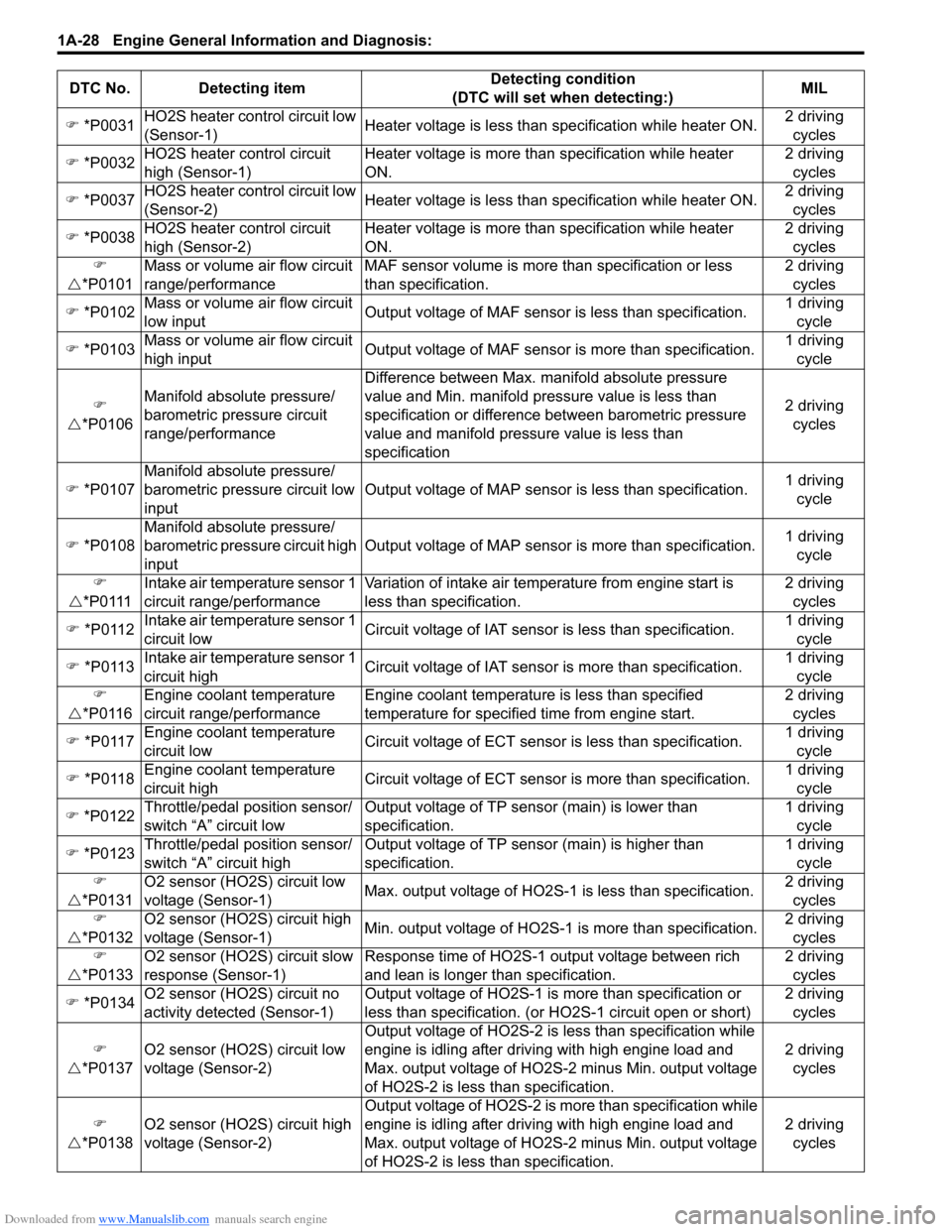
• For non-Euro-OBD model, some of DTC No. with delta ( �U) mark in the following table can not be
detected by ECM depending on vehicl e specification and local regulation.
• DTC with square ( �†) mark in the following table can be detected only for Hong Kong model.
• DTC with circle ( �{) mark in the following table can be detected only for Euro OBD model and Hong
Kong model.
• For Euro OBD model, with the generic scan tool, onl y star (*) marked DTC No. in the following table
can be read.
• 1 driving cycle: MIL lights up when DTC is detected during 1 driving cycle.
• 2 driving cycles: MIL lights up when the same DTC is detected also in the next driving cycle after DTC is detected and stored temporarily in the first driving cycle.
• *2 driving cycles: MIL blinks or lights up. Refer to “DTC P0300 / P0301 / P0302 / P0303 / P0304: Random / Multiple
Cylinder Misfire Detected / Cylinder 1 / Cylinder 2 / Cylinder 3 / Cylinder 4 Misfire Detected” for
details.
Ambient temperature Time to cut power to ECM
Over 0 °C (32 ° F) 30 sec. or longer
Under 0 °C (32 °F) Not specifiable.
Select a place with higher
than 0 °C (32 °F)
temperature.
DTC No. Detecting item Detecting condition
(DTC will set when detecting:) MIL
�) *P0010 “A” camshaft position actuator
circuit Oil control valve circuit open or short. 1 driving
cycle
�) *P0011 “A” camshaft position – timing
over-advanced or system
performance Actual value of advanced va
lve timing does not reach
target value, or valve timi ng is advanced although ECM
command is most retarding. 2 driving
cycles
�) *P0012 “A” camshaft position – timing
over-retarded 2 driving
cycles
Page 78 of 1496
Downloaded from www.Manualslib.com manuals search engine 1A-28 Engine General Information and Diagnosis:
�) *P0031 HO2S heater control circuit low
(Sensor-1) Heater voltage is less than specification while heater ON. 2 driving
cycles
�) *P0032 HO2S heater control circuit
high (Sensor-1) Heater voltage is more than
specification while heater
ON. 2 driving
cycles
�) *P0037 HO2S heater control circuit low
(Sensor-2) Heater voltage is less than specification while heater ON. 2 driving
cycles
�) *P0038 HO2S heater control circuit
high (Sensor-2) Heater voltage is more than
specification while heater
ON. 2 driving
cycles
�)
�U *P0101 Mass or volume air flow circuit
range/performance MAF sensor volume is more
than specification or less
than specification. 2 driving
cycles
�) *P0102 Mass or volume air flow circuit
low input Output voltage of MAF sensor is less than specification. 1 driving
cycle
�) *P0103 Mass or volume air flow circuit
high input Output voltage of MAF sensor is more than specification. 1 driving
cycle
�)
�U *P0106 Manifold absolute pressure/
barometric pressure circuit
range/performance Difference between Max. manifold absolute pressure
value and Min. manifold pressure value is less than
specification or difference between barometric pressure
value and manifold pressure value is less than
specification
2 driving
cycles
�) *P0107 Manifold absolute pressure/
barometric pressure circuit low
input Output voltage of MAP sensor
is less than specification.1 driving
cycle
�) *P0108 Manifold absolute pressure/
barometric pressure circuit high
input Output voltage of MAP sensor is more than specification.
1 driving
cycle
�)
�U *P0111 Intake air temperature sensor 1
circuit range/performance Variation of intake air temperature from engine start is
less than specification. 2 driving
cycles
�) *P0112 Intake air temperature sensor 1
circuit low Circuit voltage of IAT sensor is less than specification. 1 driving
cycle
�) *P0113 Intake air temperature sensor 1
circuit hig
h Circuit voltage of IAT sensor
is more than specification. 1 driving
cycle
�)
�U *P0116 Engine coolant temperature
circuit range/performance Engine coolant temperature is less than specified
temperature for specified time from engine start. 2 driving
cycles
�) *P0117 Engine coolant temperature
circuit low Circuit voltage of ECT sensor
is less than specification. 1 driving
cycle
�) *P0118 Engine coolant temperature
circuit high Circuit voltage of ECT sensor
is more than specification. 1 driving
cycle
�) *P0122 Throttle/pedal position sensor/
switch “A” circuit low Output voltage of TP sensor (main) is lower than
specification. 1 driving
cycle
�) *P0123 Throttle/pedal position sensor/
switch “A” circuit high Output voltage of TP sensor (main) is higher than
specification. 1 driving
cycle
�)
�U *P0131 O2 sensor (HO2S) circuit low
voltage (Sensor-1)
Max. output voltage of HO2S-1
is less than specification.2 driving
cycles
�)
�U *P0132 O2 sensor (HO2S) circuit high
voltage (Sensor-1)
Min. output voltage of HO2S-1
is more than specification. 2 driving
cycles
�)
�U *P0133 O2 sensor (HO2S) circuit slow
response (Sensor-1) Response time of HO2S-1 output voltage between rich
and lean is longer than specification. 2 driving
cycles
�) *P0134 O2 sensor (HO2S) circuit no
activity detected (Sensor-1) Output voltage of HO2S-1 is
more than specification or
less than specification. (or HO2S-1 circuit open or short) 2 driving
cycles
�)
�U *P0137 O2 sensor (HO2S) circuit low
voltage (Sensor-2) Output voltage of HO2S-2 is
less than specification while
engine is idling after driving with high engine load and
Max. output voltage of HO2S-2 minus Min. output voltage
of HO2S-2 is less than specification. 2 driving
cycles
�)
�U *P013
8 O2 sensor (HO2S) circuit high
voltage (Sensor-2) Output voltage of HO2S-2 is
more than specification while
engine is idling after driving with high engine load and
Max. output voltage of HO2S-2 minus Min. output voltage
of HO2S-2 is less than specification. 2 driving
cycles
DTC No. Detecting item
Detecting condition
(DTC will set when detecting:) MIL
Page 81 of 1496
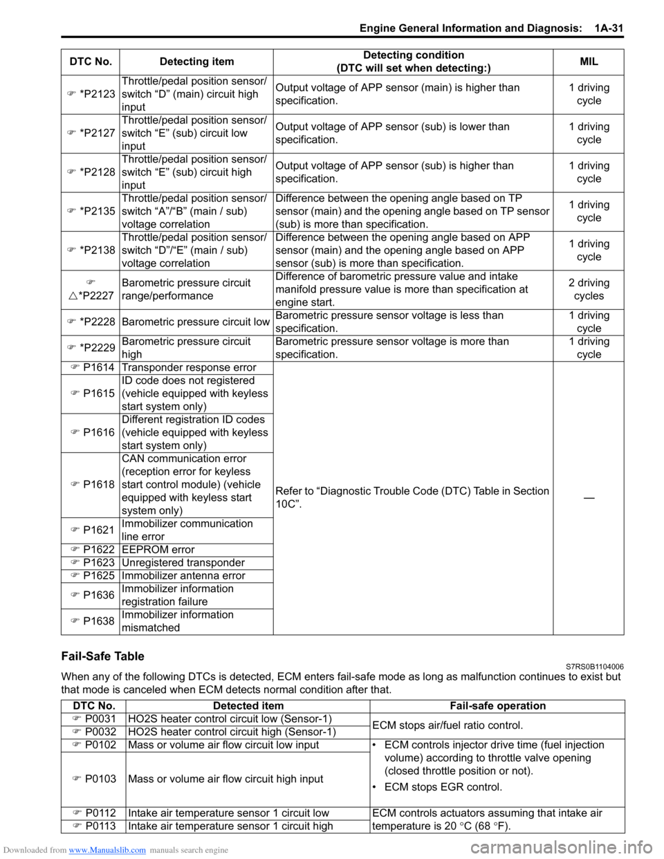
Downloaded from www.Manualslib.com manuals search engine Engine General Information and Diagnosis: 1A-31
Fail-Safe TableS7RS0B1104006
When any of the following DTCs is detected, ECM enters fail-safe mode as long as malfunction continues to exist but
that mode is canceled when ECM de tects normal condition after that.
�)
*P2123 Throttle/pedal position sensor/
switch “D” (main) circuit high
input Output voltage of APP sensor (main) is higher than
specification.
1 driving
cycle
�) *P2127 Throttle/pedal position sensor/
switch “E” (sub) circuit low
input Output voltage of APP sens
or (sub) is lower than
specification. 1 driving
cycle
�) *P2128 Throttle/pedal position sensor/
switch “E” (sub) circuit high
input Output voltage of APP sensor (sub) is higher than
specification.
1 driving
cycle
�) *P2135 Throttle/pedal position sensor/
switch “A”/“B” (main / sub)
voltage correlation Difference between the opening angle based on TP
sensor (main) and the opening angle based on TP sensor
(sub) is more than specification.
1 driving
cycle
�) *P2138 Throttle/pedal position sensor/
switch “D”/“E” (main / sub)
voltage correlation Difference between the opening angle based on APP
sensor (main) and the opening angle based on APP
sensor (sub) is more
than specification. 1 driving
cycle
�)
�U *P2227 Barometric pressure circuit
range/performance Difference of barometric pressure value and intake
manifold pressure value is
more than specification at
engine start. 2 driving
cycles
�) *P2228 Barometric pressure circuit low Barometric pressure sens
or voltage is less than
specification. 1 driving
cycle
�) *P2229 Barometric pressure circuit
high Barometric pressure sensor voltage is more than
specification. 1 driving
cycle
�) P1614 Transponder response error
Refer to “Diagnostic Trouble Code (DTC) Table in Section
10C”. —
�) P1615 ID code does not registered
(vehicle equipped with keyless
start system only)
�) P1616 Different registration ID codes
(vehicle equipped with keyless
start system only)
�) P1618 CAN communication error
(reception error for keyless
start control module) (vehicle
equipped with keyless start
system only)
�) P1621 Immobilizer communication
line error
�) P1622
EEPROM error
�) P1623 Unregistered transponder
�) P1625 Immobilizer antenna error
�) P1636 Immobilizer information
registration failure
�) P1638 Immobilizer information
mismatched
DTC No. Detecting item
Detecting condition
(DTC will set when detecting:) MIL
DTC No.
Detected item Fail-safe operation
�) P0031 HO2S heater control circuit low (Sensor-1)
ECM stops air/fuel ratio control.
�) P0032 HO2S heater control circuit high (Sensor-1)
�) P0102 Mass or volume air flow circuit low input • ECM controls injector drive time (fuel injection
volume) according to throttle valve opening
(closed throttle position or not).
• ECM stops EGR control.
�)
P0103 Mass or volume air flow circuit high input
�) P0112 Intake air temperature sensor 1 circuit low ECM controls actuators assuming that intake air
temperature is 20 °C (68 ° F).
�) P0113 Intake air temperature sensor 1 circuit high
Page 82 of 1496
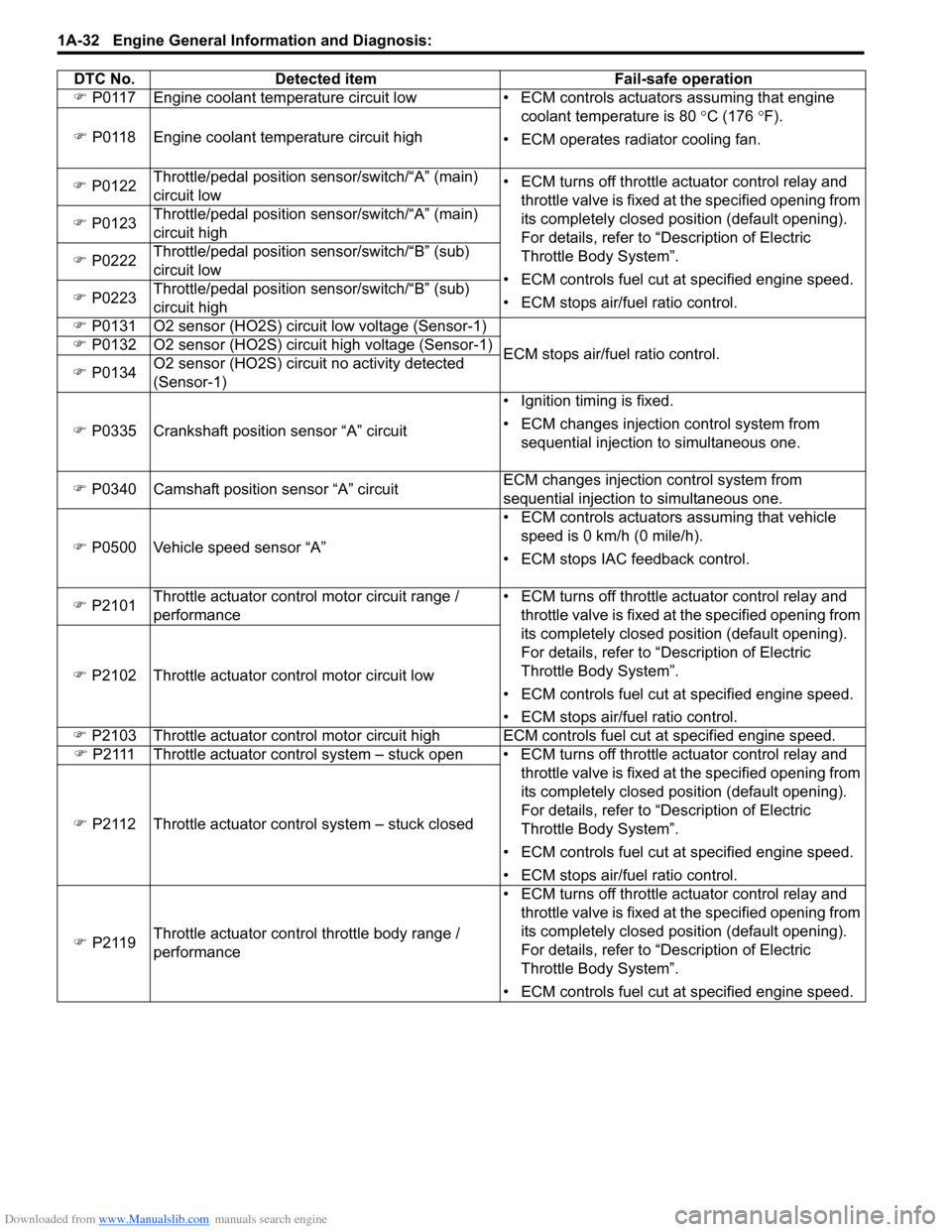
Downloaded from www.Manualslib.com manuals search engine 1A-32 Engine General Information and Diagnosis:
�) P0117 Engine coolant temperature circuit low • EC M controls actuators assuming that engine
coolant temperature is 80 °C (176 °F).
• ECM operates radiator cooling fan.
�)
P0118 Engine coolant temperature circuit high
�) P0122 Throttle/pedal position sensor/switch/“A” (main)
circuit low • ECM turns off throttle actuator control relay and
throttle valve is fixed at the specified opening from
its completely closed position (default opening).
For details, refer to “Description of Electric
Throttle Body System”.
• ECM controls fuel cut at specified engine speed.
• ECM stops air/fuel ratio control.
�)
P0123 Throttle/pedal position sensor/switch/“A” (main)
circuit high
�) P0222 Throttle/pedal position sensor/switch/“B” (sub)
circuit low
�) P0223 Throttle/pedal position sensor/switch/“B” (sub)
circuit high
�) P0131 O2 sensor (HO2S) circuit low voltage (Sensor-1)
ECM stops air/fuel ratio control.
�)
P0132 O2 sensor (HO2S) circuit high voltage (Sensor-1)
�) P0134 O2 sensor (HO2S) circuit no activity detected
(Sensor-1)
�) P0335 Crankshaft position sensor “A” circuit • Ignition timing is fixed.
• ECM changes injection control system from
sequential injection to simultaneous one.
�) P0340 Camshaft position sensor “A” circuit ECM changes injection
control system from
sequential injection to simultaneous one.
�) P0500 Vehicle speed sensor “A” • ECM controls actuators assuming that vehicle
speed is 0 km/h (0 mile/h).
• ECM stops IAC feedback control.
�) P2101 Throttle actuator control motor circuit range /
performance • ECM turns off throttle actuator control relay and
throttle valve is fixed at the specified opening from
its completely closed position (default opening).
For details, refer to “Description of Electric
Throttle Body System”.
• ECM controls fuel cut at specified engine speed.
• ECM stops air/fuel ratio control.
�)
P2102 Throttle actuator control motor circuit low
�) P2103 Throttle actuator control motor circuit high ECM controls fuel cut at specified engine speed.
�) P2111 Throttle actuator control system – stuck open • EC M turns off throttle actuator control relay and
throttle valve is fixed at the specified opening from
its completely closed position (default opening).
For details, refer to “Description of Electric
Throttle Body System”.
• ECM controls fuel cut at specified engine speed.
• ECM stops air/fuel ratio control.
�)
P2112 Throttle actuator control system – stuck closed
�) P2119 Throttle actuator control throttle body range /
performance • ECM turns off throttle actuator control relay and
throttle valve is fixed at the specified opening from
its completely closed position (default opening).
For details, refer to “Description of Electric
Throttle Body System”.
• ECM controls fuel cut at specified engine speed.
DTC No.
Detected item Fail-safe operation
Page 84 of 1496
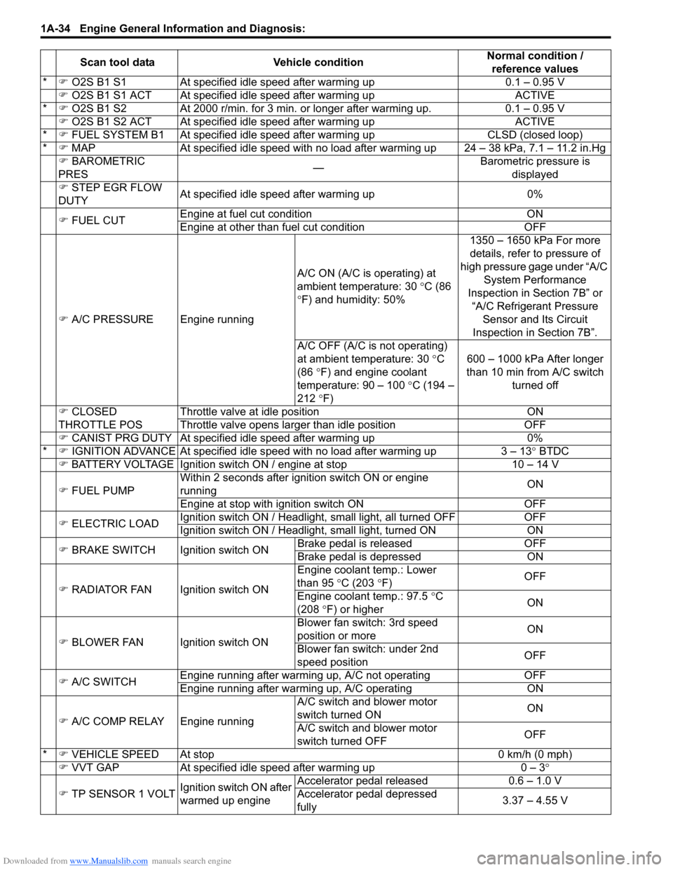
Downloaded from www.Manualslib.com manuals search engine 1A-34 Engine General Information and Diagnosis:
*�) O2S B1 S1 At specified idle speed after warming up 0.1 – 0.95 V
�) O2S B1 S1 ACT At specified id le speed after warming up ACTIVE
* �) O2S B1 S2 At 2000 r/min. for 3 min. or longer after warming up. 0.1 – 0.95 V
�) O2S B1 S2 ACT At specified id le speed after warming up ACTIVE
* �) FUEL SYSTEM B1 At specif ied idle speed after warming up CLSD (closed loop)
* �) MAP At specified idle speed with no load after warming up 24 – 38 kPa, 7.1 – 11.2 in.Hg
�) BAROMETRIC
PRES —Barometric pressure is
displayed
�) STEP EGR FLOW
DUTY At specified idle speed after warming up 0%
�) FUEL CUT Engine at fuel cut condition ON
Engine at other than fuel cut condition OFF
�) A/C PRESSURE Engine running A/C ON (A/C is operating) at
ambient temperature: 30
°C (86
° F) and humidity: 50% 1350 – 1650 kPa For more
details, refer to pressure of
high pressure gage under “A/C System Performance
Inspection in Section 7B” or “A/C Refrigerant Pressure Sensor and Its Circuit
Inspection in Section 7B”.
A/C OFF (A/C is not operating)
at ambient temperature: 30 ° C
(86 °F) and engine coolant
temperature: 90 – 100 °C (194 –
212 °F) 600 – 1000 kPa After longer
than 10 min from A/C switch turned off
�) CLOSED
THROTTLE POS Throttle valve at idle position ON
Throttle valve opens larger than idle position OFF
�) CANIST PRG DUTY At specified idle speed after warming up 0%
* �) IGNITION ADVANCE At specified idle s peed with no load after warming up 3 – 13 ° BTDC
�) BATTERY VOLTAGE Ignition switch ON / engine at stop 10 – 14 V
�) FUEL PUMP Within 2 seconds after ignition switch ON or engine
running
ON
Engine at stop with ignition switch ON OFF
�) ELECTRIC LOAD Ignition switch ON / Headligh
t, small light, all turned OFF OFF
Ignition switch ON / Headli ght, small light, turned ON ON
�) BRAKE SWITCH Igni tion switch ONBrake pedal is released OFF
Brake pedal is depressed ON
�) RADIATOR FAN Ignition switch ON Engin
e coolant temp.: Lower
than 95 °C (203 °F) OFF
Engine coolant temp.: 97.5 °C
(208 °F) or higher ON
�) BLOWER FAN Ignition switch ON Blower fan switch: 3rd speed
position or more
ON
Blower fan switch: under 2nd
speed position OFF
�) A/C SWITCH Engine running after warming up, A/C not operating
OFF
Engine running after warming up, A/C operating ON
�) A/C COMP RELAY Engine running A/C switch and blower motor
switch turned ON
ON
A/C switch and blower motor
switch turned OFF OFF
* �) VEHICLE SPEED At stop 0 km/h (0 mph)
�) VVT GAP At specified idle speed after warming up 0 – 3°
�) TP SENSOR 1 VOLT Ignition switch ON after
warmed up engine Accelerator pedal released
0.6 – 1.0 V
Accelerator pedal depressed
fully 3.37 – 4.55 V
Scan tool data
Vehicle condition Normal condition /
reference values
Page 85 of 1496
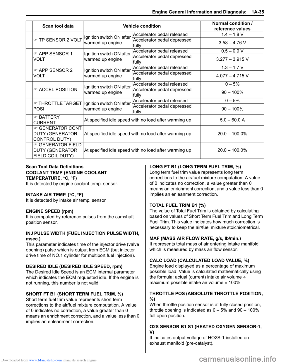
Downloaded from www.Manualslib.com manuals search engine Engine General Information and Diagnosis: 1A-35
Scan Tool Data Definitions
COOLANT TEMP (ENGINE COOLANT
TEMPERATURE, °C, °F)
It is detected by engine coolant temp. sensor.
INTAKE AIR TEMP. ( °C, °F)
It is detected by intake air temp. sensor.
ENGINE SPEED (rpm)
It is computed by reference pulses from the camshaft
position sensor.
INJ PULSE WIDTH (FUEL INJECTION PULSE WIDTH,
msec.)
This parameter indicates time of the injector drive (valve
opening) pulse which is output from ECM (but injector
drive time of NO.1 cylinder fo r multiport fuel injection).
DESIRED IDLE (DESIRED IDLE SPEED, rpm)
The Desired Idle Speed is an ECM internal parameter
which indicates the ECM requested idle. If the engine is
not running, this number is not valid.
SHORT FT B1 (SHORT TERM FUEL TRIM, %)
Short term fuel trim valu e represents short term
corrections to the air/fuel mixture computation. A value
of 0 indicates no correction, a value greater than 0
means an enrichment correction, and a value less than 0
implies an enleanment correction. LONG FT B1 (LONG TERM FUEL TRIM, %)
Long term fuel trim value represents long term
corrections to the air/fuel mixture computation. A value
of 0 indicates no correction, a value greater than 0
means an enrichment correction, and a value less than 0
implies an enleanment correction.
TOTAL FUEL TRIM B1 (%)
The value of Total Fuel Trim is obtained by calculating
based on values of Short Term Fuel Trim and Long Term
Fuel Trim. This value indica
tes how much correction is
necessary to keep the air/fuel mixture stoichiometrical.
MAF (MASS AIR FLOW RATE, g/s, lb/min.)
It represents total mass of air entering intake manifold
which is measured by mass air flow sensor.
CALC LOAD (CALCULATED LOAD VALUE, %)
Engine load displayed as a percentage of maximum
possible load. Value is calculated mathematically using
the formula: actual (current) intake air volume ÷
maximum possible intake air volume × 100%
THROTTLE POS (ABSOLUTE THROTTLE POSITION,
%)
When throttle position sensor is at fully closed position,
throttle opening is indicated as 0 – 5% and 90 – 100%
full open position.
O2S SENSOR B1 S1 (HEA TED OXYGEN SENSOR-1,
V)
It indicates output voltage of HO2S-1 installed on
exhaust manifold (pre-catalyst).
�)
TP SENSOR 2 VOLT Ignition switch ON after
warmed up engine Accelerator pedal released
1.4 – 1.8 V
Accelerator pedal depressed
fully 3.58 – 4.76 V
�) APP SENSOR 1
VOLT Ignition switch ON after
warmed up engineAccelerator pedal released
0.5 – 0.9 V
Accelerator pedal depressed
fully 3.277 – 3.915 V
�) APP SENSOR 2
VOLT Ignition switch ON after
warmed up engineAccelerator pedal released
1.3 – 1.7 V
Accelerator pedal depressed
fully 4.077 – 4.715 V
�) ACCEL POSITION Ignition switch ON after
warmed up engine Accelerator pedal released
0 – 5%
Accelerator pedal depressed
fully 90 – 100%
�) THROTTLE TARGET
POSI Ignition switch ON after
warmed up engineAccelerator pedal released
0 – 5%
Accelerator pedal depressed
fully 90 – 100%
�) BATTERY
CURRENT At specified idle speed with no load after warming up
5.0 – 60.0 A
�) GENERATOR CONT
DUTY (GENERATOR
CONTROL DUTY) At specified idle speed with no load after warming up
20.0 – 100.0%
�) GENERATOR FIELD
DUTY (GENERATOR
FIELD COIL DUTY) At spe
cified idle speed with no load after warming up
20.0 – 100.0%
Scan tool data
Vehicle condition Normal condition /
reference values