2006 SUZUKI SWIFT Led panel
[x] Cancel search: Led panelPage 1159 of 1496

Downloaded from www.Manualslib.com manuals search engine Air Bag System: 8B-121
Deployment / Activation Inside of Vehicle
When the vehicle will be destroyed, or salvaged for
component parts, deploy the air bag modules and/or
activate seat belt pretensioners installed on vehicle.
NOTE
If equipped with the seat belt pretensioners,
activate both side of seat belt pretensioners
at the same time when using special tool (C).
1) Turn ignition switch to LOCK position, remove key
and put on safety glasses.
2) Remove all loose objects from front seats and instrument panel.
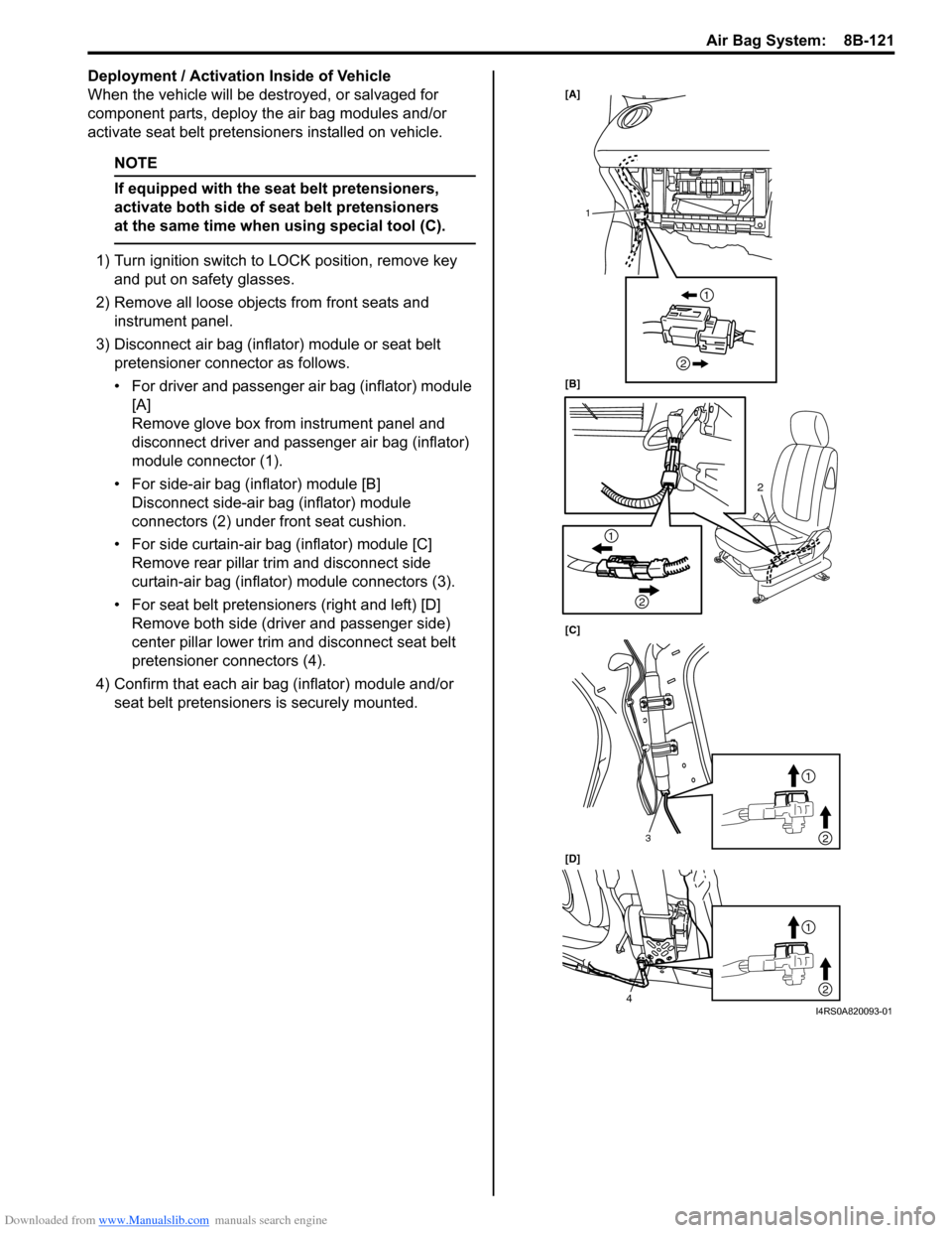
3) Disconnect air bag (inflator) module or seat belt pretensioner connector as follows.
• For driver and passenger air bag (inflator) module [A]
Remove glove box from instrument panel and
disconnect driver and passenger air bag (inflator)
module connector (1).
• For side-air bag (inflator) module [B] Disconnect side-air bag (inflator) module
connectors (2) under front seat cushion.
• For side curtain-air bag (inflator) module [C] Remove rear pillar trim and disconnect side
curtain-air bag (inflator) module connectors (3).
• For seat belt pretensioners (right and left) [D] Remove both side (driver and passenger side)
center pillar lower trim an d disconnect seat belt
pretensioner connectors (4).
4) Confirm that each air bag (inflator) module and/or seat belt pretensioners is securely mounted.
[A]
[B]
[C]
[D]
2
1
3
4
1
2
1
2
1
2
1
2
I4RS0A820093-01
Page 1164 of 1496

Downloaded from www.Manualslib.com manuals search engine 8B-126 Air Bag System:
The adapter (1) will also give an idea of whether or not
contact tension is sufficient, helping to find an open or
intermittent open due to poor terminal contact. An SDM
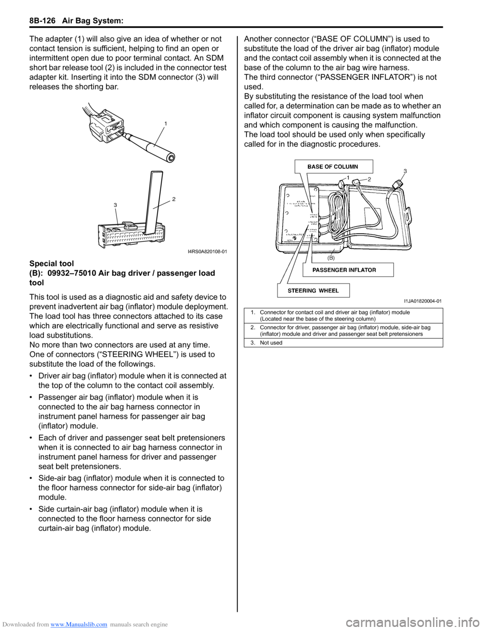
short bar release tool (2) is included in the connector test
adapter kit. Inserting it in to the SDM connector (3) will
releases the shorting bar.
Special tool
(B): 09932–75010 Air bag driver / passenger load
tool
This tool is used as a diagno stic aid and safety device to
prevent inadvertent air bag (inflator) module deployment.
The load tool has three connectors attached to its case
which are electrically functional and serve as resistive
load substitutions.
No more than two connectors are used at any time.
One of connectors (“STEER ING WHEEL”) is used to
substitute the load of the followings.
• Driver air bag (inflator) module when it is connected at the top of the column to the contact coil assembly.
• Passenger air bag (inflator) module when it is connected to the air bag harness connector in
instrument panel harness for passenger air bag
(inflator) module.
• Each of driver and passen ger seat belt pretensioners
when it is connected to air bag harness connector in
instrument panel harness for driver and passenger
seat belt pretensioners.
• Side-air bag (inflator) module when it is connected to the floor harness connector for side-air bag (inflator)
module.
• Side curtain-air bag (inflator) module when it is connected to the floor harness connector for side
curtain-air bag (inflator) module. Another connec
tor (“BASE OF COLUMN ”) is used to
substitute the load of the driver air bag (inflator) module
and the contact coil assembly when it is connected at the
base of the column to the air bag wire harness.
The third connector (“PASSENGER INFLATOR”) is not
used.
By substituting the resistan ce of the load tool when
called for, a determination can be made as to whether an
inflator circuit component is causing system malfunction
and which component is causing the malfunction.
The load tool should be used only when specifically
called for in the diagnostic procedures.
1
2
3
I4RS0A820108-01
1. Connector for contact coil and driver air bag (inflator) module
(Located near the base of the steering column)
2. Connector for driver, passenger air bag (inflator) module, side-air bag (inflator) module and driver and passenger seat belt pretensioners
3. Not used
I1JA01820004-01
Page 1371 of 1496

Downloaded from www.Manualslib.com manuals search engine Hood / Fenders / Doors: 9J-2
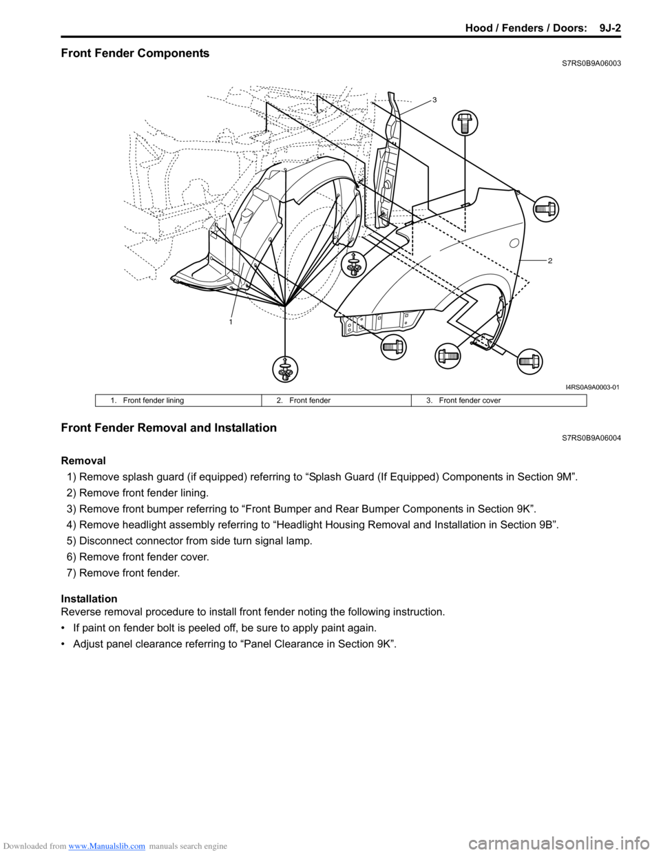
Front Fender ComponentsS7RS0B9A06003
Front Fender Removal and InstallationS7RS0B9A06004
Removal1) Remove splash guard (if equipped) referring to “Splash Guard (If Equipped) Components in Section 9M”.
2) Remove front fender lining.
3) Remove front bumper referring to “Front Bumper and Rear Bumper Components in Section 9K”.
4) Remove headlight assembly referring to “Headlig ht Housing Removal and Installation in Section 9B”.
5) Disconnect connector from side turn signal lamp.
6) Remove front fender cover.
7) Remove front fender.
Installation
Reverse removal procedure to install fron t fender noting the following instruction.
• If paint on fender bolt is peeled off, be sure to apply paint again.
• Adjust panel clearance referring to “Panel Clearance in Section 9K”.
1 2
3
I4RS0A9A0003-01
1. Front fender lining
2. Front fender3. Front fender cover
Page 1388 of 1496

Downloaded from www.Manualslib.com manuals search engine 9L-1 Paint / Coatings:
Body, Cab and Accessories
Paint / Coatings
General Description
Anti-Corrosion Treatment ConstructionS7RS0B9C01001
WARNING!
Standard shop practices, particularly eye protection, should be followed during the performance of the
following operations to avoid personal injury.
As rust proof treatment, steel sheets are given corrosion resistance on the interior and/or exterior.
These corrosion resistance steel sheet materials ar e called one of two-side galvanized steel sheets.
It is for the sake of rust protection that these materials are selected and given a variety of treatments as described
blow.
• Steel sheets are treated with cathodic electro primer which is excellent in corrosion resistance.
• Rust proof wax coatings are applied to door and side sill insides where mois ture is liable to stay.
• Vinyl coating is applied to body underside and wheel housing inside.
• Sealer is applied to door hem, engine compartment steel sheet-to-steel sheet joint, and the like portions to prevent water penetration and resulting in rust occurrence.
In panel replacement or collision damage repair, leaving the relevant area untreated as it is in any operation which
does disturb the rust proof treatment will cause corrosion to th at area. Therefore, it is the essential function of any
repair operation to correctly recoat t he related surfaces of the relevant area.
All the metal panels are coated with metal conditioners an d primer coating during vehicle production. Following the
repair and/or replacement parts installation, every access ible bare metal surface should be cleaned and coated with
rust proof primer. Perform this operation prior to the application of sealer and rust proof wax coating.
Sealer is applied to the spec ific joints of a vehicle during production. The sealer is intended to prevent dust from
entering the vehicle and serves also as an anti corrosion barrier. The sealer is applied to the door and hood hem areas
and between panels. Correct and reseal the originally sealed joints if damaged. Reseal the attaching joints of a new
replacement panel and reseal the hem area of a replacement door or hood.
Use a quality sealer to seal the flanged joints, overlap joints and seams. The sealer must have flexible characteristics
and paint ability after it’s applied to repair areas.
For the sealer to fill open joints, use caulking material. Select a sealer in conf ormance with the place and purpose of a
specific use. Observe the ma nufacturer’s label-stand instructions when using the sealer.
In many cases, repaired places require color painting. When this is required, follow the ordinary techniques specified
for the finish preparation, color painting and undercoating build-up.
Rust proof wax, a penetrative compound, is applied to the metal-to-metal surfaces (door and side sill insides) where it
is difficult to use ordinary undercoating material for coating. Therefore, when selecting the rust proof wax, it may be the
penetrative type.
During the undercoating (vinyl coating) application, care should be taken that sealer is not applied to the engine-
related parts and shock absorber mounting or rotating parts. Following the under coating, make sure that body drain
holes are kept open.
The sequence of the application steps of the anti-corrosion materials are as follows:
1) Clean and prepare the metal surface.
2) Apply primer.
3) Apply sealer (all joints sealed originally).
4) Apply color in areas where color is required such as hem flanges, exposed joints and under body components.
5) Apply anti corrosion compound (penetrative wax).
6) Apply undercoating (rust proof material).