Page 954 of 1496

Downloaded from www.Manualslib.com manuals search engine 7B-6 Air Conditioning System: Manual Type
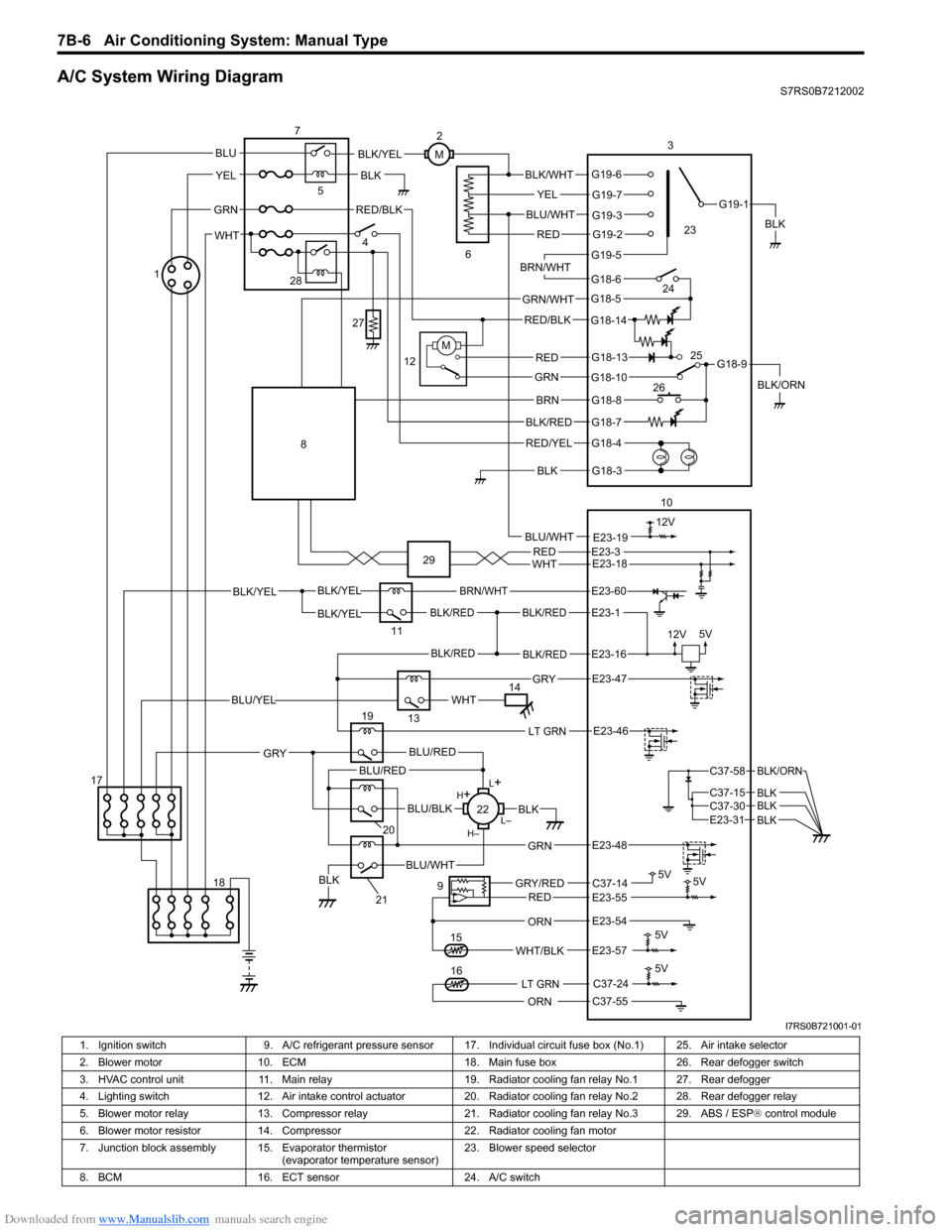
A/C System Wiring DiagramS7RS0B7212002
BLK/REDBLK/RED
BLK/YELBLK/YEL
BLK/YEL
BRN/WHT
12V5V
5V 5V
5V11
E23-1
E23-60
BLK/REDBLK/REDE23-16
E23-57WHT/BLK
9
13
E23-55C37-14GRY/REDRED
BLK
ORN
E23-47 GRY
WHTBLU/YEL
RED/BLK
14 3
1
15
5
7
BLK
2
M
12VBLU/WHTE23-19
C37-24
C37-55ORN
5V
LT GRN16
G18-3
G18-4
G18-7
G18-8
G18-10
G18-13
G18-5
G18-6
G19-5
G19-2
G19-3
G19-7
G19-6
G19-1
G18-9
G18-14
BLK/WHT
YEL
BLU/WHT
RED
BRN/WHT
GRN/WHT
RED/BLK
RED
GRN
BRN
BLK/RED
RED/YEL
BLK
BLK/YEL
BLK/ORN
4
6
12
10
M
E23-54
REDWHTE23-3E23-18
17 18
LT GRNE23-46
L+
L–
H–
H
+
BLU/RED
BLK
BLU/WHTBLK
BLU/BLK
20
GRN
GRY
E23-48
19
21
22
BLU/REDC37-58
C37-15 C37-30
BLK/ORN
BLKBLKE23-31 BLK
BLU
YEL
GRN
WHT
23
24
26 25
28
27
8
29
I7RS0B721001-01
1. Ignition switch
9. A/C refrigerant pressure sensor 17. I ndividual circuit fuse box (No.1) 25. Air intake selector
2. Blower motor 10. ECM 18. Main fuse box 26. Rear defogger switch
3. HVAC control unit 11. Main relay 19. Radiator cooling fan relay No.1 27. Rear defogger
4. Lighting switch 12. Air intake control actuator 20. Radiator cooling fan relay No.2 28. Rear defogger relay
5. Blower motor relay 13. Compressor relay 21. Radiator cooling fan relay No.3 29. ABS / ESP ® control module
6. Blower motor resistor 14. Compressor 22. Radiator cooling fan motor
7. Junction block assembly 15. Evaporator thermistor (evaporator temperature sensor)23. Blower speed selector
8. BCM 16. ECT sensor 24. A/C switch
Page 986 of 1496

Downloaded from www.Manualslib.com manuals search engine 7B-38 Air Conditioning System: Automatic Type
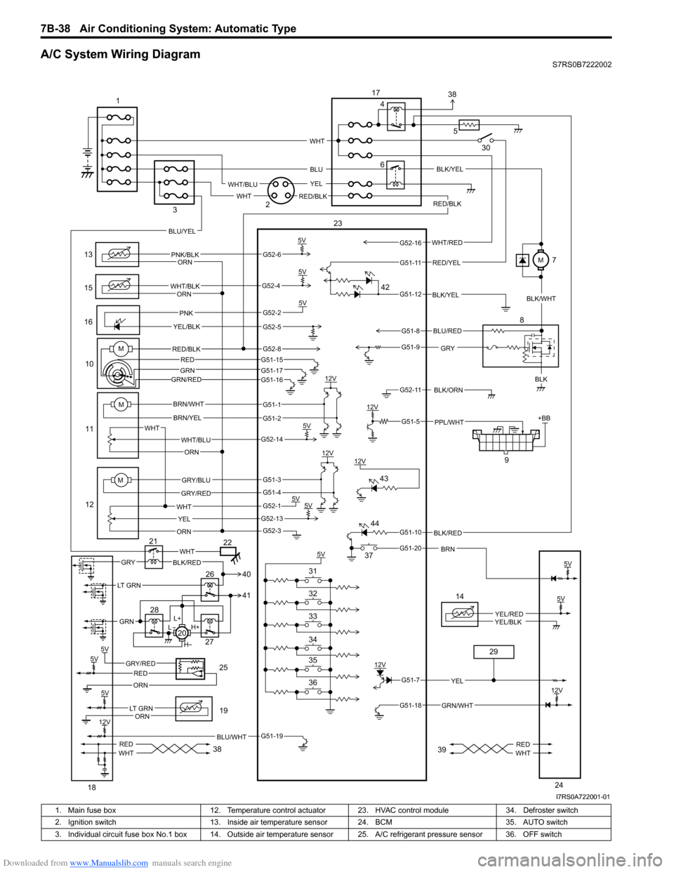
A/C System Wiring DiagramS7RS0B7222002
6
13
15
1610
11
12 9
12V
5V
5V5V
12V
12V
5V 5V
5V +BB
PNK/BLK
WHT/BLK
GRYBLK
WHT/BLU
WHT YEL
ORN
BRN/WHT
BRN/YEL
GRY/BLU
GRY/RED
PNK
YEL/BLK
BLK/ORN
PPL/WHT
12V BLK/YEL
WHT
ORN
ORN
ORN
5V
BLK/RED
BRN
RED/BLK
5V
5VGRY/REDRED
ORN
BLU/WHT
14
YEL/REDYEL/BLK
GRN/WHT
12V
YEL
L+
H+
L
H
WHTGRYBLK/RED
REDWHTREDWHT
M
M
WHT/RED
5
BLU
YEL
WHT
WHT/BLU
RED/BLKWHT
RED/YEL
BLU/YEL
LT GRN
GRN
BLU/RED
G52-6
G52-4
G52-2
G52-5
G51-1
G51-2
G52-14
G51-3
G51-4
G52-1
G52-13
G52-3
G51-19
G51-7
G51-18
G51-10
G51-20
G51-5
G52-11
G51-9
G51-8
G51-12
G51-11
G52-16
5V
12V
5V
12V
LT GRNORN
5V
23
1
2
3 4
8
17
18 19
20
21
22
24
25
26
27
28
29
30
36 35 34 33 32 31 37
38 3938
41 40
42
43
44
MRED/BLK
GRN/RED
G52-8G51-15
G51-17G51-16
REDGRN
BLK/YEL
BLK/WHT
M7
I7RS0A722001-01
1. Main fuse box 12. Temperature control actuator 23. HVAC control module 34. Defroster switch
2. Ignition switch 13. Inside air temperature sensor 24. BCM 35. AUTO switch
3. Individual circuit fuse box No.1 box 14. Outside air temper ature sensor 25. A/C refrigerant pressure sensor 36. OFF switch
Page 1064 of 1496
Downloaded from www.Manualslib.com manuals search engine 8B-26 Air Bag System:
2 1) With ignition switch OFF, disconnect “L32” connector located near the glove box.
2) Check proper connection to floor harness connector at terminal “L32-1” and “L32-2”.
3) If OK, then connect special tools (B) and (D) to “L32” connector.
Special tool
(B): 09932–75010
(D): 09932–77320
4) Check SDM DTC.
NOTE
At this time, DTC B1041 ma y be output, but it is
not related to this check.
With ignition switch ON , is DTC B1031 indicated? Go to Step 3. High resistance or open
wire in “GRN/RED” or
“GRN” circuit in
instrument panel
harness.
Step Action Yes No
(B) (D)
"L32"BASE OF COLUMN
DRIVERPASSENGER
I4RS0A820015-01
Page 1069 of 1496
Downloaded from www.Manualslib.com manuals search engine Air Bag System: 8B-31
2 1) With ignition switch OFF, disconnect “L32” connector located near the glove box.
2) Check proper connection to floor harness connector at terminal “L32-1” and “L32-2”.
3) If OK, then connect special tools (B) and (D) to “L32” connector.
Special tool
(B): 09932–75010
(D): 09932–77320
4) Check SDM DTC.
NOTE
At this time, DTC B1041 ma y be output, but it is
not related to this check.
With ignition switch ON , is DTC B1032 indicated? Go to Step 3. “GRN/RED” circuit
shorted to “GRN” circuit,
“GRN/RED” circuit or
“GRN” circuit shorted to
other circuit in
instrument panel
harness.
Step Action Yes No
(B)
(D)
"L32"BASE OF COLUMN
DRIVERPASSENGER
I4RS0A820015-01
Page 1074 of 1496
Downloaded from www.Manualslib.com manuals search engine 8B-36 Air Bag System:
2 1) With ignition switch OFF, disconnect “L32” connector located near the glove box.
2) Check proper connection to floor harness connector at terminal “L32-1” and “L32-2”.
3) If OK, then connect special tools (B) and (D) to “L32” connector.
Special tool
(B): 09932–75010
(D): 09932–77320
4) Check SDM DTC.
NOTE
At this time, DTC B1041 ma y be output, but it is
not related to this check.
With ignition switch ON , is DTC B1033 indicated? Go to Step 3. “GRN/RED” circuit or
“GRN” circuit shorted to
ground in instrument
panel harness.
Step Action Yes No
(B) (D)
"L32"BASE OF COLUMN
DRIVERPASSENGER
I4RS0A820015-01
Page 1079 of 1496
Downloaded from www.Manualslib.com manuals search engine Air Bag System: 8B-41
2 1) With ignition switch OFF, disconnect “L32” connector located near the glove box.
2) Check proper connection to floor harness connector at terminal “L32-1” and “L32-2”.
3) If OK, then connect special tools (B) and (D) to “L32” connector.
Special tool
(B): 09932–75010
(D): 09932–77320
4) Check SDM DTC.
NOTE
At this time, DTC B1041 ma y be output, but it is
not related to this check.
With ignition switch ON , is DTC B1034 indicated? Go to Step 3. “GRN/RED” circuit or
“GRN” circuit shorted to
power supply circuit in
instrument panel
harness.
Step Action Yes No
(B) (D)
"L32"BASE OF COLUMN
DRIVERPASSENGER
I4RS0A820015-01
Page 1084 of 1496
Downloaded from www.Manualslib.com manuals search engine 8B-46 Air Bag System:
2 1) With ignition switch OFF, disconnect “L32” connector located near the glove box.
2) Check proper connection to floor harness connector at terminal “L32-3” and “L32-4”.
3) If OK, then connect special tools (B) and (C) to “L32” connector disconnected in Step 1).
Special tool
(B): 09932-75010
(C): 09932–77320
4) Check SDM DTC.
NOTE
At this time, DTC B1031 ma y be output, but it is
not related to this check.
With ignition switch ON , is DTC B1041 indicated? Go to Step 3. High resistance or open
wire “BLU/RED” or
“YEL/RED” circuit in
instrument panel
harness.
Step Action Yes No
(B) (C)
"L32"STEERING WHEEL
DRIVERPASSENGER
I4RS0A820022-01
Page 1087 of 1496
Downloaded from www.Manualslib.com manuals search engine Air Bag System: 8B-49
2 1) With ignition switch OFF, disconnect “L32” connector located near the glove box.
2) Check proper connection to floor harness connector at terminal “L32-3” and “L32-4”.
3) If OK, then connect special tools (B) and (C) to “L32” connector disconnected in Step 1).
Special tool
(B): 09932-75010
(C): 09932–77320
4) Check SDM DTC.
NOTE
At this time, DTC B1031 ma y be output, but it is
not related to this check.
With ignition switch ON , is DTC B1042 indicated? Go to Step 3. “BLU/RED” circuit
shorted to “YEL/RED”
circuit, “BLU/RED”
circuit or “YEL/RED”
circuit shorted to other
circuit in instrument
panel harness.
Step Action Yes No
(B)
(C)
"L32"STEERING WHEEL
DRIVERPASSENGER
I4RS0A820022-01