2006 SUZUKI SWIFT Fixed
[x] Cancel search: FixedPage 424 of 1496
Downloaded from www.Manualslib.com manuals search engine 1K-1 Exhaust System:
Engine
Exhaust System
General Description
Exhaust System DescriptionS7RS0B1B01001
The exhaust system consists of an exhaust manifold, three-way catalytic converter (TWC) in catalyst case, exhaust
pipes, a muffler and seals, gasket and etc.
The three-way catalytic converter is an emission control device added to the exhaust system to lower the levels of
Hydrocarbon (HC), Carbon Monoxide (CO), and Oxides of Nitrogen (NOx) pollutants in the exhaust gas.
Diagnostic Information and Procedures
Exhaust System CheckS7RS0B1B04001
WARNING!
To avoid the danger of being burned, do not touch the exhaust system when the system is hot. Any
service on the exhaust system should be performed when the system is cool.
At every interval of periodic maintenance service, and when vehicle is raised for other service, check exhaust system
as follows:
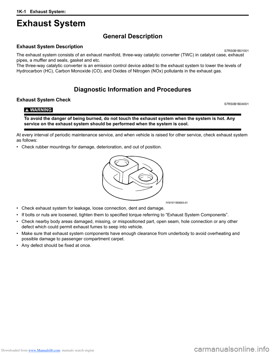
• Check rubber mountings for damage, deterioration, and out of position.
• Check exhaust system for leakage, loose connection, dent and damage.
• If bolts or nuts are loosened, tighten them to specified torque referring to “Exhaust System Components”.
• Check nearby body areas damaged, missing, or mispositio ned part, open seam, hole connection or any other
defect which could permit exhaust fumes to seep into vehicle.
• Make sure that exhaust system components have enough clearance from underbody to avoid overheating and
possible damage to passenger compartment carpet.
• Any defect should be fixed at once.
IYSY011B0003-01
Page 579 of 1496
Downloaded from www.Manualslib.com manuals search engine Electronic Stability Program: 4F-5
Yaw rate / G sensor
The yaw rate / G sensor consists of the yaw rate (angular velocity in the vehicle turning direction) sensor and right-left
G (acceleration in right-left direction) sensor and is mounted to the P/S controller B/K at the lower part of the center
console. It detects the angular velocity in the vehicle turn ing direction and movement in the right-left direction, and
then it sends that information to ESP ® control module.
Wheel speed sensor
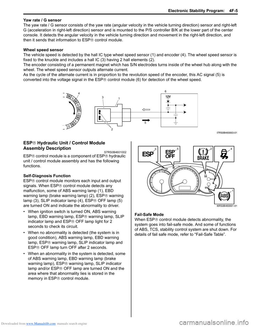
The vehicle speed is detected by the hall IC type wheel speed sensor (1) and encoder (4). The wheel speed sensor is
fixed to the knuckle and includes a hall IC (3) having 2 hall elements (2).
The encoder consisting of a permanent ma gnet which has S/N electrodes turns inside of the wheel hub along with the
wheel. The wheel speed sensor outputs alternate current.
As the cycle of the alternate current is in proportion to the revolution speed of the encoder, this AC signal (5) is
converted into the voltage signal in the ESP ® control module (6) for detection of the wheel speed.
ESP ® Hydraulic Unit / Control Module
Assembly Description
S7RS0B4601002
ESP ® control module is a component of ESP ® hydraulic
unit / control module assembly and has the following
functions.
Self-Diagnosis Function
ESP ® control module monitors each input and output
signals. When ESP ® control module detects any
malfunction, some of ABS warning lamp (1), EBD
warning lamp (brake warning lamp) (2), ESP ® warning
lamp (3), SLIP indicator lamp (4), ESP ® OFF lamp (5)
are turned ON and indicate the abnormality to driver.
• When ignition switch is turned ON, ABS warning lamp, EBD warning lamp, ESP ® warning lamp, SLIP
indicator lamp and ESP ® OFF lamp light for 2
seconds to check its circuit.
• When no abnormality is detected (the system is in good condition), ABS warning lamp, EBD warning
lamp, ESP ® warning lamp, SLIP indicator lamp and
ESP ® OFF lamp turn OFF after 2 seconds.
• When an abnormality in the system is detected, some of ABS warning lamp, EBD warning lamp (brake
warning lamp), ESP ® warning lamp, SLIP indicator
lamp and/or ESP ® OFF lamp are turned ON and the
area where that abnormality lies is stored in the
memory in ESP ® control module. Fail-Safe Mode
When ESP
® control module detects abnormality, the
system goes into fail-safe mode. And some of functions
of ABS, TCS, stability control system are shut down. For
details of fail safe mode, re fer to “Fail-Safe Table”.
S
N
S
N
S
N
N
S
N
S
12V
2
3
1
5
4
6I7RS0B460003-01
3245
1
I6RS0B460001-01
Page 649 of 1496
Downloaded from www.Manualslib.com manuals search engine Automatic Transmission/Transaxle: 5A-5
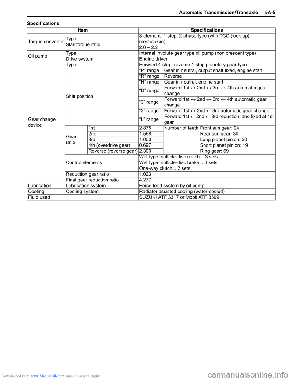
SpecificationsItem Specifications
Torque converter Ty p e
Stall torque ratio 3-element, 1-step, 2-phase type (with TCC (lock-up)
mechanism)
2.0 – 2.2
Oil pump Ty p e
Drive system Internal involute gear type oil pump (non crescent type)
Engine driven
Gear change
device Type Forward 4-step, reverse 1-step planetary gear type
Shift position
“P” range Gear in neutral, output shaft fixed, engine start
“R” range Reverse
“N” range Gear in neutral, engine start
“D” range
Forward 1st
↔ 2nd ↔ 3rd ↔ 4th automatic gear
change
“3” range Forward 1st
↔ 2nd ↔ 3rd ← 4th automatic gear
change
“2” range Forward 1st ↔ 2nd ← 3rd automatic gear change
“L” range Forward 1st
← 2nd ← 3rd reduction, and fixed at 1st
gear
Gear
ratio 1st 2.875 Number of teeth Front sun gear: 24
2nd 1.568 Rear sun gear: 30
3rd 1.000 Long planet pinion: 20
4th (overdrive gear) 0.697 Short planet pinion: 19
Reverse (reverse gear) 2.300 Ring gear: 69
Control elements Wet type multiple-disc clutch... 3 sets
Wet type multiple-d
isc brake... 3 sets
One-way clutch... 2 sets
Reduction gear ratio 1.023
Final gear reduction ratio 4.277
Lubrication Lubrication system Force feed system by oil pump
Cooling Cooling system Radiator assisted cooling (water-cooled)
Fluid used SUZUKI ATF 3317 or Mobil ATF 3309
Page 665 of 1496
Downloaded from www.Manualslib.com manuals search engine Automatic Transmission/Transaxle: 5A-21
Fail-Safe TableS7RS0B5104008
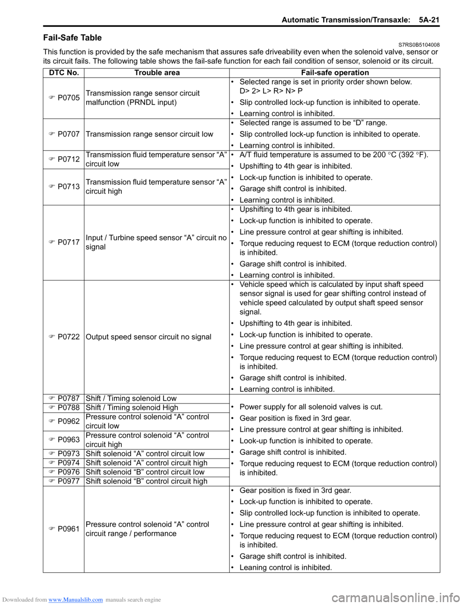
This function is provided by the safe mechanism that assures safe driveability even when the solenoid valve, sensor or
its circuit fails. The following table shows th e fail-safe function for each fail condition of sensor, solenoid or its circuit.
DTC No. Trouble area Fail-safe operation
�) P0705 Transmission range sensor circuit
malfunction (PRNDL input) • Selected range is set in priority order shown below.
D> 2> L> R> N> P
• Slip controlled lock-up function is inhibited to operate.
• Learning control is inhibited.
�) P0707 Transmission range sensor circuit low • Selected range is assumed to be “D” range.
• Slip controlled lock-up function is inhibited to operate.
• Learning control is inhibited.
�) P0712 Transmission fluid temperature sensor “A”
circuit low • A/T fluid temperature is assumed to be 200
°C (392 °F).
• Upshifting to 4th gear is inhibited.
• Lock-up function is inhibited to operate.
• Garage shift control is inhibited.
• Learning control is inhibited.
�)
P0713 Transmission fluid temperature sensor “A”
circuit high
�) P0717 Input / Turbine speed sensor “A” circuit no
signal • Upshifting to 4th gear is inhibited.
• Lock-up function is inhibited to operate.
• Line pressure control at gear shifting is inhibited.
• Torque reducing request to ECM (torque reduction control)
is inhibited.
• Garage shift control is inhibited.
• Learning control is inhibited.
�) P0722 Output speed sensor circuit no signal • Vehicle speed which is calculated by input shaft speed
sensor signal is used for gear shifting control instead of
vehicle speed calculated by output shaft speed sensor
signal.
• Upshifting to 4th gear is inhibited.
• Lock-up function is inhibited to operate.
• Line pressure control at gear shifting is inhibited.
• Torque reducing request to ECM (torque reduction control) is inhibited.
• Garage shift control is inhibited.
• Learning control is inhibited.
�) P0787 Shift / Timing solenoid Low
• Power supply for all solenoid valves is cut.
• Gear position is fixed in 3rd gear.
• Line pressure control at gear shifting is inhibited.
• Look-up function is inhibited to operate.
• Garage shift control is inhibited.
• Torque reducing request to ECM (torque reduction control)
is inhibited.
�)
P0788 Shift / Timing solenoid High
�) P0962 Pressure control solenoid “A” control
circuit low
�) P0963 Pressure control solenoid “A” control
circuit high
�) P0973 Shift solenoid “A” control circuit low
�) P0974 Shift solenoid “A” control circuit high
�) P0976 Shift solenoid “B” control circuit low
�) P0977 Shift solenoid “B” control circuit high
�) P0961 Pressure control solenoid “A” control
circuit range / performance • Gear position is fixed in 3rd gear.
• Lock-up function is inhibited to operate.
• Slip controlled lock-up function is inhibited to operate.
• Line pressure control at gear shifting is inhibited.
• Torque reducing request to ECM (torque reduction control)
is inhibited.
• Garage shift control is inhibited.
• Leaning control is inhibited.
Page 666 of 1496
Downloaded from www.Manualslib.com manuals search engine 5A-22 Automatic Transmission/Transaxle:
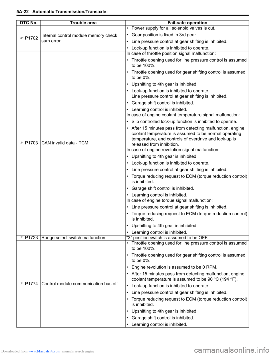
�) P1702 Internal control module memory check
sum error • Power supply for all solenoid valves is cut.
• Gear position is fixed in 3rd gear.
• Line pressure control at gear shifting is inhibited.
• Lock-up function is inhibited to operate.
�) P1703 CAN invalid data - TCM In case of throttle position signal malfunction:
• Throttle opening used for line pressure control is assumed
to be 100%.
• Throttle opening used for gear shifting control is assumed to be 0%.
• Upshifting to 4th gear is inhibited.
• Lock-up function is inhibited to operate. Line pressure control at gear shifting is inhibited.
• Garage shift control is inhibited.
• Learning control is inhibited.
In case of engine coolant temperature signal malfunction:
• Slip controlled lock-up function is inhibited to operate.
• After 15 minutes pass from detecting malfunction, engine coolant temperature is assumed to be normal operating
temperature, and controls of overdrive and lock-up is
released from inhibition.
In case of engine revolution signal malfunction:
• Upshifting to 4th gear is inhibited.
• Lock-up function is inhibited to operate.
• Line pressure control at gear shifting is inhibited.
• Torque reducing request to ECM (torque reduction control) is inhibited.
• Garage shift control is inhibited.
• Learning control is inhibited.
In case of engine torque signal malfunction:
• Line pressure control at gear shifting is inhibited.
• Torque reducing request to ECM (torque reduction control) is inhibited.
• Upshifting to 4th gear is inhibited.
• Learning control is inhibited.
�) P1723 Range select switch malfunction “3” position switch is assumed to be OFF.
�) P1774 Control module communication bus off • Throttle opening used for line pressure control is assumed
to be 100%.
• Throttle opening used for gear shifting control is assumed to be 0%.
• Engine revolution is assumed to be 0 RPM.
• After 15 minutes pass from detecting malfunction, engine coolant temperature is assumed to be 90 °C (194 °F).
• Lock-up function is inhibited to operate.
• Line pressure control at gear shifting is inhibited.
• Torque reducing request to ECM (torque reduction control) is inhibited.
• Upshifting to 4th gear is inhibited.
• Garage shift control is inhibited.
• Learning control is inhibited.
DTC No. Trouble area Fail-safe operation
Page 667 of 1496
Downloaded from www.Manualslib.com manuals search engine Automatic Transmission/Transaxle: 5A-23
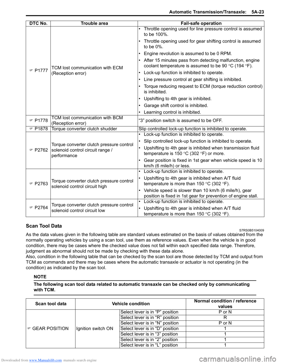
Scan Tool DataS7RS0B5104009
As the data values given in the following table are standard values estimated on the basis of values obtained from the
normally operating vehicles by using a scan tool, use them as reference values. Even when the vehicle is in good
condition, there may be cases where the checked value does not fall within each specified data range. Therefore,
judgment as abnormal should not be made by checking with these data alone.
Also, condition in the following table that can be checked by the scan tool are those detected by TCM and output from
TCM as commands and there may be cases where the auto matic transaxle or actuator is not operating (in the
condition) as indicated by the scan tool.
NOTE
The following scan tool data related to automatic transaxle can be checked only by communicating
with TCM.
�) P1777 TCM lost communication with ECM
(Reception error) • Throttle opening used for line pressure control is assumed
to be 100%.
• Throttle opening used for gear shifting control is assumed to be 0%.
• Engine revolution is assumed to be 0 RPM.
• After 15 minutes pass from detecting malfunction, engine coolant temperature is assumed to be 90 °C (194 °F).
• Lock-up function is inhibited to operate.
• Line pressure control at gear shifting is inhibited.
• Torque reducing request to ECM (torque reduction control) is inhibited.
• Upshifting to 4th gear is inhibited.
• Garage shift control is inhibited.
• Learning control is inhibited.
�) P1778 TCM lost communication with BCM
(Reception error) “3” position switch is assumed to be OFF.
�) P1878 Torque converter clutch shudder Slip contro lled lock-up function is inhibited to operate.
�) P2762 Torque converter clutch pressure control
solenoid control circuit range /
performance • Lock-up function is inhibited to operate.
• Slip controlled lock-up function is inhibited to operate.
• Upshifting to 4th gear is inhibited when transmission fluid
temperature is 150 °C (302 ° F) or more.
• Gear position is fixed in 1st gear when vehicle speed is 10 km/h (6 mile/h) or less.
�) P2763 Torque converter clutch pressure control
solenoid control circuit high • Lock-up function is inhibited to operate.
• Upshifting to 4th gear is inhibited when A/T fluid
temperature is more than 150 °C (302 °F).
• Vehicle speed is slower than 10 km/h (6 mile/h), gear position is fixed in 1st gear for prevention of engine stall.
�) P2764 Torque converter clutch pressure control
solenoid control circuit low • Lock-up function is inhibited to operate.
• Upshifting to 4th gear is inhibited when A/T fluid
temperature is more than 150 °C (302 °F).
DTC No. Trouble area Fail-safe operation
Scan tool data
Vehicle condition Normal condition / reference
values
�) GEAR POSITION Ignition switch ON Select lever is in “P” position
P or N
Select lever is in “R” position R
Select lever is in “N” position P or N
Select lever is in “D” position 1
Select lever is in “3” position 1
Select lever is in “2” position 1
Select lever is in “L” position 1
Page 673 of 1496
Downloaded from www.Manualslib.com manuals search engine Automatic Transmission/Transaxle: 5A-29
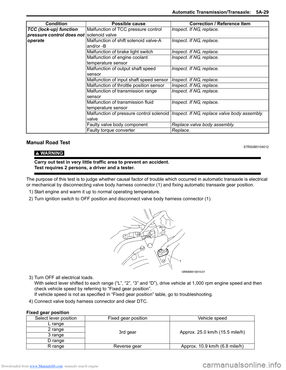
Manual Road TestS7RS0B5104012
WARNING!
Carry out test in very little traffic area to prevent an accident.
Test requires 2 persons, a driver and a tester.
The purpose of this test is to judge whether causal factor of trouble which occurred in automatic transaxle is electrical
or mechanical by disconnecting valve body harness co nnector (1) and fixing automatic transaxle gear position.
1) Start engine and warm it up to normal operating temperature.
2) Turn ignition switch to OFF position and disconnect valve body harness connector (1).
3) Turn OFF all electrical loads. With select lever shifted to each ra nge (“L”, “2”, “3” and “D”), drive vehi cle at 1,000 rpm engine speed and then
check vehicle speed by referring to “Fixed gear position”.
If vehicle speed is not as specified in “Fix ed gear position” table, go to troubleshooting.
4) Connect valve body harness connector and clear DTC.
Fixed gear position TCC (lock-up) function
pressure control does not
operate
Malfunction of TCC pressure control
solenoid valve
Inspect. If NG, replace.
Malfunction of shif t solenoid valve-A
and/or -B Inspect. If NG, replace.
Malfunction of brake light switch Inspect. If NG, replace.
Malfunction of engine coolant
temperature sensor Inspect. If NG, replace.
Malfunction of output shaft speed
sensor Inspect. If NG, replace.
Malfunction of input shaft speed sensor Inspect. If NG, replace.
Malfunction of throttle position sensor Inspect. If NG, replace.
Malfunction of transmission range
sensor Inspect. If NG, replace.
Malfunction of transmission fluid
temperature sensor Inspect. If NG, replace.
Malfunction of pressure control solenoid
valve Inspect. If NG, replace valve body assembly.
Faulty valve body component Replace valve body assembly.
Faulty torque converter Replace.
Condition
Possible cause Correction / Reference Item
Select lever positionFixed gear position Vehicle speed
L range
3rd gearApprox. 25.0 km/h (15.5 mile/h)
2 range
3 range
D range
R range Reverse gear Approx. 10.9 km/h (6.8 mile/h)
I3RM0B510010-01
Page 879 of 1496
Downloaded from www.Manualslib.com manuals search engine Steering Wheel and Column: 6B-8
Installation
CAUTION!
After tightening steering column mounting
nuts, shaft joint bolts should be tightened.
Wrong tightening order could cause a
damage to shaft joint.
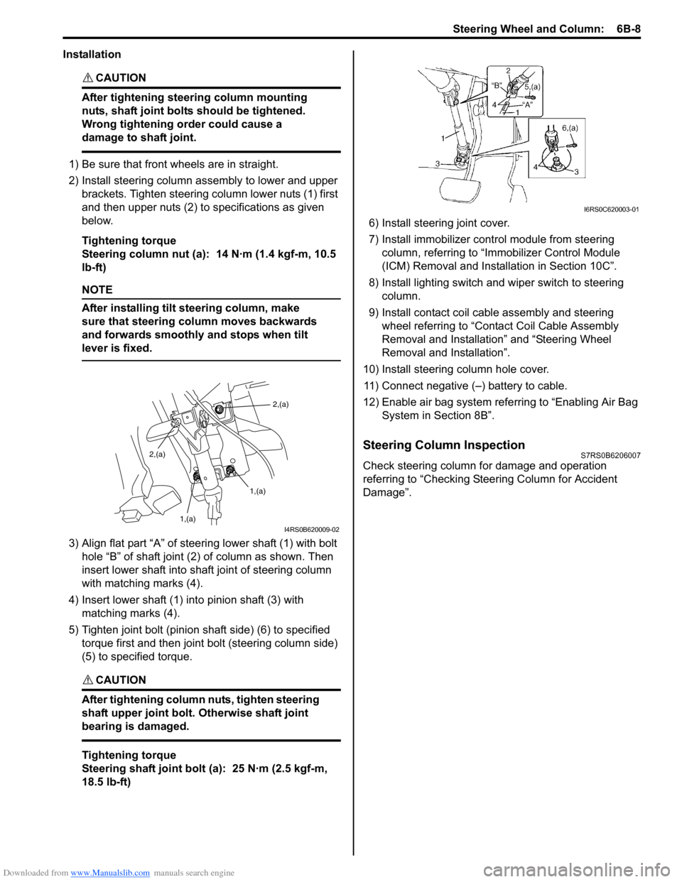
1) Be sure that front wheels are in straight.
2) Install steering column assembly to lower and upper brackets. Tighten steering column lower nuts (1) first
and then upper nuts (2) to specifications as given
below.
Tightening torque
Steering column nut (a): 14 N·m (1.4 kgf-m, 10.5
lb-ft)
NOTE
After installing tilt steering column, make
sure that steering column moves backwards
and forwards smoothly and stops when tilt
lever is fixed.
3) Align flat part “A” of stee ring lower shaft (1) with bolt
hole “B” of shaft joint (2) of column as shown. Then
insert lower shaft into shaf t joint of steering column
with matching marks (4).
4) Insert lower shaft (1) into pinion shaft (3) with matching marks (4).
5) Tighten joint bolt (pinion shaft side) (6) to specified torque first and then joint bolt (steering column side)
(5) to specified torque.
CAUTION!
After tightening column nuts, tighten steering
shaft upper joint bolt. Otherwise shaft joint
bearing is damaged.
Tightening torque
Steering shaft joint bolt (a): 25 N·m (2.5 kgf-m,
18.5 lb-ft) 6) Install steering joint cover.
7) Install immobilizer cont
rol module from steering
column, referring to “Immo bilizer Control Module
(ICM) Removal and Installation in Section 10C”.
8) Install lighting switch and wiper switch to steering column.
9) Install contact coil cable assembly and steering wheel referring to “Conta ct Coil Cable Assembly
Removal and Installation” and “Steering Wheel
Removal and Installation”.
10) Install steering column hole cover. 11) Connect negative (–) battery to cable.
12) Enable air bag system refe rring to “Enabling Air Bag
System in Section 8B”.
Steering Column InspectionS7RS0B6206007
Check steering column for damage and operation
referring to “Checking Steering Column for Accident
Damage”.
2,(a)
1,(a)
1,(a)
2,(a)
I4RS0B620009-02
I6RS0C620003-01