2006 SUZUKI SWIFT ECM power supply
[x] Cancel search: ECM power supplyPage 110 of 1496
Downloaded from www.Manualslib.com manuals search engine 1A-60 Engine General Information and Diagnosis:
4MAF sensor output voltage check
1) Turn OFF ignition switch.
2) Remove ECM from its br acket with ECM connectors
connected.
3) Measure voltage between “C37-26” and “C37-27” terminals of ECM connector referring to “MAF and IAT
Sensor On-Vehicle Inspection in Section 1C”.
Is each value within specified range? Poor “C37-26” and/or
“C37-27” terminal
connection.
If OK, substitute a
known-good ECM and
recheck.
Go to Step 5.
5 MAF sensor power supply voltage check
1) Disconnect connector from MAF and IAT sensor with
ignition switch turned OFF.
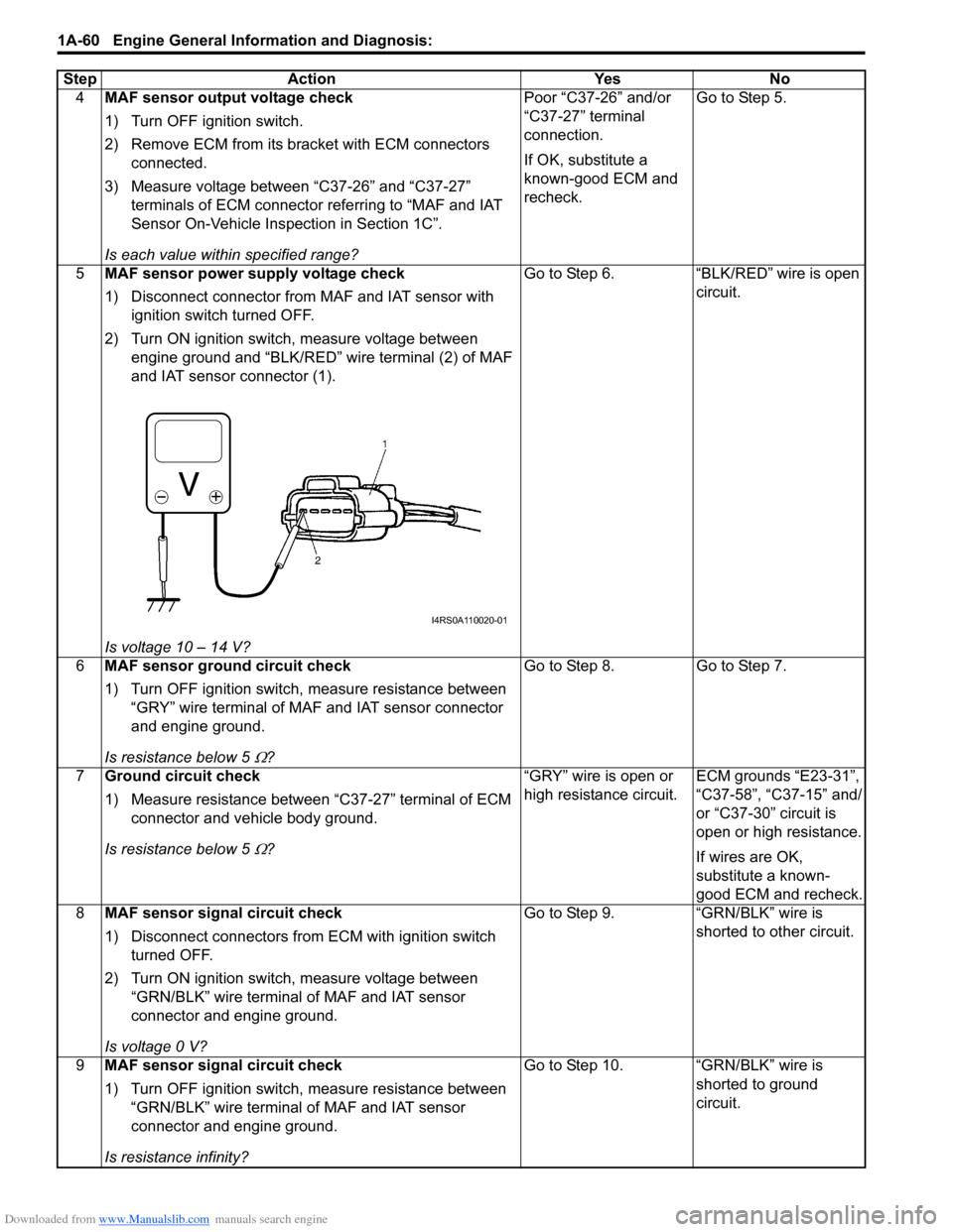
2) Turn ON ignition switch, measure voltage between engine ground and “BLK/RED” wire terminal (2) of MAF
and IAT sensor connector (1).
Is voltage 10 – 14 V? Go to Step 6. “BLK/RED” wire is open
circuit.
6 MAF sensor ground circuit check
1) Turn OFF ignition switch, measure resistance between
“GRY” wire terminal of MAF and IAT sensor connector
and engine ground.
Is resistance below 5
Ω? Go to Step 8.
Go to Step 7.
7 Ground circuit check
1) Measure resistance between “C37-27” terminal of ECM
connector and vehicle body ground.
Is resistance below 5
Ω? “GRY” wire is open or
high resistance circuit.
ECM grounds “E23-31”,
“C37-58”, “C37-15” and/
or “C37-30” circuit is
open or high resistance.
If wires are OK,
substitute a known-
good ECM and recheck.
8 MAF sensor signal circuit check
1) Disconnect connectors from ECM with ignition switch
turned OFF.
2) Turn ON ignition switch, measure voltage between “GRN/BLK” wire terminal of MAF and IAT sensor
connector and engine ground.
Is voltage 0 V? Go to Step 9. “GRN/BLK” wire is
shorted to other circuit.
9 MAF sensor signal circuit check
1) Turn OFF ignition switch, measure resistance between
“GRN/BLK” wire terminal of MAF and IAT sensor
connector and engine ground.
Is resistance infinity? Go to Step 10. “GRN/BLK” wire is
shorted to ground
circuit.
Step Action Yes No
I4RS0A110020-01
Page 112 of 1496
Downloaded from www.Manualslib.com manuals search engine 1A-62 Engine General Information and Diagnosis:
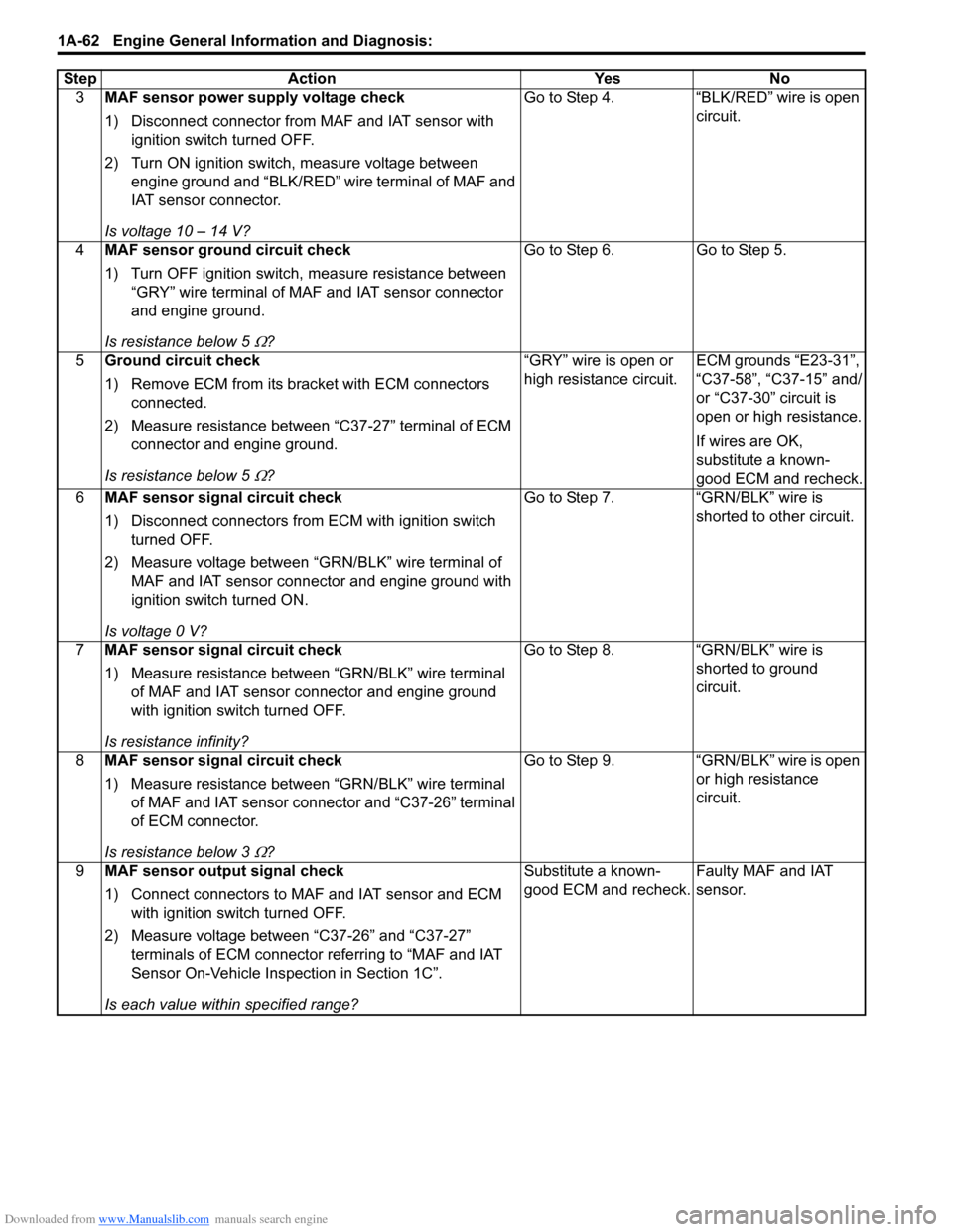
3MAF sensor power supply voltage check
1) Disconnect connector from MAF and IAT sensor with
ignition switch turned OFF.
2) Turn ON ignition switch, measure voltage between engine ground and “BLK/RED” wire terminal of MAF and
IAT sensor connector.
Is voltage 10 – 14 V? Go to Step 4. “BLK/RED” wire is open
circuit.
4 MAF sensor ground circuit check
1) Turn OFF ignition switch, measure resistance between
“GRY” wire terminal of MAF and IAT sensor connector
and engine ground.
Is resistance below 5
Ω? Go to Step 6.
Go to Step 5.
5 Ground circuit check
1) Remove ECM from its br acket with ECM connectors
connected.
2) Measure resistance between “C37-27” terminal of ECM connector and engine ground.
Is resistance below 5
Ω? “GRY” wire is open or
high resistance circuit.
ECM grounds “E23-31”,
“C37-58”, “C37-15” and/
or “C37-30” circuit is
open or high resistance.
If wires are OK,
substitute a known-
good ECM and recheck.
6 MAF sensor signal circuit check
1) Disconnect connectors from ECM with ignition switch
turned OFF.
2) Measure voltage between “GRN/BLK” wire terminal of MAF and IAT sensor connector and engine ground with
ignition switch turned ON.
Is voltage 0 V? Go to Step 7. “GRN/BLK” wire is
shorted to other circuit.
7 MAF sensor signal circuit check
1) Measure resistance between “GRN/BLK” wire terminal
of MAF and IAT sensor connector and engine ground
with ignition swit ch turned OFF.
Is resistance infinity? Go to Step 8.
“GRN/BLK” wire is
shorted to ground
circuit.
8 MAF sensor signal circuit check
1) Measure resistance between “GRN/BLK” wire terminal
of MAF and IAT sensor connector and “C37-26” terminal
of ECM connector.
Is resistance below 3
Ω? Go to Step 9.
“GRN/BLK” wire is open
or high resistance
circuit.
9 MAF sensor output signal check
1) Connect connectors to MAF and IAT sensor and ECM
with ignition swit ch turned OFF.
2) Measure voltage between “C37-26” and “C37-27” terminals of ECM connector referring to “MAF and IAT
Sensor On-Vehicle Inspection in Section 1C”.
Is each value within specified range? Substitute a known-
good ECM and recheck.
Faulty MAF and IAT
sensor.
Step
Action YesNo
Page 113 of 1496
Downloaded from www.Manualslib.com manuals search engine Engine General Information and Diagnosis: 1A-63
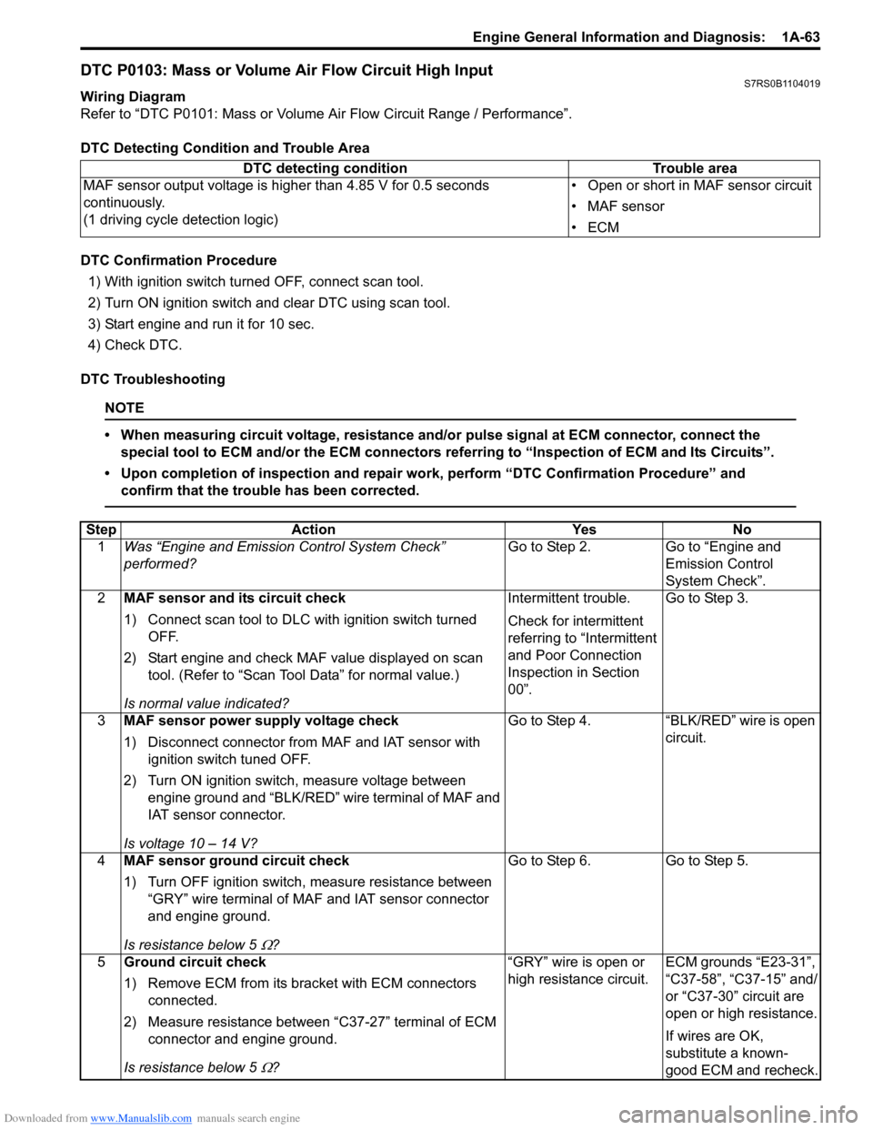
DTC P0103: Mass or Volume Air Flow Circuit High InputS7RS0B1104019
Wiring Diagram
Refer to “DTC P0101: Mass or Volume Air Flow Circuit Range / Performance”.
DTC Detecting Condition and Trouble Area
DTC Confirmation Procedure1) With ignition switch turned OFF, connect scan tool.
2) Turn ON ignition switch and clear DTC using scan tool.
3) Start engine and run it for 10 sec.
4) Check DTC.
DTC Troubleshooting
NOTE
• When measuring circuit voltage, resistance and/ or pulse signal at ECM connector, connect the
special tool to ECM and/or the ECM connectors re ferring to “Inspection of ECM and Its Circuits”.
• Upon completion of inspection and repair work, perform “DTC Confirmation Procedure” and confirm that the trouble has been corrected.
DTC detecting condition Trouble area
MAF sensor output voltage is higher than 4.85 V for 0.5 seconds
continuously.
(1 driving cycle detection logic) • Open or short in MAF sensor circuit
• MAF sensor
•ECM
Step
Action YesNo
1 Was “Engine and Emission Control System Check”
performed? Go to Step 2.
Go to “Engine and
Emission Control
System Check”.
2 MAF sensor and its circuit check
1) Connect scan tool to DLC with ignition switch turned
OFF.
2) Start engine and check MAF value displayed on scan tool. (Refer to “Scan Tool Data” for normal value.)
Is normal value indicated? Intermittent trouble.
Check for intermittent
referring to “Intermittent
and Poor Connection
Inspection in Section
00”.
Go to Step 3.
3 MAF sensor power supply voltage check
1) Disconnect connector from MAF and IAT sensor with
ignition switch tuned OFF.
2) Turn ON ignition switch, measure voltage between engine ground and “BLK/RED” wire terminal of MAF and
IAT sensor connector.
Is voltage 10 – 14 V? Go to Step 4.
“BLK/RED” wire is open
circuit.
4 MAF sensor ground circuit check
1) Turn OFF ignition switch, measure resistance between
“GRY” wire terminal of MAF and IAT sensor connector
and engine ground.
Is resistance below 5
Ω? Go to Step 6. Go to Step 5.
5 Ground circuit check
1) Remove ECM from its br acket with ECM connectors
connected.
2) Measure resistance between “C37-27” terminal of ECM connector and engine ground.
Is resistance below 5
Ω? “GRY” wire is open or
high resistance circuit.
ECM grounds “E23-31”,
“C37-58”, “C37-15” and/
or “C37-30” circuit are
open or high resistance.
If wires are OK,
substitute a known-
good ECM and recheck.
Page 116 of 1496
Downloaded from www.Manualslib.com manuals search engine 1A-66 Engine General Information and Diagnosis:
DTC P0107: Manifold Absolute Pressure / Barometric Pressure Circuit Low InputS7RS0B1104021
Wiring Diagram
Refer to “DTC P0106: Manifold Absolute Pressure / Barometric Pressure Circuit Range / Performance”
DTC Detecting Condition and Trouble Area
DTC Confirmation Procedure 1) Connect scan tool to DLC with ignition switch turned OFF.
2) Turn ON ignition switch and clear DTC using scan tool.
3) Run engine at idle speed for 1 min.
4) Check DTC.
DTC Troubleshooting
NOTE
• When measuring circuit voltage, resistance and/ or pulse signal at ECM connector, connect the
special tool to ECM and/or the ECM connectors re ferring to “Inspection of ECM and Its Circuits”.
• Upon completion of inspection and repair work, perform “DTC Confirmation Procedure” and confirm that the trouble has been corrected.
DTC detecting condition Trouble area
Manifold absolute pressure se nsor output voltage is lower
than specified value for s pecified time continuously.
(1 driving cycle detection logic) • Manifold absolute pressure sensor circuit
• Manifold absolute pressure sensor
• A/C refrigerant pressure sensor (if equipped with A/C)
•ECM
Step
Action YesNo
1 Was “Engine and Emission Control System Check”
performed? Go to Step 2.
Go to “Engine and
Emission Control
System Check”.
2 MAP sensor and its circuit check
1) Connect scan tool to DLC with ignition switch turned
OFF.
2) Turn ON ignition switch.
3) Check intake manifold pressure displayed on scan tool.
Is it 0 kPa (0 in.Hg)? Go to Step 3.
Intermittent trouble.
Check for intermittent
referring to “Intermittent
and Poor Connection
Inspection in Section
00”.
3 MAP sensor power supply voltage check
1) Disconnect connector from MAP sensor with ignition
switch turned OFF.
2) Check for proper connection of MAP sensor at “GRY/ RED”, “RED/BLK” and “ORN” wire terminals.
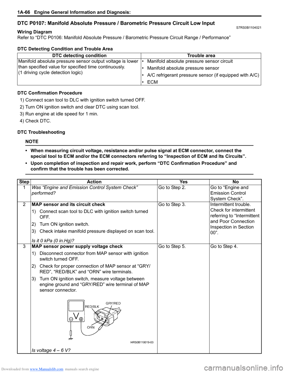
3) Turn ON ignition switch, measure voltage between engine ground and “GRY/RED” wire terminal of MAP
sensor connector.
Is voltage 4 – 6 V? Go to Step 5.
Go to Step 4.
I4RS0B110019-03
Page 117 of 1496
Downloaded from www.Manualslib.com manuals search engine Engine General Information and Diagnosis: 1A-67
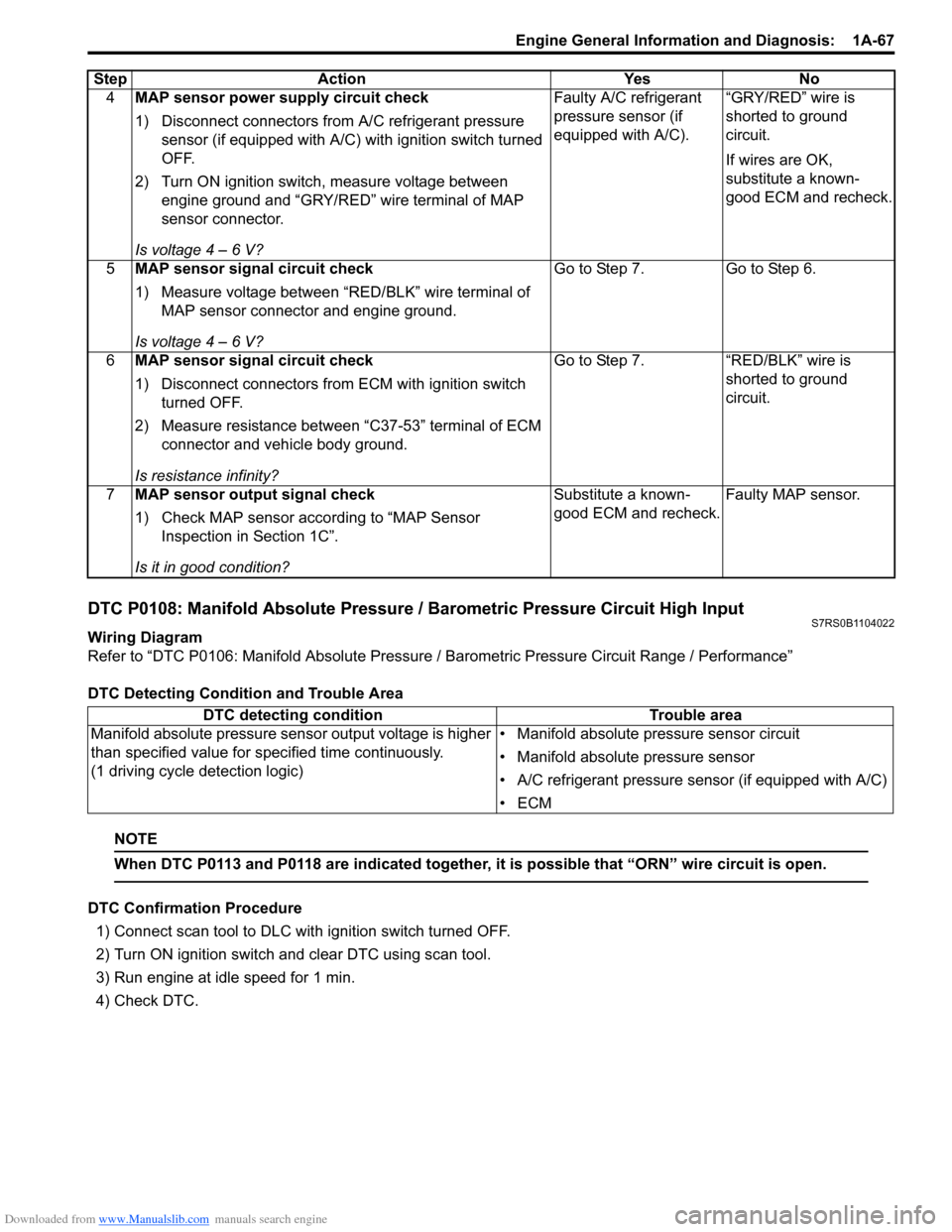
DTC P0108: Manifold Absolute Pressure / Barometric Pressure Circuit High InputS7RS0B1104022
Wiring Diagram
Refer to “DTC P0106: Manifold Absolute Pressure / Barometric Pressure Circuit Range / Performance”
DTC Detecting Condition and Trouble Area
NOTE
When DTC P0113 and P0118 are indicated together, it is possible that “ORN” wire circuit is open.
DTC Confirmation Procedure 1) Connect scan tool to DLC with ignition switch turned OFF.
2) Turn ON ignition switch and clear DTC using scan tool.
3) Run engine at idle speed for 1 min.
4) Check DTC. 4
MAP sensor power supply circuit check
1) Disconnect connectors from A/C refrigerant pressure
sensor (if equipped with A/C) with ignition switch turned
OFF.
2) Turn ON ignition switch, measure voltage between engine ground and “GRY/RED” wire terminal of MAP
sensor connector.
Is voltage 4 – 6 V? Faulty A/C refrigerant
pressure sensor (if
equipped with A/C).
“GRY/RED” wire is
shorted to ground
circuit.
If wires are OK,
substitute a known-
good ECM and recheck.
5 MAP sensor signal circuit check
1) Measure voltage between “RED/BLK” wire terminal of
MAP sensor connector and engine ground.
Is voltage 4 – 6 V? Go to Step 7. Go to Step 6.
6 MAP sensor signal circuit check
1) Disconnect connectors from ECM with ignition switch
turned OFF.
2) Measure resistance between “C37-53” terminal of ECM connector and vehicle body ground.
Is resistance infinity? Go to Step 7. “RED/BLK” wire is
shorted to ground
circuit.
7 MAP sensor output signal check
1) Check MAP sensor acco rding to “MAP Sensor
Inspection in Section 1C”.
Is it in good condition? Substitute a known-
good ECM and recheck.
Faulty MAP sensor.
Step Action Yes No
DTC detecting condition
Trouble area
Manifold absolute pressure sensor output voltage is higher
than specified value for s pecified time continuously.
(1 driving cycle detection logic) • Manifold absolute pressure sensor circuit
• Manifold absolute pressure sensor
• A/C refrigerant pressure sensor (if equipped with A/C)
•ECM
Page 118 of 1496
Downloaded from www.Manualslib.com manuals search engine 1A-68 Engine General Information and Diagnosis:
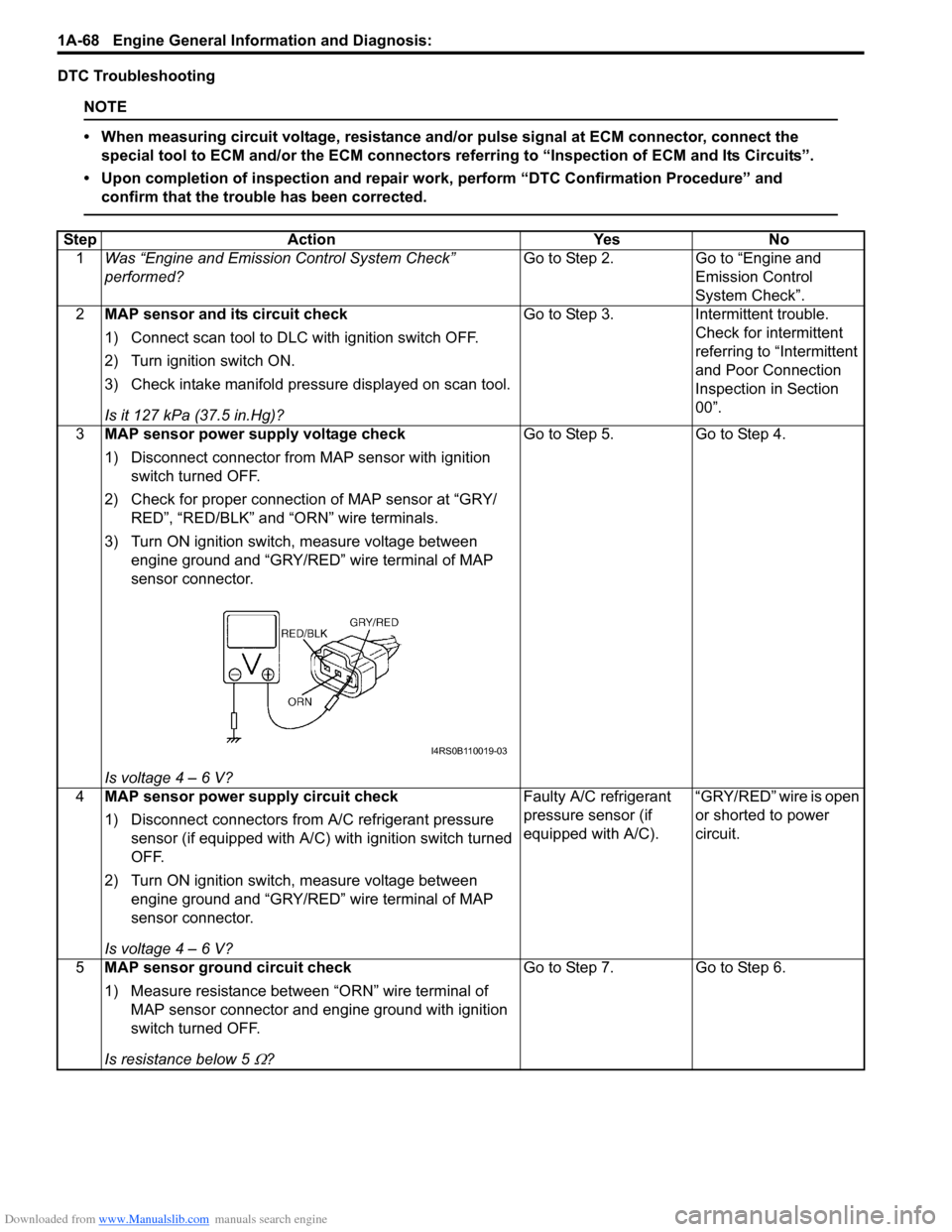
DTC Troubleshooting
NOTE
• When measuring circuit voltage, resistance and/or pulse signal at ECM connector, connect the
special tool to ECM and/or the ECM connectors re ferring to “Inspection of ECM and Its Circuits”.
• Upon completion of inspection and repair work, perform “DTC Confirmation Procedure” and confirm that the trouble has been corrected.
Step Action YesNo
1 Was “Engine and Emission Control System Check”
performed? Go to Step 2.
Go to “Engine and
Emission Control
System Check”.
2 MAP sensor and its circuit check
1) Connect scan tool to DLC with ignition switch OFF.
2) Turn ignition switch ON.
3) Check intake manifold pressure displayed on scan tool.
Is it 127 kPa (37.5 in.Hg)? Go to Step 3.
Intermittent trouble.
Check for intermittent
referring to “Intermittent
and Poor Connection
Inspection in Section
00”.
3 MAP sensor power supply voltage check
1) Disconnect connector from MAP sensor with ignition
switch turned OFF.
2) Check for proper connection of MAP sensor at “GRY/ RED”, “RED/BLK” and “ORN” wire terminals.
3) Turn ON ignition switch, measure voltage between engine ground and “GRY/RED” wire terminal of MAP
sensor connector.
Is voltage 4 – 6 V? Go to Step 5.
Go to Step 4.
4 MAP sensor power supply circuit check
1) Disconnect connectors from A/C refrigerant pressure
sensor (if equipped with A/C) with ignition switch turned
OFF.
2) Turn ON ignition switch, measure voltage between engine ground and “GRY/RED” wire terminal of MAP
sensor connector.
Is voltage 4 – 6 V? Faulty A/C refrigerant
pressure sensor (if
equipped with A/C).
“GRY/RED” wire is open
or shorted to power
circuit.
5 MAP sensor ground circuit check
1) Measure resistance between “ORN” wire terminal of
MAP sensor connector and engine ground with ignition
switch turned OFF.
Is resistance below 5
Ω? Go to Step 7.
Go to Step 6.
I4RS0B110019-03
Page 119 of 1496
Downloaded from www.Manualslib.com manuals search engine Engine General Information and Diagnosis: 1A-69
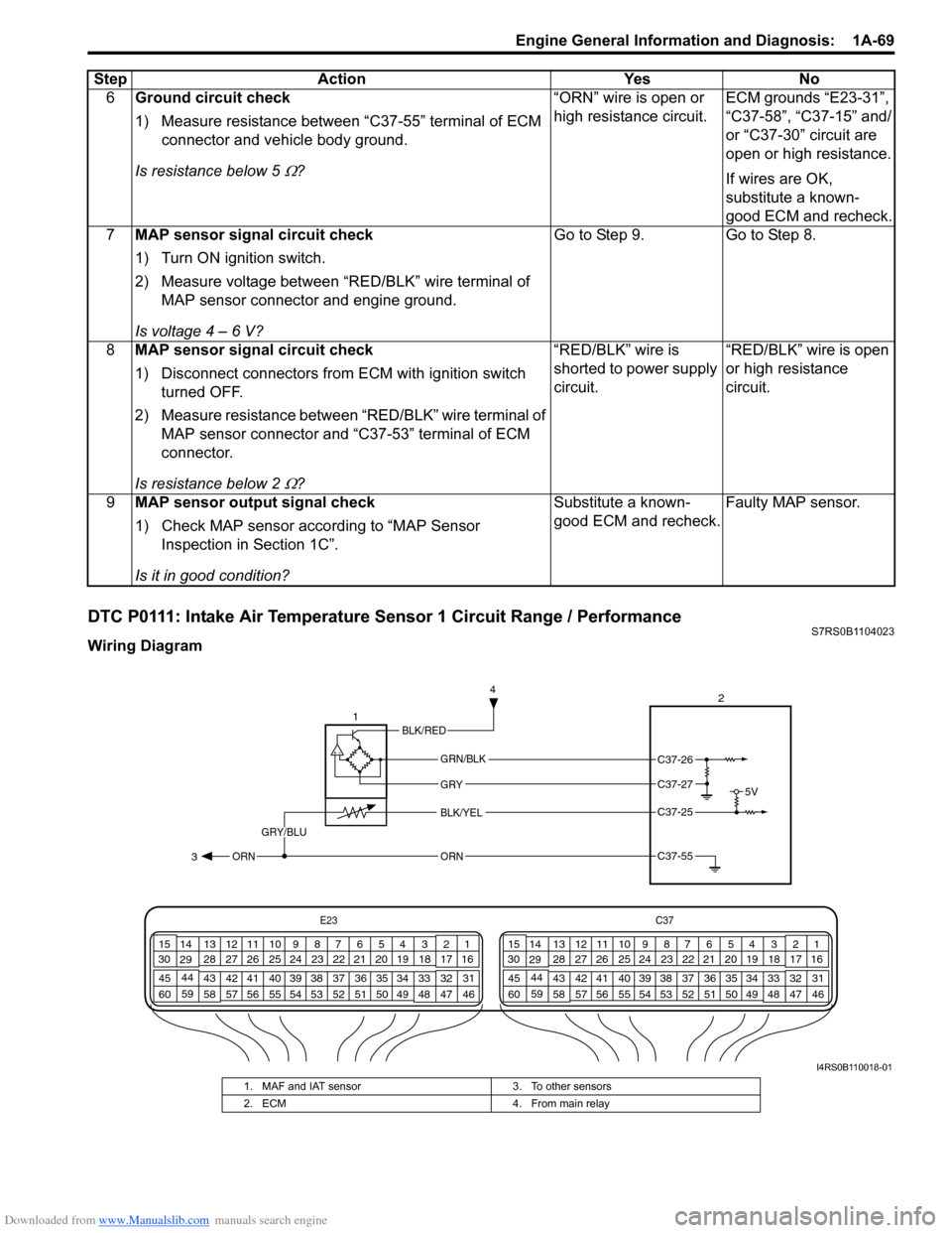
DTC P0111: Intake Air Temperature Sensor 1 Circuit Range / PerformanceS7RS0B1104023
Wiring Diagram6
Ground circuit check
1) Measure resistance between “C37-55” terminal of ECM
connector and vehicle body ground.
Is resistance below 5
Ω? “ORN” wire is open or
high resistance circuit.
ECM grounds “E23-31”,
“C37-58”, “C37-15” and/
or “C37-30” circuit are
open or high resistance.
If wires are OK,
substitute a known-
good ECM and recheck.
7 MAP sensor signal circuit check
1) Turn ON ignition switch.
2) Measure voltage between “RED/BLK” wire terminal of
MAP sensor connector and engine ground.
Is voltage 4 – 6 V? Go to Step 9. Go to Step 8.
8 MAP sensor signal circuit check
1) Disconnect connectors from ECM with ignition switch
turned OFF.
2) Measure resistance between “RED/BLK” wire terminal of MAP sensor connector and “C37-53” terminal of ECM
connector.
Is resistance below 2
Ω? “RED/BLK” wire is
shorted to power supply
circuit.
“RED/BLK” wire is open
or high resistance
circuit.
9 MAP sensor output signal check
1) Check MAP sensor acco rding to “MAP Sensor
Inspection in Section 1C”.
Is it in good condition? Substitute a known-
good ECM and recheck.
Faulty MAP sensor.
Step Action Yes No
E23
C37
34
1819
567
1011
17
20
47 46
495051
2122
52 16
25 9
24
14
29
55
57 54 53
59
60 58 2
262728
15
30
56 4832 31
34353637
40
42 39 38
44
45 43 41 331
1213
238
34
1819
567
1011
17
20
47 46
495051
2122
52 16
25 9
24
14
29
55
57 54 53
59
60 58 2
262728
15
30
56 4832 31
34353637
40
42 39 38
44
45 43 41 331
1213
238
5V
2
BLK/YEL
GRY/BLU
GRY
ORN
1
GRN/BLK
C37-25
C37-55 3 4ORN
C37-26
C37-27
BLK/RED
I4RS0B110018-01
1. MAF and IAT sensor
3. To other sensors
2. ECM 4. From main relay
Page 160 of 1496
Downloaded from www.Manualslib.com manuals search engine 1A-110 Engine General Information and Diagnosis:
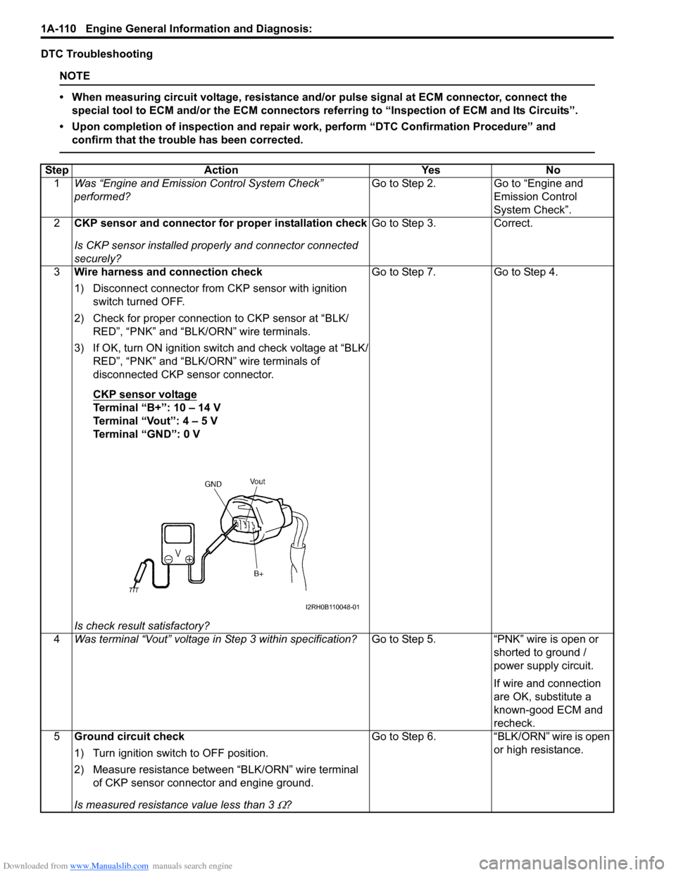
DTC Troubleshooting
NOTE
• When measuring circuit voltage, resistance and/or pulse signal at ECM connector, connect the
special tool to ECM and/or the ECM connectors re ferring to “Inspection of ECM and Its Circuits”.
• Upon completion of inspection and repair work, perform “DTC Confirmation Procedure” and confirm that the trouble has been corrected.
Step Action YesNo
1 Was “Engine and Emission Control System Check”
performed? Go to Step 2.
Go to “Engine and
Emission Control
System Check”.
2 CKP sensor and connector for proper installation check
Is CKP sensor installed properly and connector connected
securely? Go to Step 3.
Correct.
3 Wire harness and connection check
1) Disconnect connector from CKP sensor with ignition
switch turned OFF.
2) Check for proper connection to CKP sensor at “BLK/ RED”, “PNK” and “BLK/ORN” wire terminals.
3) If OK, turn ON ignition switch and check voltage at “BLK/ RED”, “PNK” and “BLK/ORN” wire terminals of
disconnected CKP sensor connector.
CKP sensor voltage
Terminal “B+”: 10 – 14 V
Terminal “Vout”: 4 – 5 V
Terminal “GND”: 0 V
Is check result satisfactory? Go to Step 7. Go to Step 4.
4 Was terminal “Vout” voltage in Step 3 within specification? Go to Step 5. “PNK” wire is open or
shorted to ground /
power supply circuit.
If wire and connection
are OK, substitute a
known-good ECM and
recheck.
5 Ground circuit check
1) Turn ignition switch to OFF position.
2) Measure resistance between “BLK/ORN” wire terminal
of CKP sensor connector and engine ground.
Is measured resistance value less than 3
Ω? Go to Step 6. “BLK/ORN” wire is open
or high resistance.
I2RH0B110048-01