2006 SUZUKI SWIFT ECM ground circuit
[x] Cancel search: ECM ground circuitPage 76 of 1496
Downloaded from www.Manualslib.com manuals search engine 1A-26 Engine General Information and Diagnosis:
DTC CheckS7RS0B1104003
NOTE
• There are two types of OBD system depending on the vehicle specification.
For details, refer to “Precaution on On-
Board Diagnostic (OBD) System”.
• The MIL is turned on when the ECM and/or TCM detect malfunction(s). Each ECM and
TCM stores diagnostic information as the
diagnostic trouble code (DTC) in its
memory and outputs th e DTC to the scan
tool.
Therefore, check both of the ECM and TCM
for any DTC with the SUZUKI scan tool
because the DTC stored in ECM and TCM
is not read and displayed at a time.
However, each of the ECM and TCM needs
not to be checked with the generic scan
tool because the DTC stored in ECM and
TCM is read and displayed at a time.
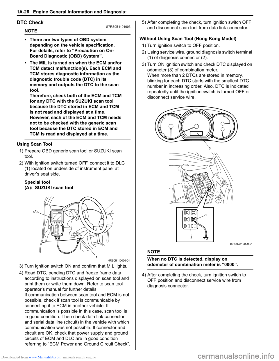
Using Scan Tool
1) Prepare OBD generic scan tool or SUZUKI scan tool.
2) With ignition switch turned OFF, connect it to DLC (1) located on underside of instrument panel at
driver’s seat side.
Special tool
(A): SUZUKI scan tool
3) Turn ignition switch ON and confirm that MIL lights.
4) Read DTC, pending DTC and freeze frame data according to instructions displayed on scan tool and
print them or write them down. Refer to scan tool
operator’s manual for further details.
If communication between scan tool and ECM is not
possible, check if scan tool is communicable by
connecting it to ECM in another vehicle. If
communication is possible in this case, scan tool is
in good condition. Then check data link connector
and serial data line (circuit) in the vehicle with which
communication was not possible. If connector and
circuit are OK, check that power supply and ground
circuits of ECM and DLC are in good condition
referring to “ECM Power and Ground Circuit Check”. 5) After completing the check,
turn ignition switch OFF
and disconnect scan tool from data link connector.
Without Using Scan Tool (Hong Kong Model) 1) Turn ignition switch to OFF position.
2) Using service wire, ground diagnosis switch terminal (1) of diagnosis connector (2).
3) Turn ON ignition switch and check DTC displayed on
odometer (3) of combination meter.
When more than 2 DTCs are stored in memory,
blinking for each DTC star ts with the smallest DTC
number in increasing order. Also, DTC is indicated
repeatedly until the ignition switch is turned OFF or
disconnect service wire.
NOTE
When no DTC is detected, display on
odometer of combinatio n meter is “0000”.
4) After completing the check, turn ignition switch to
OFF position and disconnect service wire from
diagnosis connector.
(A)
1
I4RS0B110026-01
21
3
I5RS0C110009-01
Page 98 of 1496
Downloaded from www.Manualslib.com manuals search engine 1A-48 Engine General Information and Diagnosis:
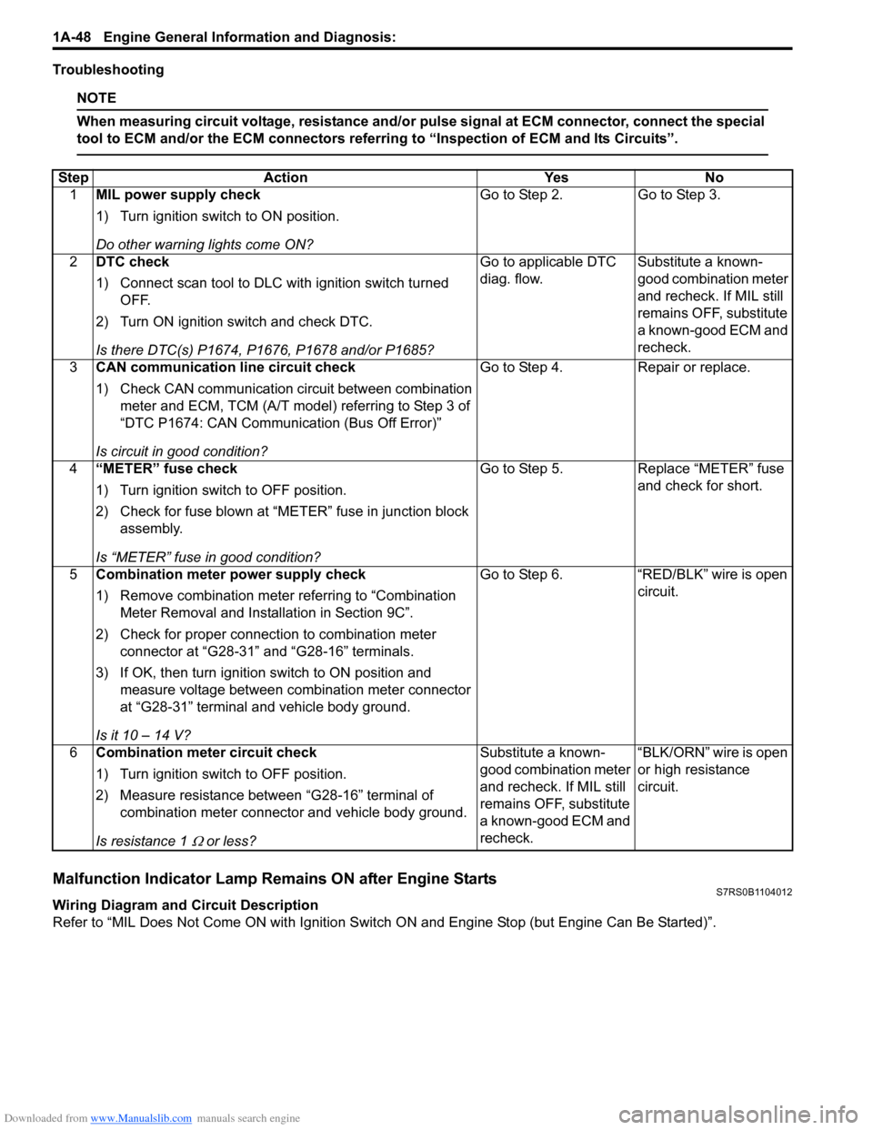
Troubleshooting
NOTE
When measuring circuit voltage, resistance and/or pulse signal at ECM connector, connect the special
tool to ECM and/or the ECM connectors referri ng to “Inspection of ECM and Its Circuits”.
Malfunction Indicator Lamp Remains ON after Engine StartsS7RS0B1104012
Wiring Diagram and Circuit Description
Refer to “MIL Does Not Come ON wit h Ignition Switch ON and Engine Stop (but Engine Can Be Started)”.
Step
Action YesNo
1 MIL power supply check
1) Turn ignition switch to ON position.
Do other warning lights come ON? Go to Step 2.
Go to Step 3.
2 DTC check
1) Connect scan tool to DLC with ignition switch turned
OFF.
2) Turn ON ignition switch and check DTC.
Is there DTC(s) P1674, P1676, P1678 and/or P1685? Go to applicable DTC
diag. flow.
Substitute a known-
good combination meter
and recheck. If MIL still
remains OFF, substitute
a known-good ECM and
recheck.
3 CAN communication line circuit check
1) Check CAN communication circuit between combination
meter and ECM, TCM (A/T model) referring to Step 3 of
“DTC P1674: CAN Communication (Bus Off Error)”
Is circuit in good condition? Go to Step 4.
Repair or replace.
4 “METER” fuse check
1) Turn ignition switch to OFF position.
2) Check for fuse blown at “M ETER” fuse in junction block
assembly.
Is “METER” fuse in good condition? Go to Step 5.
Replace “METER” fuse
and check for short.
5 Combination meter power supply check
1) Remove combination meter referring to “Combination
Meter Removal and Installation in Section 9C”.
2) Check for proper connection to combination meter connector at “G28-31” and “G28-16” terminals.
3) If OK, then turn ignition switch to ON position and measure voltage between combination meter connector
at “G28-31” terminal and vehicle body ground.
Is it 10 – 14 V? Go to Step 6.
“RED/BLK” wire is open
circuit.
6 Combination meter circuit check
1) Turn ignition switch to OFF position.
2) Measure resistance between “G28-16” terminal of
combination meter connector and vehicle body ground.
Is resistance 1
Ω or less? Substitute a known-
good combination meter
and recheck. If MIL still
remains OFF, substitute
a known-good ECM and
recheck.
“BLK/ORN” wire is open
or high resistance
circuit.
Page 100 of 1496
Downloaded from www.Manualslib.com manuals search engine 1A-50 Engine General Information and Diagnosis:
Circuit Description
Actual valve timing fails to become close to target advance level of each function although advance control function or
retarded advance control function is at work.
DTC Detecting Condition and Trouble Area
DTC Confirmation Procedure 1) Clear DTC. Refer to “DTC Clearance”.
2) Start engine and keep it at idle for 10 seconds.
3) Check DTC. Refer to “DTC Check”.
DTC Troubleshooting
NOTE
• When measuring circuit voltage, resistance and/ or pulse signal at ECM connector, connect the
special tool to ECM and/or the ECM connectors re ferring to “Inspection of ECM and Its Circuits”.
• Upon completion of inspection and repair work, perform “DTC Confirmation Procedure” and confirm that the trouble has been corrected.
DTC detecting condition Trouble area
Monitor signal of oil control valve is different from
command signal. (Circuit open or short)
(1 driving cycle detection logic) • Oil control valve
• Oil control valve circuit
•ECM
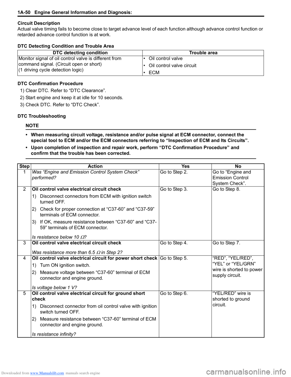
Step
Action YesNo
1 Was “Engine and Emission Control System Check”
performed? Go to Step 2.
Go to “Engine and
Emission Control
System Check”.
2 Oil control valve electrical circuit check
1) Disconnect connectors from ECM with ignition switch
turned OFF.
2) Check for proper connection at “C37-60” and “C37-59” terminals of ECM connector.
3) If OK, measure resistance between “C37-60” and “C37- 59” terminals of ECM connector.
Is resistance below 10
Ω? Go to Step 3. Go to Step 8.
3 Oil control valve electrical circuit check
Was resistance more than 6.5
Ω in Step 2? Go to Step 4. Go to Step 7.
4 Oil control valve electrical circuit for power short check
1) Turn ON ignition switch.
2) Measure voltage between “C37-60” terminal of ECM
connector and engine ground.
Is voltage below 1 V? Go to Step 5. “RED”, “YEL/RED”,
“YEL” or “YEL/GRN”
wire is shorted to power
supply circuit.
5 Oil control valve electrical circuit for ground short
check
1) Disconnect connector from oil control valve with ignition
switch turned OFF.
2) Measure resistance between “C37-60” terminal of ECM connector and engine ground.
Is resistance infinity? Go to Step 6. “YEL/RED” wire is
shorted to ground
circuit.
Page 101 of 1496
Downloaded from www.Manualslib.com manuals search engine Engine General Information and Diagnosis: 1A-51
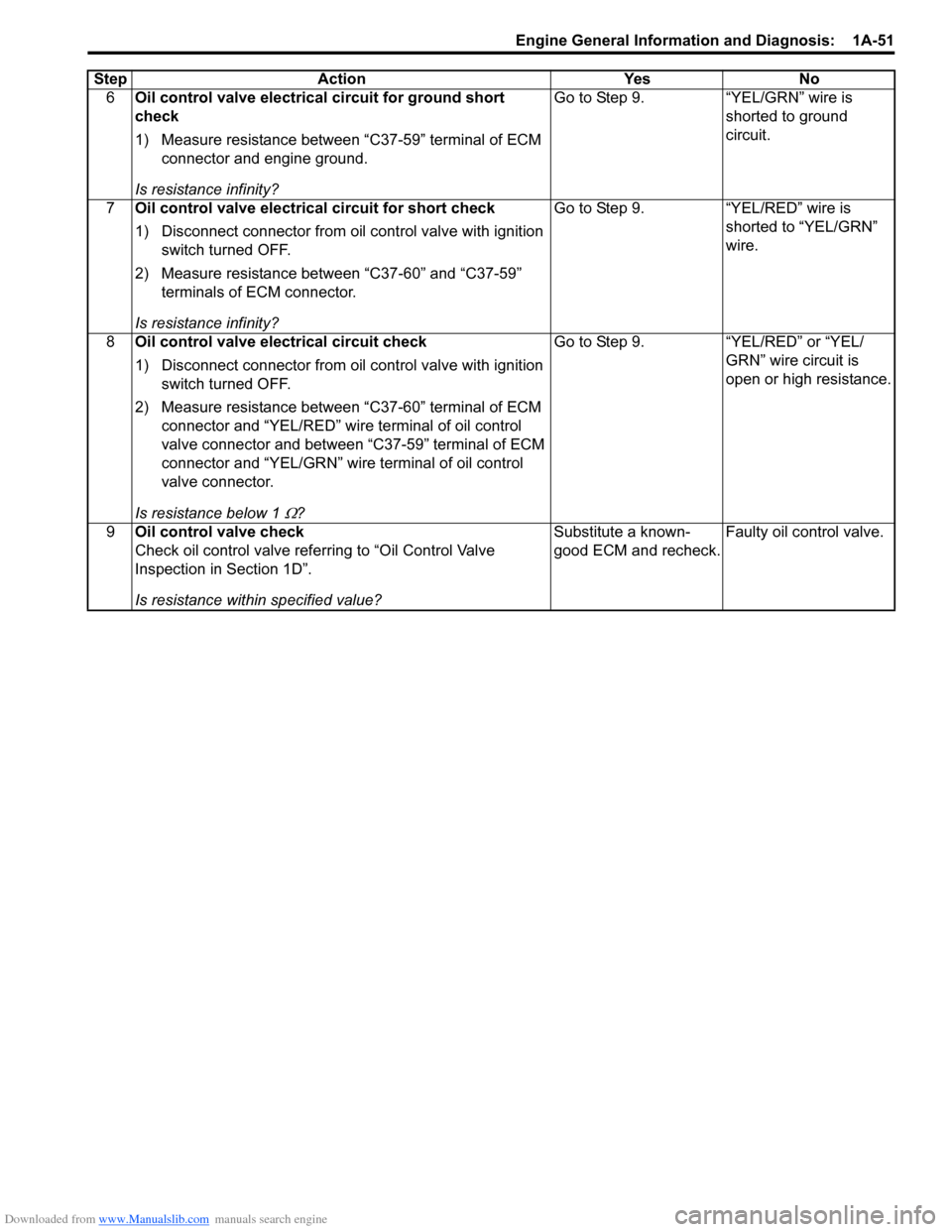
6Oil control valve electrical circuit for ground short
check
1) Measure resistance between “C37-59” terminal of ECM
connector and engine ground.
Is resistance infinity? Go to Step 9.
“YEL/GRN” wire is
shorted to ground
circuit.
7 Oil control valve electrical circuit for short check
1) Disconnect connector from oil control valve with ignition
switch turned OFF.
2) Measure resistance between “C37-60” and “C37-59” terminals of ECM connector.
Is resistance infinity? Go to Step 9.
“YEL/RED” wire is
shorted to “YEL/GRN”
wire.
8 Oil control valve electrical circuit check
1) Disconnect connector from oil control valve with ignition
switch turned OFF.
2) Measure resistance between “C37-60” terminal of ECM connector and “YEL/RED” wire terminal of oil control
valve connector and between “C37-59” terminal of ECM
connector and “YEL/GRN” wir e terminal of oil control
valve connector.
Is resistance below 1
Ω? Go to Step 9. “YEL/RED” or “YEL/
GRN” wire circuit is
open or high resistance.
9 Oil control valve check
Check oil control valve refe rring to “Oil Control Valve
Inspection in Section 1D”.
Is resistance within specified value? Substitute a known-
good ECM and recheck.
Faulty oil control valve.
Step Action Yes No
Page 105 of 1496
Downloaded from www.Manualslib.com manuals search engine Engine General Information and Diagnosis: 1A-55
StepAction YesNo
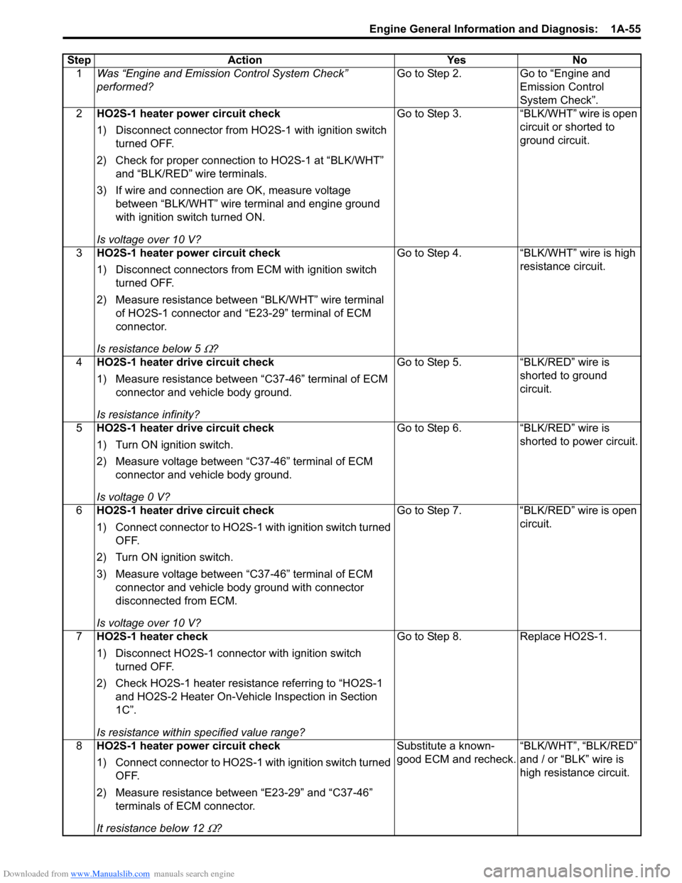
1 Was “Engine and Emission Control System Check”
performed? Go to Step 2.
Go to “Engine and
Emission Control
System Check”.
2 HO2S-1 heater power circuit check
1) Disconnect connector from HO 2S-1 with ignition switch
turned OFF.
2) Check for proper connection to HO2S-1 at “BLK/WHT” and “BLK/RED” wire terminals.
3) If wire and connection are OK, measure voltage between “BLK/WHT” wire terminal and engine ground
with ignition switch turned ON.
Is voltage over 10 V? Go to Step 3.
“BLK/WHT” wire is open
circuit or shorted to
ground circuit.
3 HO2S-1 heater power circuit check
1) Disconnect connectors from ECM with ignition switch
turned OFF.
2) Measure resistance between “BLK/WHT” wire terminal of HO2S-1 connector and “E 23-29” terminal of ECM
connector.
Is resistance below 5
Ω? Go to Step 4. “BLK/WHT” wire is high
resistance circuit.
4 HO2S-1 heater drive circuit check
1) Measure resistance between “C37-46” terminal of ECM
connector and vehicle body ground.
Is resistance infinity? Go to Step 5. “BLK/RED” wire is
shorted to ground
circuit.
5 HO2S-1 heater drive circuit check
1) Turn ON ignition switch.
2) Measure voltage between “C37-46” terminal of ECM
connector and vehicle body ground.
Is voltage 0 V? Go to Step 6. “BLK/RED” wire is
shorted to power circuit.
6 HO2S-1 heater drive circuit check
1) Connect connector to HO2S-1 with ignition switch turned
OFF.
2) Turn ON ignition switch.
3) Measure voltage between “C37-46” terminal of ECM connector and vehicle body ground with connector
disconnected from ECM.
Is voltage over 10 V? Go to Step 7. “BLK/RED” wire is open
circuit.
7 HO2S-1 heater check
1) Disconnect HO2S-1 connector with ignition switch
turned OFF.
2) Check HO2S-1 heater resistance referring to “HO2S-1 and HO2S-2 Heater On-Vehicle Inspection in Section
1C”.
Is resistance within specified value range? Go to Step 8. Replace HO2S-1.
8 HO2S-1 heater power circuit check
1) Connect connector to HO2S-1 with ignition switch turned
OFF.
2) Measure resistance between “E23-29” and “C37-46” terminals of ECM connector.
It resistance below 12
Ω? Substitute a known-
good ECM and recheck.
“BLK/WHT”, “BLK/RED”
and / or “BLK” wire is
high resistance circuit.
Page 107 of 1496
Downloaded from www.Manualslib.com manuals search engine Engine General Information and Diagnosis: 1A-57
StepAction YesNo
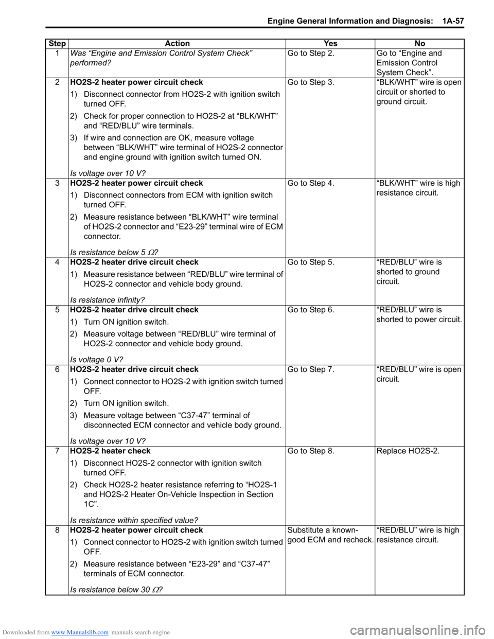
1 Was “Engine and Emission Control System Check”
performed? Go to Step 2.
Go to “Engine and
Emission Control
System Check”.
2 HO2S-2 heater power circuit check
1) Disconnect connector from HO 2S-2 with ignition switch
turned OFF.
2) Check for proper connection to HO2S-2 at “BLK/WHT” and “RED/BLU” wire terminals.
3) If wire and connection are OK, measure voltage between “BLK/WHT” wire terminal of HO2S-2 connector
and engine ground with ignition switch turned ON.
Is voltage over 10 V? Go to Step 3.
“BLK/WHT” wire is open
circuit or shorted to
ground circuit.
3 HO2S-2 heater power circuit check
1) Disconnect connectors from ECM with ignition switch
turned OFF.
2) Measure resistance between “BLK/WHT” wire terminal of HO2S-2 connector and “E23-29” terminal wire of ECM
connector.
Is resistance below 5
Ω? Go to Step 4. “BLK/WHT” wire is high
resistance circuit.
4 HO2S-2 heater drive circuit check
1) Measure resistance between “RED/BLU” wire terminal of
HO2S-2 connector and vehicle body ground.
Is resistance infinity? Go to Step 5. “RED/BLU” wire is
shorted to ground
circuit.
5 HO2S-2 heater drive circuit check
1) Turn ON ignition switch.
2) Measure voltage between “RED/BLU” wire terminal of
HO2S-2 connector and vehicle body ground.
Is voltage 0 V? Go to Step 6. “RED/BLU” wire is
shorted to power circuit.
6 HO2S-2 heater drive circuit check
1) Connect connector to HO2S-2 with ignition switch turned
OFF.
2) Turn ON ignition switch.
3) Measure voltage between “C37-47” terminal of disconnected ECM connector and vehicle body ground.
Is voltage over 10 V? Go to Step 7.
“RED/BLU” wire is open
circuit.
7 HO2S-2 heater check
1) Disconnect HO2S-2 connector with ignition switch
turned OFF.
2) Check HO2S-2 heater resistance referring to “HO2S-1 and HO2S-2 Heater On-Vehicle Inspection in Section
1C”.
Is resistance within specified value? Go to Step 8.
Replace HO2S-2.
8 HO2S-2 heater power circuit check
1) Connect connector to HO2S-2 with ignition switch turned
OFF.
2) Measure resistance between “E23-29” and “C37-47” terminals of ECM connector.
Is resistance below 30
Ω? Substitute a known-
good ECM and recheck.
“RED/BLU” wire is high
resistance circuit.
Page 110 of 1496
Downloaded from www.Manualslib.com manuals search engine 1A-60 Engine General Information and Diagnosis:
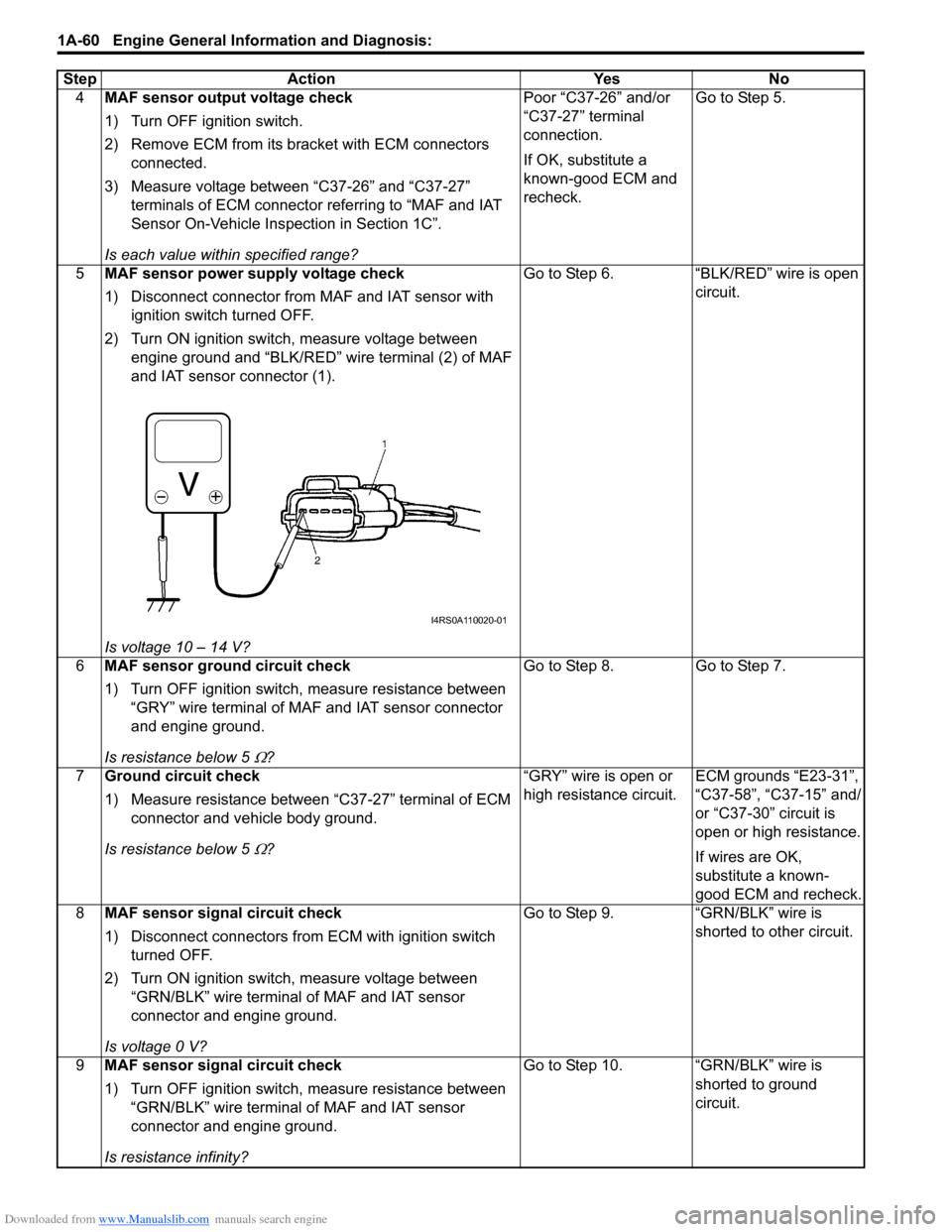
4MAF sensor output voltage check
1) Turn OFF ignition switch.
2) Remove ECM from its br acket with ECM connectors
connected.
3) Measure voltage between “C37-26” and “C37-27” terminals of ECM connector referring to “MAF and IAT
Sensor On-Vehicle Inspection in Section 1C”.
Is each value within specified range? Poor “C37-26” and/or
“C37-27” terminal
connection.
If OK, substitute a
known-good ECM and
recheck.
Go to Step 5.
5 MAF sensor power supply voltage check
1) Disconnect connector from MAF and IAT sensor with
ignition switch turned OFF.
2) Turn ON ignition switch, measure voltage between engine ground and “BLK/RED” wire terminal (2) of MAF
and IAT sensor connector (1).
Is voltage 10 – 14 V? Go to Step 6. “BLK/RED” wire is open
circuit.
6 MAF sensor ground circuit check
1) Turn OFF ignition switch, measure resistance between
“GRY” wire terminal of MAF and IAT sensor connector
and engine ground.
Is resistance below 5
Ω? Go to Step 8.
Go to Step 7.
7 Ground circuit check
1) Measure resistance between “C37-27” terminal of ECM
connector and vehicle body ground.
Is resistance below 5
Ω? “GRY” wire is open or
high resistance circuit.
ECM grounds “E23-31”,
“C37-58”, “C37-15” and/
or “C37-30” circuit is
open or high resistance.
If wires are OK,
substitute a known-
good ECM and recheck.
8 MAF sensor signal circuit check
1) Disconnect connectors from ECM with ignition switch
turned OFF.
2) Turn ON ignition switch, measure voltage between “GRN/BLK” wire terminal of MAF and IAT sensor
connector and engine ground.
Is voltage 0 V? Go to Step 9. “GRN/BLK” wire is
shorted to other circuit.
9 MAF sensor signal circuit check
1) Turn OFF ignition switch, measure resistance between
“GRN/BLK” wire terminal of MAF and IAT sensor
connector and engine ground.
Is resistance infinity? Go to Step 10. “GRN/BLK” wire is
shorted to ground
circuit.
Step Action Yes No
I4RS0A110020-01
Page 112 of 1496
Downloaded from www.Manualslib.com manuals search engine 1A-62 Engine General Information and Diagnosis:
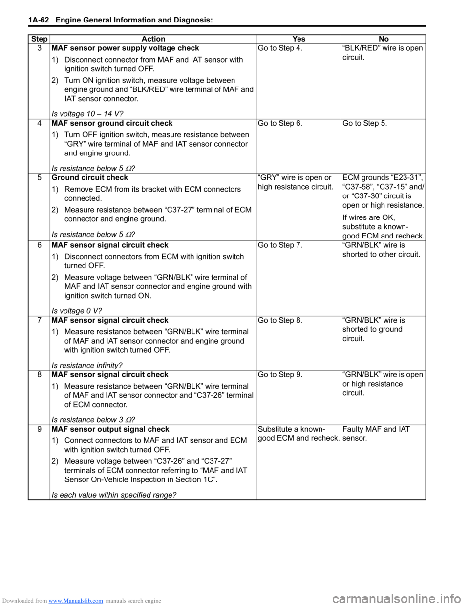
3MAF sensor power supply voltage check
1) Disconnect connector from MAF and IAT sensor with
ignition switch turned OFF.
2) Turn ON ignition switch, measure voltage between engine ground and “BLK/RED” wire terminal of MAF and
IAT sensor connector.
Is voltage 10 – 14 V? Go to Step 4. “BLK/RED” wire is open
circuit.
4 MAF sensor ground circuit check
1) Turn OFF ignition switch, measure resistance between
“GRY” wire terminal of MAF and IAT sensor connector
and engine ground.
Is resistance below 5
Ω? Go to Step 6.
Go to Step 5.
5 Ground circuit check
1) Remove ECM from its br acket with ECM connectors
connected.
2) Measure resistance between “C37-27” terminal of ECM connector and engine ground.
Is resistance below 5
Ω? “GRY” wire is open or
high resistance circuit.
ECM grounds “E23-31”,
“C37-58”, “C37-15” and/
or “C37-30” circuit is
open or high resistance.
If wires are OK,
substitute a known-
good ECM and recheck.
6 MAF sensor signal circuit check
1) Disconnect connectors from ECM with ignition switch
turned OFF.
2) Measure voltage between “GRN/BLK” wire terminal of MAF and IAT sensor connector and engine ground with
ignition switch turned ON.
Is voltage 0 V? Go to Step 7. “GRN/BLK” wire is
shorted to other circuit.
7 MAF sensor signal circuit check
1) Measure resistance between “GRN/BLK” wire terminal
of MAF and IAT sensor connector and engine ground
with ignition swit ch turned OFF.
Is resistance infinity? Go to Step 8.
“GRN/BLK” wire is
shorted to ground
circuit.
8 MAF sensor signal circuit check
1) Measure resistance between “GRN/BLK” wire terminal
of MAF and IAT sensor connector and “C37-26” terminal
of ECM connector.
Is resistance below 3
Ω? Go to Step 9.
“GRN/BLK” wire is open
or high resistance
circuit.
9 MAF sensor output signal check
1) Connect connectors to MAF and IAT sensor and ECM
with ignition swit ch turned OFF.
2) Measure voltage between “C37-26” and “C37-27” terminals of ECM connector referring to “MAF and IAT
Sensor On-Vehicle Inspection in Section 1C”.
Is each value within specified range? Substitute a known-
good ECM and recheck.
Faulty MAF and IAT
sensor.
Step
Action YesNo