2006 SUZUKI SWIFT engine cover
[x] Cancel search: engine coverPage 1152 of 1496
Downloaded from www.Manualslib.com manuals search engine 8B-114 Air Bag System:
Deployment / Activation Outside of Vehicle
When you intend to return the vehicle to service, deploy
the air bag (inflator) module(s) or activate seat belt
pretensioner(s) outside of the vehicle.1) Turn ignition switch to LOCK position and remove key.
2) Wear safety glasses during this deployment / activation procedure.
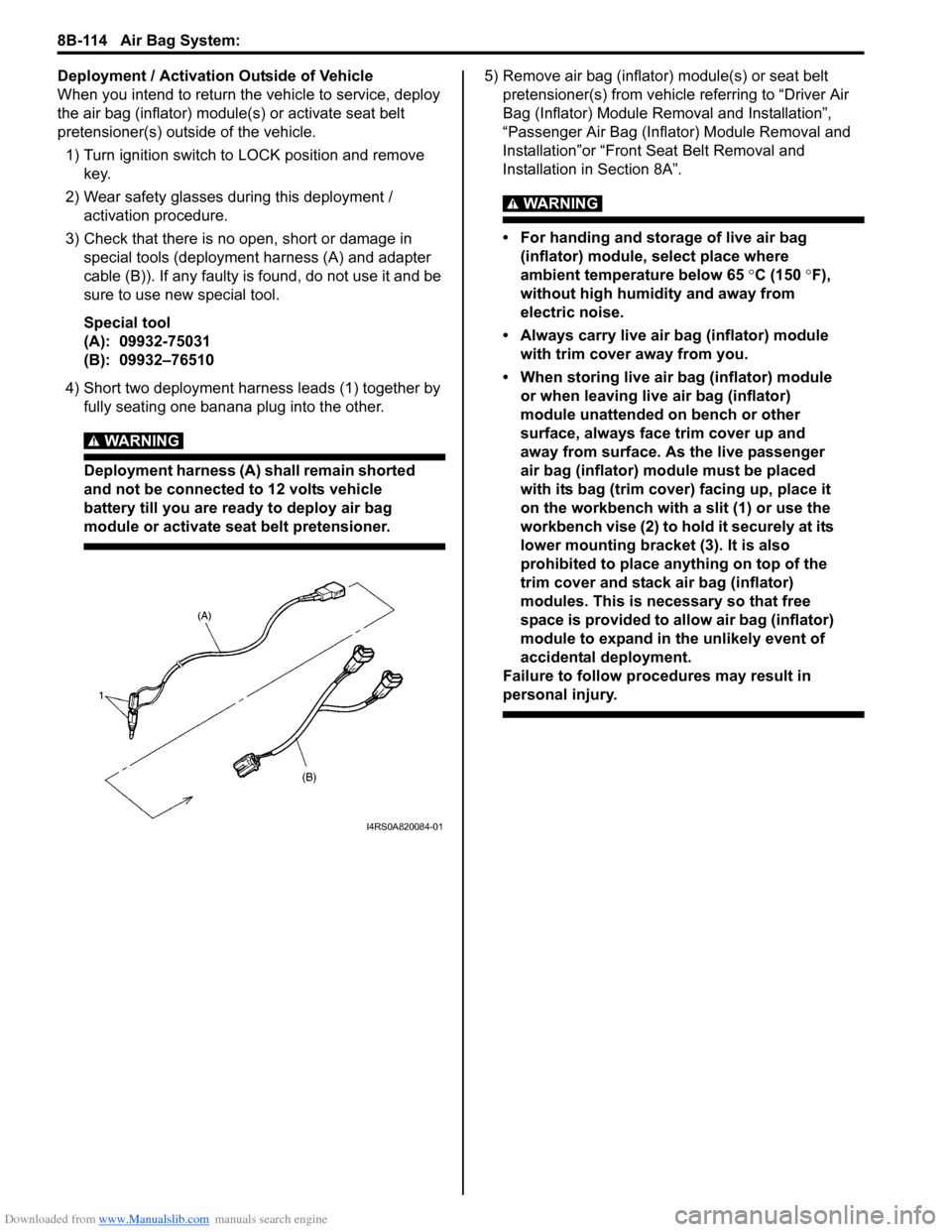
3) Check that there is no open, short or damage in special tools (deployment harness (A) and adapter
cable (B)). If any faulty is found, do not use it and be
sure to use new special tool.
Special tool
(A): 09932-75031
(B): 09932–76510
4) Short two deployment harness leads (1) together by fully seating one banana plug into the other.
WARNING!
Deployment harness (A) shall remain shorted
and not be connected to 12 volts vehicle
battery till you are ready to deploy air bag
module or activate seat belt pretensioner.
5) Remove air bag (inflator) module(s) or seat belt pretensioner(s) from vehicle referring to “Driver Air
Bag (Inflator) Module Re moval and Installation”,
“Passenger Air Bag (Inflator) Module Removal and
Installation”or “Front Seat Belt Removal and
Installation in Section 8A”.
WARNING!
• For handing and storage of live air bag (inflator) module, select place where
ambient temperature below 65 °C (150 °F),
without high humidity and away from
electric noise.
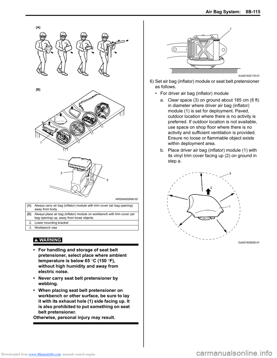
• Always carry live air bag (inflator) module with trim cover away from you.
• When storing live air bag (inflator) module or when leaving live air bag (inflator)
module unattended on bench or other
surface, always face trim cover up and
away from surface. As the live passenger
air bag (inflator) module must be placed
with its bag (trim cover) facing up, place it
on the workbench with a slit (1) or use the
workbench vise (2) to hold it securely at its
lower mounting bracket (3). It is also
prohibited to place anything on top of the
trim cover and stack air bag (inflator)
modules. This is necessary so that free
space is provided to allow air bag (inflator)
module to expand in the unlikely event of
accidental deployment.
Failure to follow procedures may result in
personal injury.
I4RS0A820084-01
Page 1153 of 1496
Downloaded from www.Manualslib.com manuals search engine Air Bag System: 8B-115
WARNING!
• For handling and storage of seat belt pretensioner, select place where ambient
temperature is below 65 °C (150 °F),
without high humidity and away from
electric noise.
• Never carry seat belt pretensioner by webbing.
• When placing seat belt pretensioner on workbench or other surface, be sure to lay
it with its exhaust hole (1) side facing up. It
is also prohibited to put something on seat
belt pretensioner.
Otherwise, personal injury may result.
6) Set air bag (inflator) module or seat belt pretensioner
as follows.
• For driver air bag (inflator) module
a. Clear space (3) on ground about 185 cm (6 ft) in diameter where driver air bag (inflator)
module (1) is set for deployment. Paved,
outdoor location where there is no activity is
preferred. If outdoor location is not available,
use space on shop floor where there is no
activity and sufficient ventilation is provided.
Ensure no loose or flammable object exists
within deployment area.
b. Place driver air bag (inflator) module (1) with its vinyl trim cover facing up (2) on ground in
step a.
[A]: Always carry air bag (inflator) module with trim cover (air bag opening) away from body.
[B]: Always place air bag (inflator) module on workbench with trim cover (air bag opening) up, away from loose objects.
2. Lower mounting bracket
3. Workbench vise
1
2
3
[A]
[B]
I4RS0A820086-02
1
I4JA01822118-01
I3JA01820036-01
Page 1156 of 1496
Downloaded from www.Manualslib.com manuals search engine 8B-118 Air Bag System:
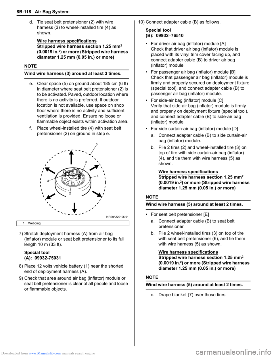
d. Tie seat belt pretensioner (2) with wire harness (3) to wheel-installed tire (4) as
shown.
Wire harness specifications
Stripped wire harness section 1.25 mm2
(0.0019 in.2) or more (Stripped wire harness
diameter 1.25 mm (0.05 in.) or more)
NOTE
Wind wire harness (3) around at least 3 times.
e. Clear space (5) on ground about 185 cm (6 ft) in diameter where seat belt pretensioner (2) is
to be activated. Paved, outdoor location where
there is no activity is preferred. If outdoor
location is not available, use space on shop
floor where there is no activity and sufficient
ventilation is provided. Ensure no loose or
flammable object exists within activation area.
f. Place wheel-installed tire (4) with seat belt pretensioner (2) on ground in step e.
7) Stretch deployment harness (A) from air bag (inflator) module or seat belt pretensioner to its full
length 10 m (33 ft).
Special tool
(A): 09932-75031
8) Place 12 volts vehicle battery (1) near the shorted end of deployment harness (A).
9) Check that area around air bag (inflator) module or seat belt pretensioner is clear of all people and loose
or flammable objects. 10) Connect adapter cable (B) as follows.
Special tool
(B): 09932–76510
• For driver air bag (inflator) module [A]Check that driver air bag (inflator) module is
placed with its vinyl trim cover facing up, and
connect adapter cable (B) to driver air bag
(inflator) module.
• For passenger air bag (inflator) module [B] Check that passenger air bag (inflator) module is
firmly and properly secured on deployment fixture
(special tool), and connect adapter cable (B) to
passenger air bag (inflator) module.
• For side-air bag (inflator) module [C] Verify that side-air bag (inflator) module is firmly
and properly on deployment fixture (special tool),
and connect adapter cable (B) to side-air bag
(inflator) module.
• For side curtain-air bag (inflator) module [D] a. Connect adapter cable (B) to side curtain-air bag (inflator) module.
b. Pile 2 tires (2) and wheel-installed tire (3) on top of tire with side curtain-air bag (inflator)
(4), and tie them with wire harness (5) as
shown.
Wire harness specifications
Stripped wire harness section 1.25 mm2
(0.0019 in.2) or more (Stripped wire harness
diameter 1.25 mm (0.05 in.) or more)
NOTE
Wind wire harness (5) around at least 2 times.
• For seat belt pretensioner [E]
a. Connect adapter cable (B) to seat belt pretensioner.
b. Pile 2 wheel-installed tires (3) on top of tire with seat belt pretensioner (6), and tie them
with wire harness (5) as shown.
Wire harness specifications
Stripped wire harness section 1.25 mm2
(0.0019 in.2) or more (Stripped wire harness
diameter 1.25 mm (0.05 in.) or more)
NOTE
Wind wire harness (5) around at least 2 times.
c. Drape blanket (7) over those tires.
1. Webbing
4
3
3 2 5
I4RS0A820105-01
Page 1161 of 1496
Downloaded from www.Manualslib.com manuals search engine Air Bag System: 8B-123
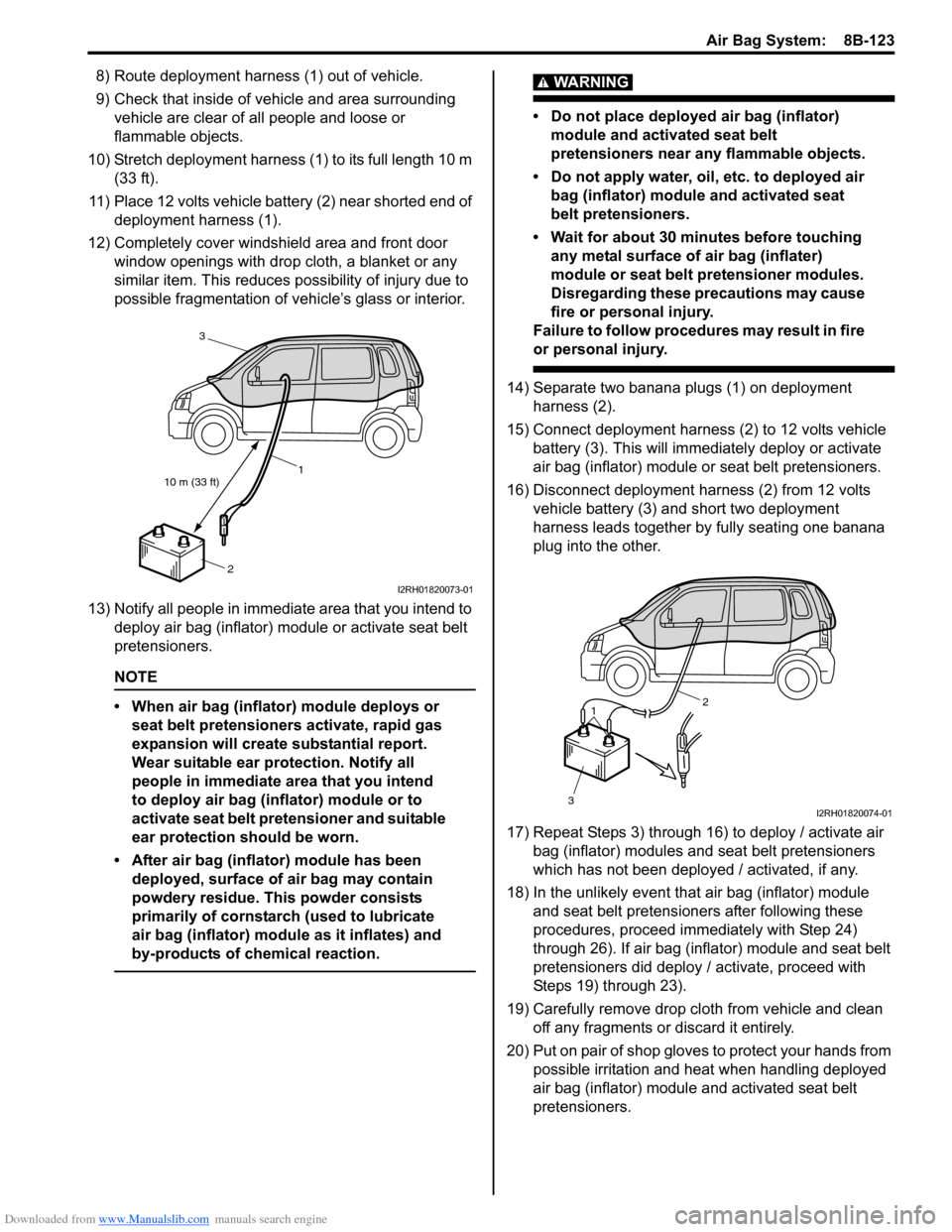
8) Route deployment harness (1) out of vehicle.
9) Check that inside of vehicle and area surrounding vehicle are clear of all people and loose or
flammable objects.
10) Stretch deployment harness (1) to its full length 10 m (33 ft).
11) Place 12 volts vehicle battery (2) near shorted end of deployment harness (1).
12) Completely cover windshield area and front door window openings with drop cloth, a blanket or any
similar item. This reduces possibility of injury due to
possible fragmentation of vehicle’s glass or interior.
13) Notify all people in immediate area that you intend to deploy air bag (inflator) module or activate seat belt
pretensioners.
NOTE
• When air bag (inflator) module deploys or seat belt pretensioners activate, rapid gas
expansion will create substantial report.
Wear suitable ear protection. Notify all
people in immediate area that you intend
to deploy air bag (inflator) module or to
activate seat belt pretensioner and suitable
ear protection should be worn.
• After air bag (inflator) module has been deployed, surface of air bag may contain
powdery residue. This powder consists
primarily of cornstarch (used to lubricate
air bag (inflator) module as it inflates) and
by-products of chemical reaction.
WARNING!
• Do not place deployed air bag (inflator) module and activated seat belt
pretensioners near any flammable objects.
• Do not apply water, oil, etc. to deployed air bag (inflator) module and activated seat
belt pretensioners.
• Wait for about 30 minutes before touching any metal surface of air bag (inflater)
module or seat belt pretensioner modules.
Disregarding these precautions may cause
fire or personal injury.
Failure to follow procedures may result in fire
or personal injury.
14) Separate two banana plugs (1) on deployment harness (2).
15) Connect deployment harness (2) to 12 volts vehicle battery (3). This will immedi ately deploy or activate
air bag (inflator) module or seat belt pretensioners.
16) Disconnect deployment harness (2) from 12 volts vehicle battery (3) and short two deployment
harness leads together by fully seating one banana
plug into the other.
17) Repeat Steps 3) through 16) to deploy / activate air bag (inflator) modules and seat belt pretensioners
which has not been deployed / activated, if any.
18) In the unlikely event that air bag (inflator) module and seat belt pretensioners after following these
procedures, proceed immediately with Step 24)
through 26). If air bag (inflator) module and seat belt
pretensioners did deploy / activate, proceed with
Steps 19) through 23).
19) Carefully remove drop cloth from vehicle and clean off any fragments or discard it entirely.
20) Put on pair of shop gloves to protect your hands from
possible irritation and heat when handling deployed
air bag (inflator) module and activated seat belt
pretensioners.
10 m (33 ft) 1
2
3
I2RH01820073-01
1
3 2
I2RH01820074-01
Page 1205 of 1496
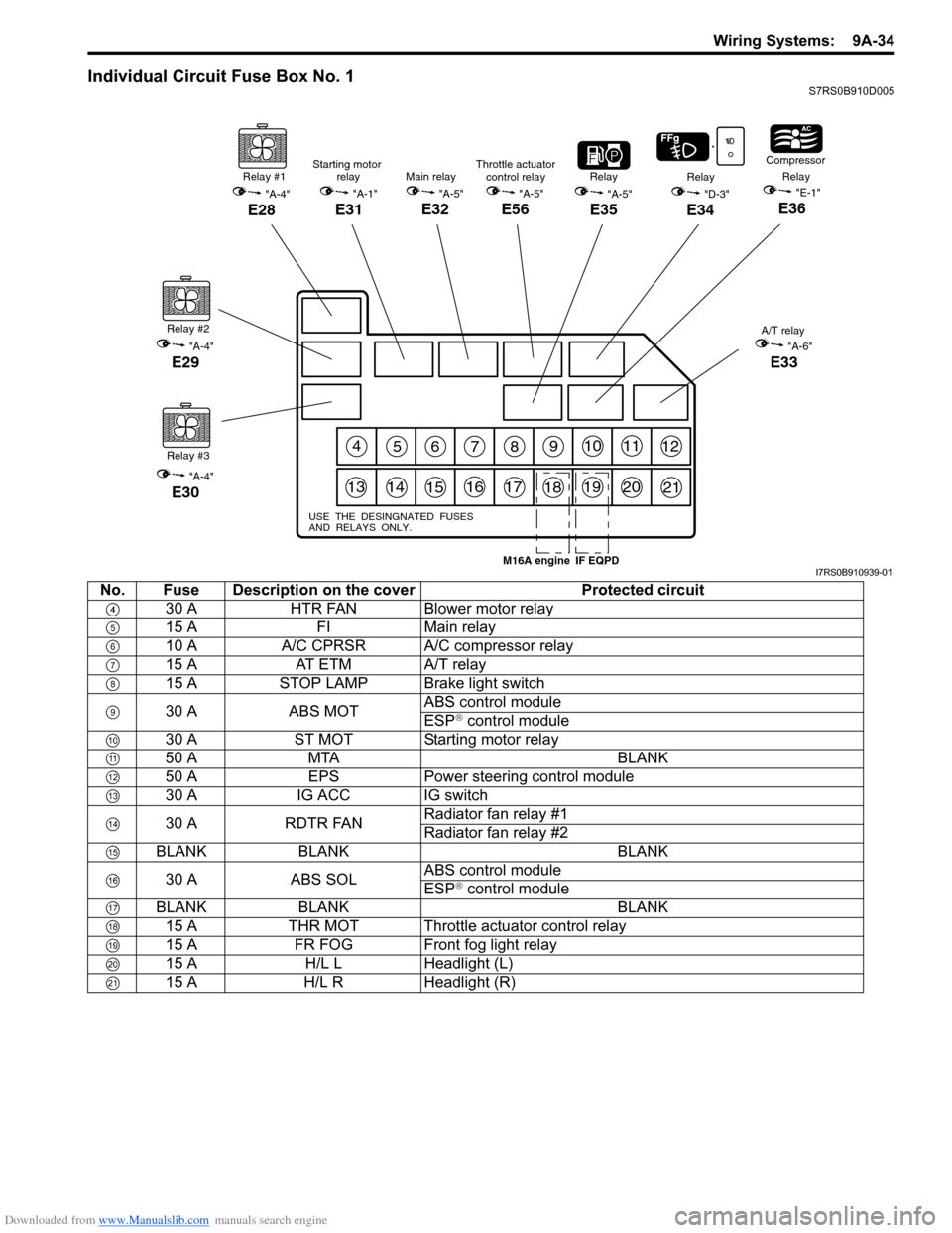
Downloaded from www.Manualslib.com manuals search engine Wiring Systems: 9A-34
Individual Circuit Fuse Box No. 1S7RS0B910D005
456789101112
131415161718192021
USE THE DESINGNATED FUSES
AND RELAYS ONLY.
Relay #1
"A-4"
E28
Relay #2
"A-4"
E29
Relay #3
"A-4"
E30
"A-5"
E35
RelayRelay
"D-3"
E34
Compressor
Relay"E-1"
E36
A/T relay
"A-6"
E33
Main relay
"A-5"
E32
Starting motor relay
"A-1"
E31
Throttle actuatorcontrol relay
"A-5"
E56
IF EQPDM16A engineI7RS0B910939-01
No. Fuse Description on the cover Protected circuit
30 A HTR FAN Blower motor relay
15 A FIMain relay
10 A A/C CPRSR A/C compressor relay
15 A AT ETM A/T relay
15 A STOP LAMP Brake light switch
30 A ABS MOT ABS control module
ESP
® control module
30 A ST MOT Starting motor relay
50 A MTA BLANK
50 A EPS Power steering control module
30 A IG ACC IG switch
30 A RDTR FAN Radiator fan relay #1
Radiator fan relay #2
BLANK BLANK BLANK
30 A ABS SOL ABS control module
ESP
® control module
BLANK BLANK BLANK 15 A THR MOT Throttle actuator control relay
15 A FR FOG Front fog light relay
15 A H/L L Headlight (L)
15 A H/L R Headlight (R)
Page 1206 of 1496
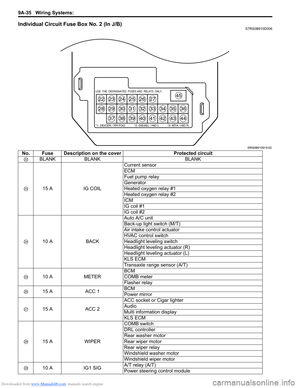
Downloaded from www.Manualslib.com manuals search engine 9A-35 Wiring Systems:
Individual Circuit Fuse Box No. 2 (In J/B)S7RS0B910D006
22
28
23
29
37
24
30
38
25
31
39
26
32
40
27
33
41
34
42
35
43
36
44
45USE THE DESINGNATED FUSES AND RELAYS ONLY.
*1: DEICER / RR FOG *2: DIESEL / HID L *3: MTA / HID R
I5RS0B910919-02
No. Fuse Description on the coverProtected circuit
BLANK BLANK BLANK
15 A IG COILCurrent sensor
ECM
Fuel pump relay
Generator
Heated oxygen relay #1
Heated oxygen relay #2
ICM
IG coil #1
IG coil #2
10 A BACKAuto A/C unit
Back-up light switch (M/T)
Air intake control actuator
HVAC control switch
Headlight leveling switch
Headlight leveling actuator (R)
Headlight leveling actuator (L)
KLS ECM
Transaxle range sensor (A/T)
10 A METERBCM
COMB meter
Flasher relay
15 A ACC 1BCM
Power mirror
15 A ACC 2ACC socket or Cigar lighter
Audio
Multi information display
KLS ECM
15 A WIPERCOMB switch
DRL controller
Rear washer motor
Rear wiper motor
Rear wiper relay
Windshield washer motor
Windshield wiper motor
10 A IG1 SIGA/T relay (A/T)
Power steering control module
Page 1207 of 1496
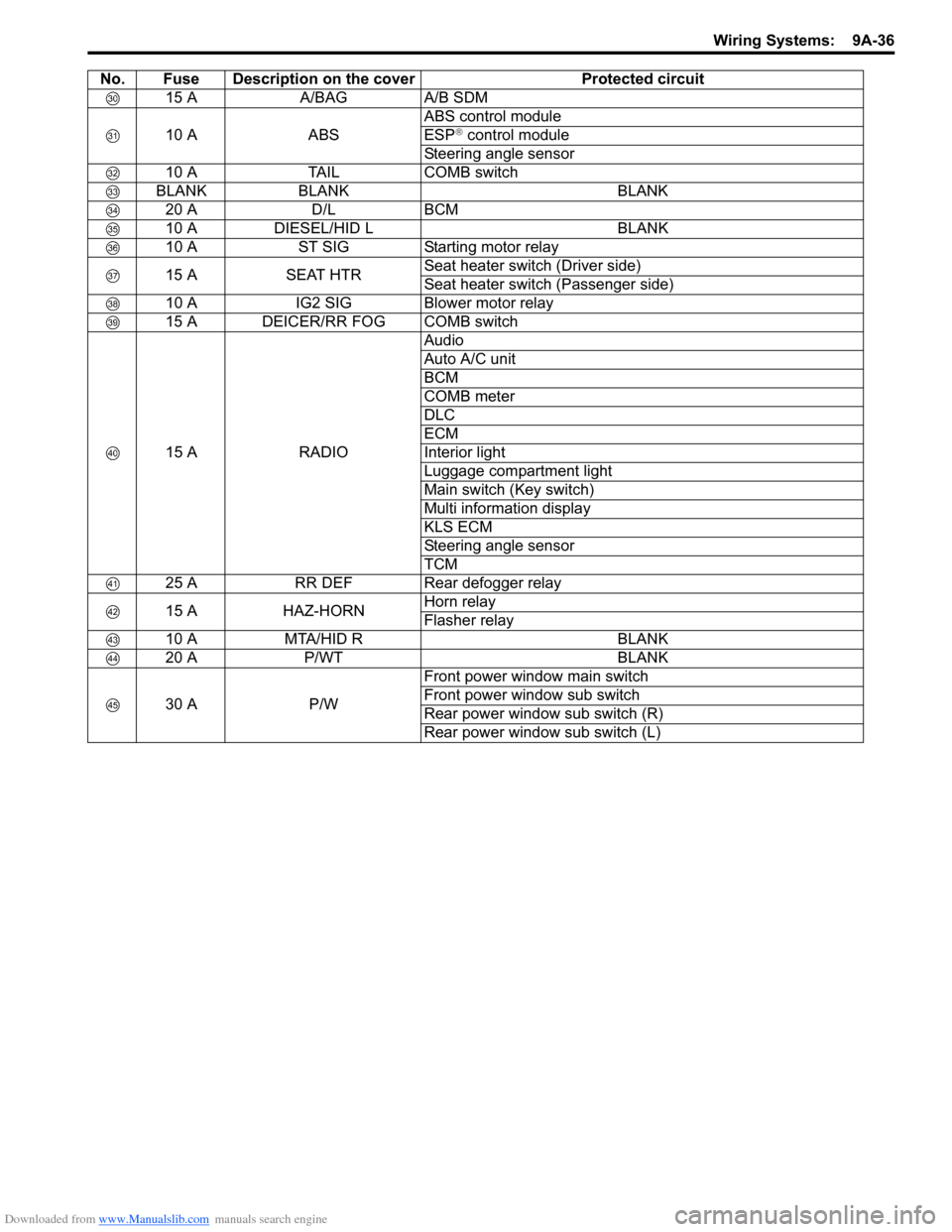
Downloaded from www.Manualslib.com manuals search engine Wiring Systems: 9A-36
15 AA/BAG A/B SDM
10 A ABSABS control module
ESP
® control module
Steering angle sensor
10 A TAIL COMB switch
BLANK BLANK BLANK 20 A D/L BCM
10 A DIESEL/HID L BLANK
10 A ST SIG Starting motor relay
15 A SEAT HTR Seat heater switch (Driver side)
Seat heater switch (Passenger side)
10 A IG2 SIG Blower motor relay
15 A DEICER/RR FOG COMB switch
15 A RADIO Audio
Auto A/C unit
BCM
COMB meter
DLC
ECM
Interior light
Luggage compartment light
Main switch (Key switch)
Multi information display
KLS ECM
Steering angle sensor
TCM
25 A RR DEF Rear defogger relay
15 A HAZ-HORN Horn relay
Flasher relay
10 A MTA/HID R BLANK
20 A P/WT BLANK
30 A P/W Front power window main switch
Front power window sub switch
Rear power window sub switch (R)
Rear power window sub switch (L)
No. Fuse Description on the cover Protected circuit
Page 1283 of 1496
Downloaded from www.Manualslib.com manuals search engine Lighting Systems: 9B-1
Body, Cab and Accessories
Lighting Systems
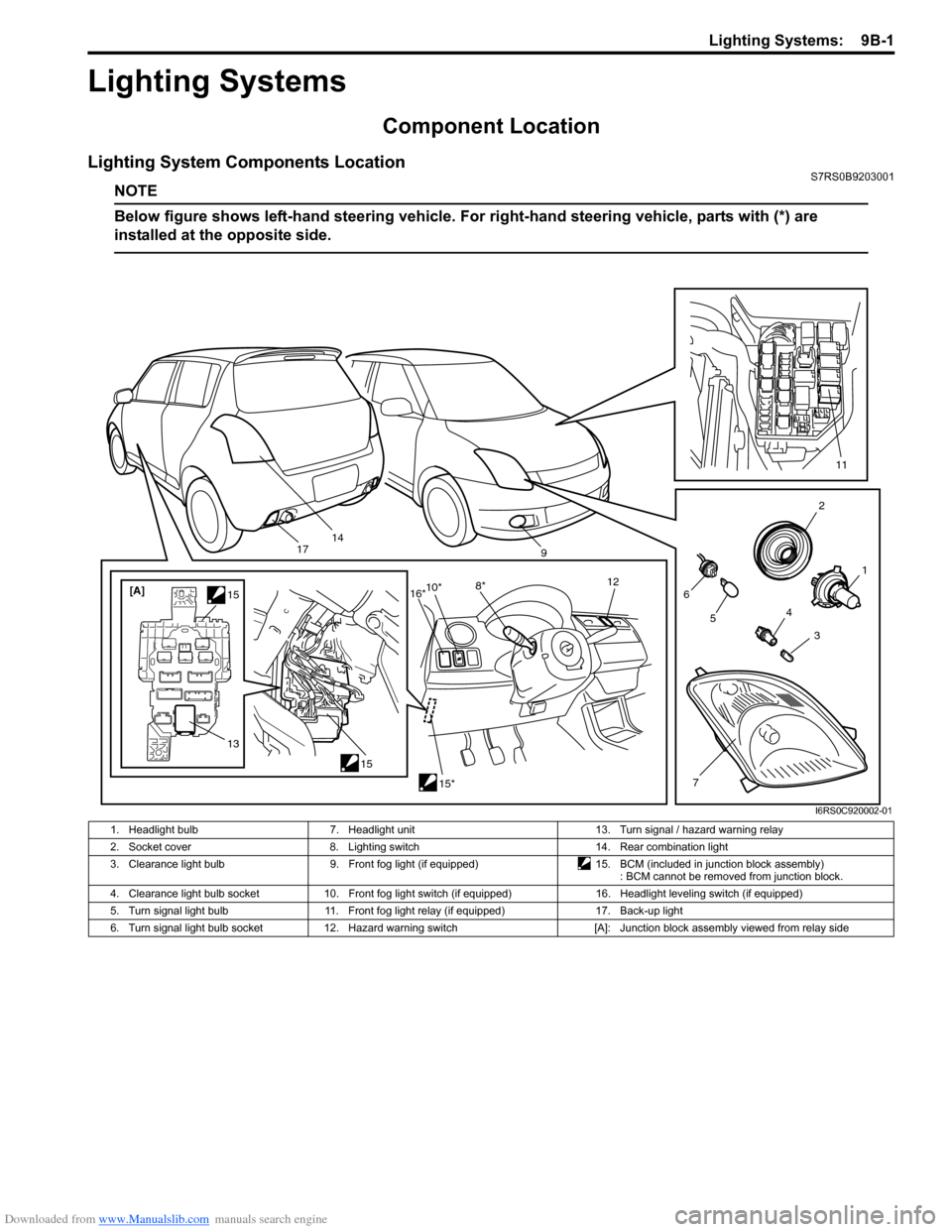
Component Location
Lighting System Components LocationS7RS0B9203001
NOTE
Below figure shows left-hand steering vehicle. For right-hand steering vehicle, parts with (*) are
installed at the opposite side.
2
1
3
4
6
14
5
7
11
9
15
[A]
1515*
10*
8* 12
13
16*
17
I6RS0C920002-01
1. Headlight bulb 7. Headlight unit 13. Turn signal / hazard warning relay
2. Socket cover 8. Lighting switch 14. Rear combination light
3. Clearance light bulb 9. Front fog light (if equipped)15. BCM (included in junction block assembly)
: BCM cannot be removed from junction block.
4. Clearance light bulb socket 10. Front fog light switch (if equipped) 16. Headlight leveling switch (if equipped)
5. Turn signal light bulb 11. Front fog light relay (if equipped) 17. Back-up light
6. Turn signal light bulb socket 12. Hazard warning switch [A]: Junction block assembly viewed from relay side