2006 SUZUKI SWIFT Time
[x] Cancel search: TimePage 958 of 1496

Downloaded from www.Manualslib.com manuals search engine 7B-10 Air Conditioning System: Manual Type
Abnormal Noise from Tension Pulley
Abnormal Noise from A/C Evaporator
Abnormal Noise from Blower Motor
A/C System Performance InspectionS7RS0B7214003
1) Confirm that vehicle and environmental conditions are as follows.
• Vehicle is put indoors.
• Ambient temperature is within 25 – 35 °C (77 – 95
° F).
• Relative humidity is within 30 – 70%.
• There is no wind indoors.
• HVAC unit is normal.
• Blower motor is normal.
• There is no air leakage from air ducts.
• Condenser fins are clean.
• Air filter in HVAC unit is not clogged with dirt and
dust.
• Battery voltage is about 12 V.
• Radiator cooling fan operates normally.
2) Make sure that high pressure valve (1) and low pressure valve (2) of manifold gauge are firmly
closed.
3) Connect high pressure charging hose (3) to high pressure service valve (5) on vehicle and low
pressure charging hose (4) to low pressure service
valve (6).
4) Bleed the air in charging hoses (3) and (4) by loosening their nuts respectively utilizing the
refrigerant pressure. When a hissing sound is heard,
immediately tighten nut.
CAUTION!
Do not connect high and low pressure
charging hoses in reverse.
Condition Possible cause Correction / Reference Item
Clattering noise is heard
from pulley Worn or damaged bearing
Replace tension pulley.
Pulley cranks upon
contact Cracked or loose bracket
Replace or retighten bracket.
ConditionPossible cause Correction / Reference Item
Whistling sound is heard
from A/C evaporator Depending on the combination of the
interior / exterior temperatures, engine
rpm and refrigerant pressure, the
refrigerant flowing out of the expansion
valve may, under certain conditions,
make a whistling sound At times, slightly decrea
sing refrigerant volume
may stop this noise.
Inspect expansion valve and replace if faulty.
Condition Possible cause Correction / Reference Item
Blower motor emits a
chirping sound in
proportion to its speed of
rotation Worn or damaged motor brushes or
commutator
Replace blower motor.
Fluttering noise or large
droning noise is heard
from blower motor Leaves or other debris introduced from
fresh air inlet to blower motor
Remove debris and make sure that the screen
at fresh air inlet is intact.
53
2
1
4 6
I4RS0A720006-01
Page 962 of 1496
Downloaded from www.Manualslib.com manuals search engine 7B-14 Air Conditioning System: Manual Type
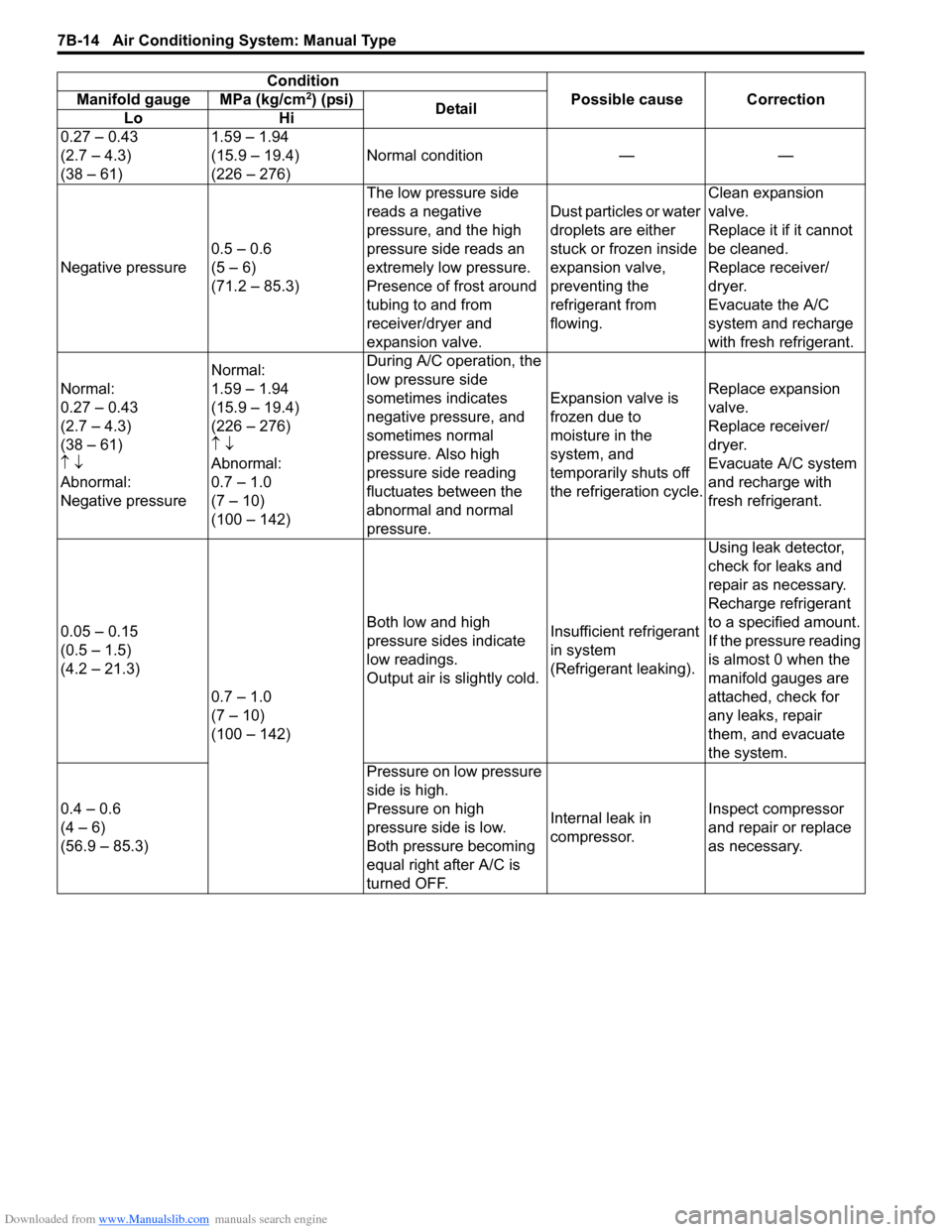
ConditionPossible cause Correction
Manifold gauge MPa (kg/cm2) (psi)
Detail
Lo Hi
0.27 – 0.43
(2.7 – 4.3)
(38 – 61) 1.59 – 1.94
(15.9 – 19.4)
(226 – 276)
Normal condition — —
Negative pressure 0.5 – 0.6
(5 – 6)
(71.2 – 85.3) The low pressure side
reads a negative
pressure, and the high
pressure side reads an
extremely low pressure.
Presence of frost around
tubing to and from
receiver/dryer and
expansion valve. Dust particles or water
droplets are either
stuck or frozen inside
expansion valve,
preventing the
refrigerant from
flowing.Clean expansion
valve.
Replace it if it cannot
be cleaned.
Replace receiver/
dryer.
Evacuate the A/C
system and recharge
with fresh refrigerant.
Normal:
0.27 – 0.43
(2.7 – 4.3)
(38 – 61)
↑ ↓
Abnormal:
Negative pressure Normal:
1.59 – 1.94
(15.9 – 19.4)
(226 – 276)
↑
↓
Abnormal:
0.7 – 1.0
(7 – 10)
(100 – 142) During A/C operation, the
low pressure side
sometimes indicates
negative pressure, and
sometimes normal
pressure. Also high
pressure side reading
fluctuates between the
abnormal and normal
pressure.
Expansion valve is
frozen due to
moisture in the
system, and
temporarily shuts off
the refrigeration cycle.
Replace expansion
valve.
Replace receiver/
dryer.
Evacuate A/C system
and recharge with
fresh refrigerant.
0.05 – 0.15
(0.5 – 1.5)
(4.2 – 21.3) 0.7 – 1.0
(7 – 10)
(100 – 142) Both low and high
pressure sides indicate
low readings.
Output air is slightly cold.
Insufficient refrigerant
in system
(Refrigerant leaking).Using leak detector,
check for leaks and
repair as necessary.
Recharge refrigerant
to a specified amount.
If the pressure reading
is almost 0 when the
manifold gauges are
attached, check for
any leaks, repair
them, and evacuate
the system.
0.4 – 0.6
(4 – 6)
(56.9 – 85.3) Pressure on low pressure
side is high.
Pressure on high
pressure side is low.
Both pressure becoming
equal right after A/C is
turned OFF.
Internal leak in
compressor.
Inspect compressor
and repair or replace
as necessary.
Page 967 of 1496
Downloaded from www.Manualslib.com manuals search engine Air Conditioning System: Manual Type 7B-19
Charge
CAUTION!
• Because the sight glass is not used for this A/C system, do not perform an additional
charge to the A/C system. To charge the
proper amount of refrigerant, recover and
evacuate the A/C system first. And then,
charge the proper amount of refrigerant
into the A/C system.
• Always charge refrigerant through low pressure side of A/C system after the initial
charge is performed from the high
pressure side with the engine stopped.
• Never charge refrigerant through high pressure side of A/C system with engine
running.
• Do not charge refrigerant while compressor is hot.
• When installing tap valve to refrigerant container to make a hole there through,
carefully follow dire ctions given by
manufacturer.
• A pressure gauge should always be used before and during refrigerant charge.
• The refrigerant container should be emptied of refrigerant when discarding it.
• The refrigerant container should not be heated up to 40 °C (104 °F) or over.
• Refrigerant container should not be reversed in direction during refrigerant
charge. Reversing in direction causes
liquid refrigerant to enter compressor,
causing troubles, such as compression of
liquid refrigerant and the like.
NOTE
The air conditioning system contains HFC-
134a (R-134a).
Described here is a method to charge the air
conditioning system with refrigerant from the
refrigerant service container.
When charging refrigerant recovered by
using the refrigerant and recycling
equipment (when recycling refrigerant),
follow the procedure described in the
equipment manufacturer’s instruction
manual.
Charge proper amount of refrigerant accurately in
accordance with the following procedure.
Specified amount of refrigerant
370 ± 20 g (13.0 ± 0.7 oz)
The initial charge of the A/C system is performed
through the high pressure side with the engine stopped.
And next, this method must be followed by charging from
the low pressure side with the engine running.
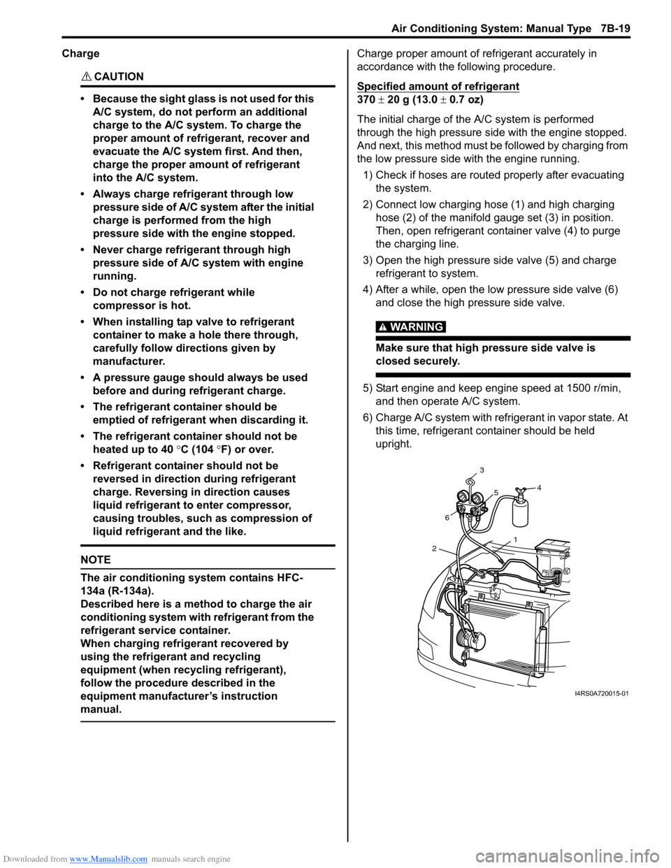
1) Check if hoses are routed properly after evacuating the system.
2) Connect low charging hose (1) and high charging hose (2) of the manifold gauge set (3) in position.
Then, open refrigerant container valve (4) to purge
the charging line.
3) Open the high pressure side valve (5) and charge refrigerant to system.
4) After a while, open the low pressure side valve (6) and close the high pressure side valve.
WARNING!
Make sure that high pressure side valve is
closed securely.
5) Start engine and keep engine speed at 1500 r/min, and then operate A/C system.
6) Charge A/C system with refrigerant in vapor state. At this time, refrigerant container should be held
upright.
1
2 6 3
5 4
I4RS0A720015-01
Page 982 of 1496

Downloaded from www.Manualslib.com manuals search engine 7B-34 Air Conditioning System: Automatic Type
Automatic Type
Precautions
A/C System CautionS7RS0B7220001
Refer to “A/C System Caution”.
Precautions in Diagnosing TroubleS7RS0B7220002
• Do not disconnect couplers from HVAC control module, battery cable from battery, HVAC control module ground
wire harness from body or main fuse before confirming diagnostic information (diagnostic trouble code) stored in
HVAC control module memory.
• Diagnostic information (diagnostic trouble code) stored in HVAC control module can be checked by display of HVAC
control module. Also, it can be checked by using SU ZUKI scan tool. Before checking diagnostic information
(diagnostic trouble code), read this manual and operator's manual for SUZUKI scan tool to know how to read
diagnostic information (diagnostic trouble code).
• When trouble is diagnosed using diagnostic information (diagnostic trouble code) on display of HVAC control
module, keep in your mind that each diagnostic inform ation (diagnostic trouble code) has priority, and only
diagnostic information (diagnostic troub le code) which has the highest priority is indicated. Therefore, after
troubleshooting the malfunction, make sure if there exists any other diagnostic information (diagnostic trouble
code).
• Be sure to read “Precautions for Electrical Circuit Service in Section 00” before inspection.
Precautions on Servicing A/C SystemS7RS0B7220003
Refer to “Precautions on Servicing A/C System”.
General Description
Auto A/C System DescriptionS7RS0B7221001
The automatic type air conditioning system (auto A/C) is pr ovided with the function to automatically control the inside
air temperature, fan speed, air flow outl et direction and air intake position by HVAC control module in addition to
functions of the manual type air conditioning system (manua l A/C). Once the inside air temperature is set using the
temperature selector, HVAC control module automatically controls the inside air temperature at the constant level at all
times based on the inside air temperature, outside ai r temperature, amount of sunlight and engine coolant
temperature detected respectively by the inside air te mperature sensor, outside air temperature sensor, sunload
sensor and ECT sensor. At this time, “FULL AUTO A/ C” appears on the display of HVAC control module.
With the air intake selector pushed in the above state, it is possible to select any position of the air intake actuator.
Then, “FULL AUTO A/C” on the display changes to “AUTO A/C”.
Page 991 of 1496
Downloaded from www.Manualslib.com manuals search engine Air Conditioning System: Automatic Type 7B-43
Not Using SUZUKI Scan Tool
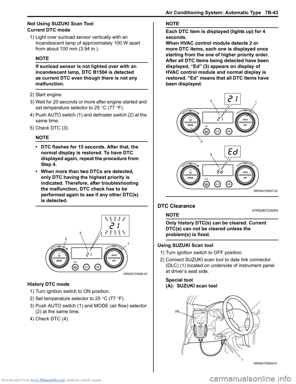
Current DTC mode1) Light over sunload sensor vertically with an incandescent lamp of approximately 100 W apart
from about 100 mm (3.94 in.).
NOTE
If sunload sensor is not lighted over with an
incandescent lamp, DTC B1504 is detected
as current DTC even though there is not any
malfunction.
2) Start engine.
3) Wait for 20 seconds or more after engine started and set temperature selector to 25 °C (77 °F).
4) Push AUTO switch (1) and defroster switch (2) at the same time.
5) Check DTC (3).
NOTE
• DTC flashes for 15 seconds. After that, the normal display is rest ored. To have DTC
displayed again, repeat the procedure from
Step 4.
• When more than two DTCs are detected, only DTC having the highest priority is
indicated. Therefore, after troubleshooting
the malfunction, DTC check has to be
performed again to see if any other DTC(s)
is detected.
History DTC mode
1) Turn ignition switch to ON position.
2) Set temperature selector to 25 °C (77 °F).
3) Push AUTO switch (1) and MODE (air flow) selector
(2) at the same time.
4) Check DTC (4).
NOTE
Each DTC item is displayed (lights up) for 4
seconds.
When HVAC control module detects 2 or
more DTC items, each one is displayed once
starting from the one of higher priority order.
After all DTC items being detected have been
displayed, “Ed” (3) appears on display of
HVAC control module and normal display is
restored. “Ed” means that all DTC items have
been displayed.
DTC ClearanceS7RS0B7224004
NOTE
Only history DTC(s) can be cleared. Current
DTC(s) can not be cleared unless the
problem(s) is fixed.
Using SUZUKI Scan tool
1) Turn ignition switch to OFF position.
2) Connect SUZUKI scan tool to data link connector (DLC) (1) located on underside of instrument panel
at driver’s seat side.
Special tool
(A): SUZUKI scan tool1
2
3
I5RS0A722006-02
1
2 34
I5RS0A722007-02
(A)
1
I5RS0A722005-01
Page 992 of 1496
Downloaded from www.Manualslib.com manuals search engine 7B-44 Air Conditioning System: Automatic Type
3) Light over sunload sensor vertically with an incandescent lamp approximately 100 W apart from
about 100 mm (3.94 in.).
NOTE
If sunload sensor is not lighted over with an
incandescent lamp, DTC B1504 is detected
as current DTC even though there is not any
malfunction.
4) Turn ignition switch to ON position.
5) Erase DTC according to instructions displayed on SUZUKI scan tool.
NOTE
To know how to use SUZUKI scan tool, refer
to operator’s manual for SUZUKI scan tool.
6) After completing the clearance, turn ignition switch to OFF position, and then di sconnect SUZUKI scan
tool from DLC.
Not Using SUZUKI Scan Tool 1) Turn ignition switch to ON position.
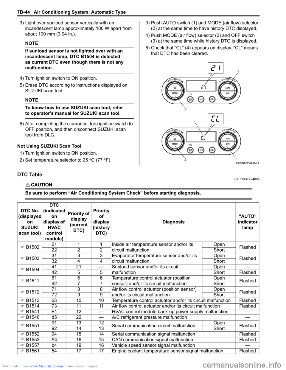
2) Set temperature selector to 25 °C (77 °F). 3) Push AUTO switch (1) and
MODE (air flow) selector
(2) at the same time to have history DTC displayed.
4) Push MODE (air flow) selector (2) and OFF switch (3) at the same time while history DTC is displayed.
5) Check that “CL” (4) appears on display. “CL” means that DTC has been cleared.
DTC TableS7RS0B7224005
CAUTION!
Be sure to perform “Air Conditioning Sy stem Check” before starting diagnosis.
1
2
3
2
4
I5RS0A722008-01
DTC No.
(displayed on
SUZUKI
scan tool) DTC
(indicated on
display of HVAC
control
module) Priority of
display
(current DTC) Priority
of
display
(history DTC) Diagnosis
“AUTO”
indicator lamp
�) B1502 21 1 1 Inside air temperature sensor and/or its
circuit malfunction Open
Flashed
22 2 2 Short
�) B1503 31 3 3 Evaporator temperature sensor and/or its
circuit malfunction Open
Flashed
32 4 4 Short
�) B1504 41 21 — Sunload sensor and/or its circuit
malfunction Open —
42 5 5 Short Flashed
�) B1511 61 6 6 Temperature control actuator (position
sensor) and/or its circuit malfunction Open
Flashed
62 7 7 Short
�) B1512 71 8 8 Air flow control actuator (position sensor)
and/or its circuit malfunction Open
Flashed
72 9 9 Short
�) B1513 63 10 10 Temperature control actuator and/or its circuit malfunction Flashed
�) B1514 73 11 11 Air flow control actuator and/or its circuit malfunction Flashed
�) B1541 E1 12 — HVAC control module back-up power supply malfunction —
�) B1546 d5 22 — A/C refrigerant pressure malfunction —
�) B1551 91 13 12
Serial communication circuit malfunction Open
Flashed
92 14 13 Short
�) B1552 94 15 14 Serial communication signal malfunction Flashed
�) B1553 A4 16 15 CAN communication signal malfunction Flashed
�) B1557 b4 19 16 Vehicle speed sensor signal malfunction —
�) B1561 54 17 17 Engine coolant temperature sensor signal malfunction Flashed
Page 993 of 1496
Downloaded from www.Manualslib.com manuals search engine Air Conditioning System: Automatic Type 7B-45
NOTE
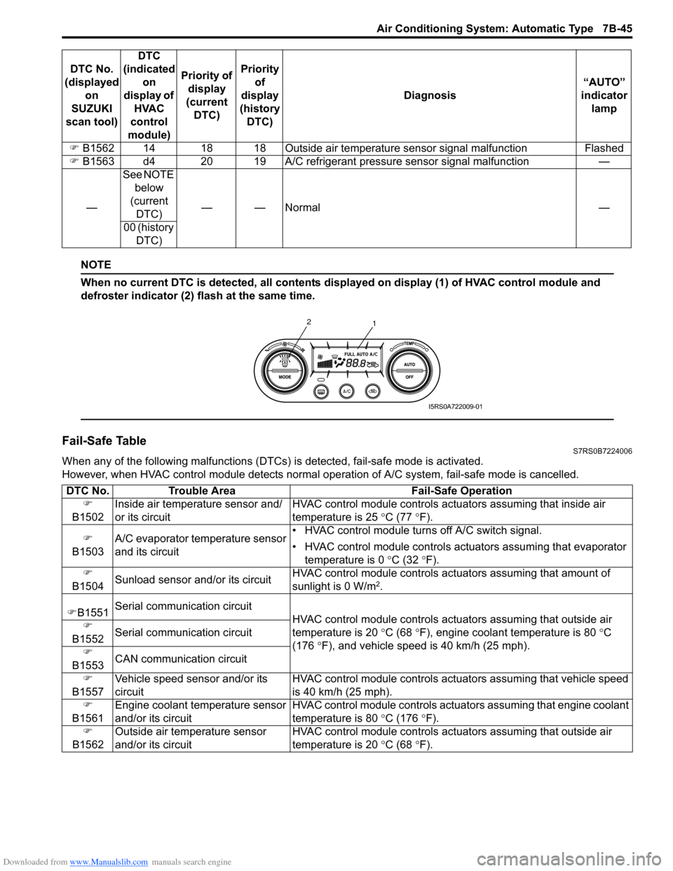
When no current DTC is detected, all contents displayed on display (1) of HVAC control module and
defroster indicator (2) flash at the same time.
Fail-Safe TableS7RS0B7224006
When any of the following malfunctions (DTCs) is detected, fail-safe mode is activated.
However, when HVAC control module detects normal ope ration of A/C system, fail-safe mode is cancelled.
�)
B1562 14 18 18 Outside air temperatur e sensor signal malfunction Flashed
�) B1563 d4 20 19 A/C refrigerant pressure sensor signal malfunction —
— See NOTE
below
(current DTC) ——Normal —
00 (history DTC)
DTC No.
(displayed on
SUZUKI
scan tool) DTC
(indicated on
display of HVAC
control
module) Priority of
display
(current DTC) Priority
of
display
(history DTC) Diagnosis
“AUTO”
indicator lamp
1
2
I5RS0A722009-01
DTC No.
Trouble Area Fail-Safe Operation
�)
B1502 Inside air temperature sensor and/
or its circuit HVAC control module controls actu
ators assuming that inside air
temperature is 25 ° C (77 °F).
�)
B1503 A/C evaporator temperature sensor
and its circuit • HVAC control module turn
s off A/C switch signal.
• HVAC control module controls actu ators assuming that evaporator
temperature is 0 ° C (32 °F).
�)
B1504 Sunload sensor and/or its circuit HVAC control module controls actu
ators assuming that amount of
sunlight is 0 W/m
2.
�) B1551 Serial communication circuit
HVAC control module controls actuators assuming that outside air
temperature is 20 ° C (68 °F), engine coolant temperature is 80 °C
(176 °F), and vehicle speed is 40 km/h (25 mph).
�)
B1552 Serial communication circuit
�)
B1553 CAN communication circuit
�)
B1557 Vehicle speed sensor and/or its
circuit HVAC control module controls act
uators assuming that vehicle speed
is 40 km/h (25 mph).
�)
B1561 Engine coolant temperature sensor
and/or its circuit HVAC control module controls act
uators assuming that engine coolant
temperature is 80 ° C (176 °F).
�)
B1562 Outside air temperature sensor
and/or its circuit HVAC control module controls actu
ators assuming that outside air
temperature is 20 ° C (68 °F).
Page 997 of 1496
Downloaded from www.Manualslib.com manuals search engine Air Conditioning System: Automatic Type 7B-49
Step 7. Final confirmation test
Confirm if the problem symptom is troubleshoot and the A/C system is free from any abnormal conditions. If there
existed DTC, clear the DTC. Then , check if the DTC is still detected and if there is any other DTC.
Visual InspectionS7RS0B7224009
Check visually the following parts and systems.
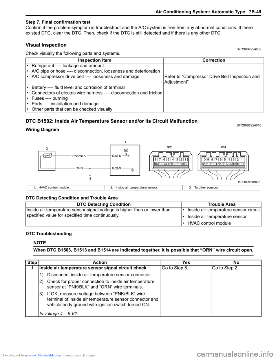
DTC B1502: Inside Air Temperature Sensor and/or Its Circuit MalfunctionS7RS0B7224010
Wiring Diagram
DTC Detecting Condition and Trouble Area
DTC Troubleshooting
NOTE
When DTC B1503, B1513 and B1514 are indicated together, it is possible that “ORN” wire circuit open.
Inspection item Correction
• Refrigerant ---- leakage and amount
• A/C pipe or hose ---- disconnection, looseness and deterioration
• A/C compressor drive belt ---- looseness and damage Refer to “Compressor Drive Belt Inspection and
Adjustment”.
• Battery ---- fluid level and corrosion of terminal
• Connectors of electric wire harn ess ---- disconnection and friction
• Fuses ---- burning
• Parts ---- installation and damage
• Other parts that can be checked visually
5V
PNK/BLK
ORN G52-6
G52-3
2
1
3
7812910
65 431516 14 13 12 11
G52
789101920121112
65 431718 16 15 14 13
G51
I5RS0A722010-01
1. HVAC control module
2. Inside air temperature sensor 3. To other sensors
DTC Detecting Condition Trouble Area
Inside air temperature sensor signal voltage is higher than or lower than
specified value for specified time continuously. • Inside air temperature sensor circuit
• Inside air temperature sensor
• HVAC control module
Step
Action YesNo
1 Inside air temperature sensor signal circuit check
1) Disconnect inside air temperature sensor connector.
2) Check for proper connection to inside air temperature
sensor at “PNK/BLK” and “ORN” wire terminals.
3) If OK, measure voltage between “PNK/BLK” wire terminal of inside air temp erature sensor connector and
vehicle body ground with ignition switch turned ON.
Is voltage 4 – 6 V? Go to Step 5.
Go to Step 2.