2006 SUZUKI SWIFT High voltage
[x] Cancel search: High voltagePage 917 of 1496
Downloaded from www.Manualslib.com manuals search engine Power Assisted Steering System: 6C-35
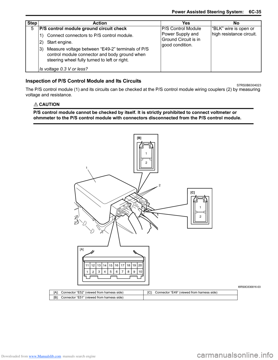
Inspection of P/S Control Module and Its CircuitsS7RS0B6304023
The P/S control module (1) and its circuits can be checked at the P/S control module wiring couplers (2) by measuring
voltage and resistance.
CAUTION!
P/S control module cannot be checked by itself. It is strictly prohibited to connect voltmeter or
ohmmeter to the P/S control module with connectors disconnected from the P/S control module.
5 P/S control module ground circuit check
1) Connect connectors to P/S control module.
2) Start engine.
3) Measure voltage between “E49-2” terminals of P/S
control module connector and body ground when
steering wheel fully turned to left or right.
Is voltage 0.3 V or less? P/S Control Module
Power Supply and
Ground Circuit is in
good condition.
“BLK” wire is open or
high resistance circuit.
Step Action Yes No
[A]
12
3
4 5 67
89
11
10
12 13
141516
17 18 19 20
[B]
[C]
12
1
1 2
2
I6RS0C630016-03
[A]: Connector “E52” (viewed from harness side) [C]: Connector “E49” (viewed from harness side)
[B]: Connector “E51” (viewed from harness side)
Page 958 of 1496

Downloaded from www.Manualslib.com manuals search engine 7B-10 Air Conditioning System: Manual Type
Abnormal Noise from Tension Pulley
Abnormal Noise from A/C Evaporator
Abnormal Noise from Blower Motor
A/C System Performance InspectionS7RS0B7214003
1) Confirm that vehicle and environmental conditions are as follows.
• Vehicle is put indoors.
• Ambient temperature is within 25 – 35 °C (77 – 95
° F).
• Relative humidity is within 30 – 70%.
• There is no wind indoors.
• HVAC unit is normal.
• Blower motor is normal.
• There is no air leakage from air ducts.
• Condenser fins are clean.
• Air filter in HVAC unit is not clogged with dirt and
dust.
• Battery voltage is about 12 V.
• Radiator cooling fan operates normally.
2) Make sure that high pressure valve (1) and low pressure valve (2) of manifold gauge are firmly
closed.
3) Connect high pressure charging hose (3) to high pressure service valve (5) on vehicle and low
pressure charging hose (4) to low pressure service
valve (6).
4) Bleed the air in charging hoses (3) and (4) by loosening their nuts respectively utilizing the
refrigerant pressure. When a hissing sound is heard,
immediately tighten nut.
CAUTION!
Do not connect high and low pressure
charging hoses in reverse.
Condition Possible cause Correction / Reference Item
Clattering noise is heard
from pulley Worn or damaged bearing
Replace tension pulley.
Pulley cranks upon
contact Cracked or loose bracket
Replace or retighten bracket.
ConditionPossible cause Correction / Reference Item
Whistling sound is heard
from A/C evaporator Depending on the combination of the
interior / exterior temperatures, engine
rpm and refrigerant pressure, the
refrigerant flowing out of the expansion
valve may, under certain conditions,
make a whistling sound At times, slightly decrea
sing refrigerant volume
may stop this noise.
Inspect expansion valve and replace if faulty.
Condition Possible cause Correction / Reference Item
Blower motor emits a
chirping sound in
proportion to its speed of
rotation Worn or damaged motor brushes or
commutator
Replace blower motor.
Fluttering noise or large
droning noise is heard
from blower motor Leaves or other debris introduced from
fresh air inlet to blower motor
Remove debris and make sure that the screen
at fresh air inlet is intact.
53
2
1
4 6
I4RS0A720006-01
Page 963 of 1496
Downloaded from www.Manualslib.com manuals search engine Air Conditioning System: Manual Type 7B-15
A/C System Inspection at ECMS7RS0B7214004
Voltage Check
When checking voltage at ECM connector terminals related to A/C system, refer to “DTC P2101: Throttle Actuator
Control Motor Circuit Range / Performance in Section 1A”.
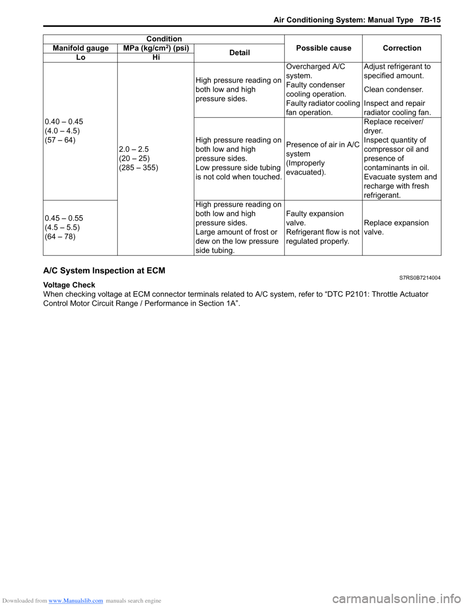
0.40 – 0.45
(4.0 – 4.5)
(57 – 64)
2.0 – 2.5
(20 – 25)
(285 – 355) High pressure reading on
both low and high
pressure sides.
Overcharged A/C
system.
Adjust refrigerant to
specified amount.
Faulty condenser
cooling operation. Clean condenser.
Faulty radiator cooling
fan operation. Inspect and repair
radiator cooling fan.
High pressure reading on
both low and high
pressure sides.
Low pressure side tubing
is not cold when touched. Presence of air in A/C
system
(Improperly
evacuated).Replace receiver/
dryer.
Inspect quantity of
compressor oil and
presence of
contaminants in oil.
Evacuate system and
recharge with fresh
refrigerant.
0.45 – 0.55
(4.5 – 5.5)
(64 – 78) High pressure reading on
both low and high
pressure sides.
Large amount of frost or
dew on the low pressure
side tubing.Faulty expansion
valve.
Refrigerant flow is not
regulated properly.
Replace expansion
valve.
Condition
Possible cause Correction
Manifold gauge MPa (kg/cm
2) (psi)
Detail
Lo Hi
Page 997 of 1496
Downloaded from www.Manualslib.com manuals search engine Air Conditioning System: Automatic Type 7B-49
Step 7. Final confirmation test
Confirm if the problem symptom is troubleshoot and the A/C system is free from any abnormal conditions. If there
existed DTC, clear the DTC. Then , check if the DTC is still detected and if there is any other DTC.
Visual InspectionS7RS0B7224009
Check visually the following parts and systems.
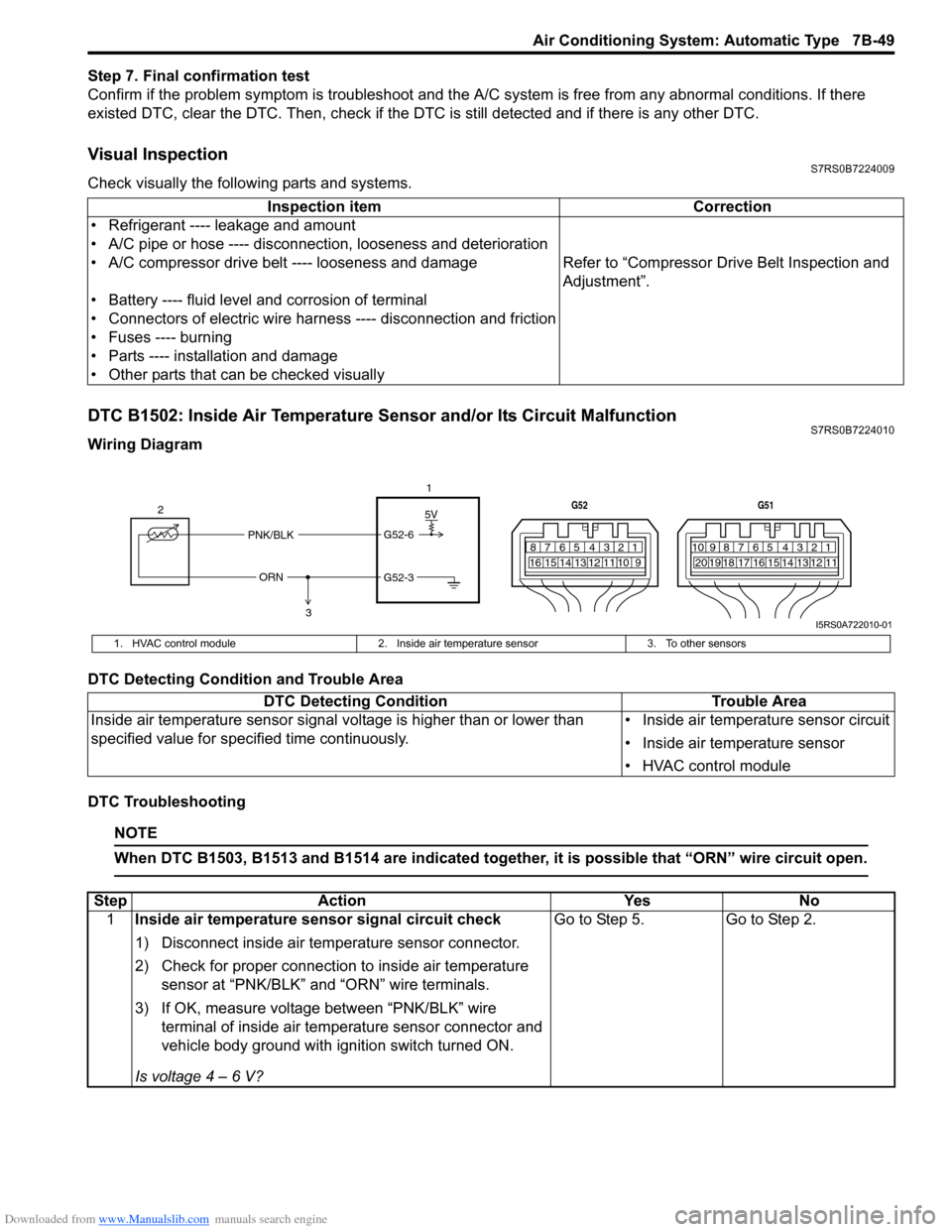
DTC B1502: Inside Air Temperature Sensor and/or Its Circuit MalfunctionS7RS0B7224010
Wiring Diagram
DTC Detecting Condition and Trouble Area
DTC Troubleshooting
NOTE
When DTC B1503, B1513 and B1514 are indicated together, it is possible that “ORN” wire circuit open.
Inspection item Correction
• Refrigerant ---- leakage and amount
• A/C pipe or hose ---- disconnection, looseness and deterioration
• A/C compressor drive belt ---- looseness and damage Refer to “Compressor Drive Belt Inspection and
Adjustment”.
• Battery ---- fluid level and corrosion of terminal
• Connectors of electric wire harn ess ---- disconnection and friction
• Fuses ---- burning
• Parts ---- installation and damage
• Other parts that can be checked visually
5V
PNK/BLK
ORN G52-6
G52-3
2
1
3
7812910
65 431516 14 13 12 11
G52
789101920121112
65 431718 16 15 14 13
G51
I5RS0A722010-01
1. HVAC control module
2. Inside air temperature sensor 3. To other sensors
DTC Detecting Condition Trouble Area
Inside air temperature sensor signal voltage is higher than or lower than
specified value for specified time continuously. • Inside air temperature sensor circuit
• Inside air temperature sensor
• HVAC control module
Step
Action YesNo
1 Inside air temperature sensor signal circuit check
1) Disconnect inside air temperature sensor connector.
2) Check for proper connection to inside air temperature
sensor at “PNK/BLK” and “ORN” wire terminals.
3) If OK, measure voltage between “PNK/BLK” wire terminal of inside air temp erature sensor connector and
vehicle body ground with ignition switch turned ON.
Is voltage 4 – 6 V? Go to Step 5.
Go to Step 2.
Page 998 of 1496
Downloaded from www.Manualslib.com manuals search engine 7B-50 Air Conditioning System: Automatic Type
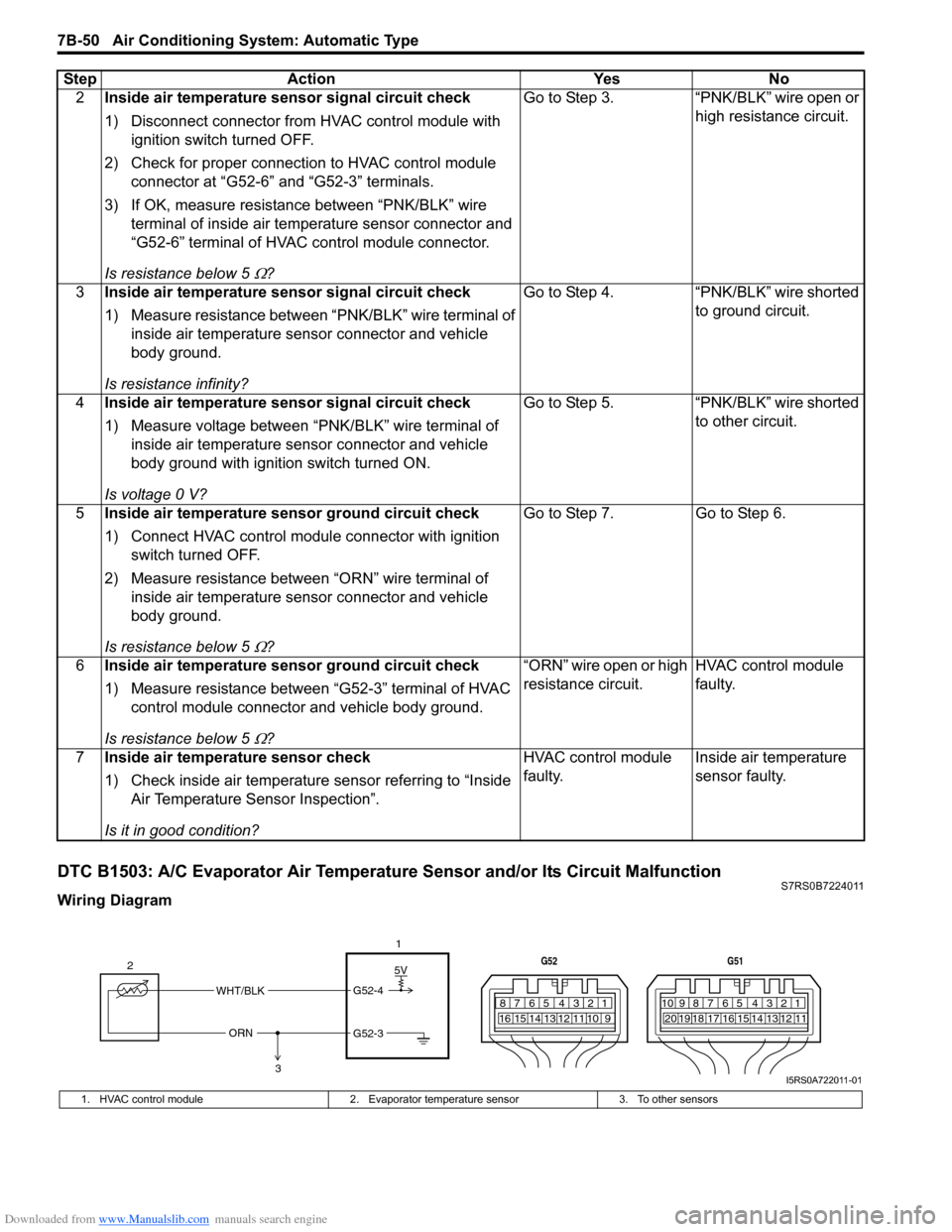
DTC B1503: A/C Evaporator Air Temperature Sensor and/or Its Circuit MalfunctionS7RS0B7224011
Wiring Diagram2
Inside air temperature sensor signal circuit check
1) Disconnect connector from HVAC control module with
ignition switch turned OFF.
2) Check for proper connection to HVAC control module connector at “G52-6” and “G52-3” terminals.
3) If OK, measure resistance between “PNK/BLK” wire terminal of inside air temp erature sensor connector and
“G52-6” terminal of HVAC control module connector.
Is resistance below 5
Ω? Go to Step 3. “PNK/BLK” wire open or
high resistance circuit.
3 Inside air temperature sensor signal circuit check
1) Measure resistance between “PNK/BLK” wire terminal of
inside air temperature sensor connector and vehicle
body ground.
Is resistance infinity? Go to Step 4.
“PNK/BLK” wire shorted
to ground circuit.
4 Inside air temperature sensor signal circuit check
1) Measure voltage between “PNK/BLK” wire terminal of
inside air temperature sensor connector and vehicle
body ground with ignition switch turned ON.
Is voltage 0 V? Go to Step 5.
“PNK/BLK” wire shorted
to other circuit.
5 Inside air temperature sensor ground circuit check
1) Connect HVAC control module connector with ignition
switch turned OFF.
2) Measure resistance between “ORN” wire terminal of inside air temperature sensor connector and vehicle
body ground.
Is resistance below 5
Ω? Go to Step 7. Go to Step 6.
6 Inside air temperature sensor ground circuit check
1) Measure resistance between “G52-3” terminal of HVAC
control module connector and vehicle body ground.
Is resistance below 5
Ω? “ORN” wire open or high
resistance circuit.
HVAC control module
faulty.
7 Inside air temperature sensor check
1) Check inside air temperature sensor referring to “Inside
Air Temperature Sensor Inspection”.
Is it in good condition? HVAC control module
faulty.
Inside air temperature
sensor faulty.
Step Action Yes No
5V
WHT/BLK
ORN G52-4
G52-3
2
1
3
7812910
65 431516 14 13 12 11
G52
789101920121112
65 431718 16 15 14 13
G51
I5RS0A722011-01
1. HVAC control module
2. Evaporator temperature sensor 3. To other sensors
Page 999 of 1496
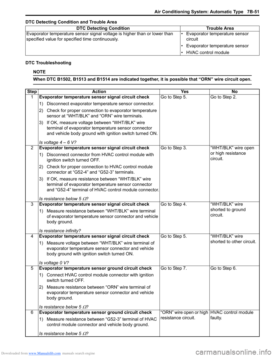
Downloaded from www.Manualslib.com manuals search engine Air Conditioning System: Automatic Type 7B-51
DTC Detecting Condition and Trouble Area
DTC Troubleshooting
NOTE
When DTC B1502, B1513 and B1514 are indicated together, it is possible that “ORN” wire circuit open.
DTC Detecting ConditionTrouble Area
Evaporator temperature sensor signal voltage is higher than or lower than
specified value for specified time continuously. • Evaporator temperature sensor
circuit
• Evaporator temperature sensor
• HVAC control module
Step Action YesNo
1 Evaporator temperature sensor signal circuit check
1) Disconnect evaporator temperature sensor connector.
2) Check for proper connection to evaporator temperature
sensor at “WHT/BLK” and “ORN” wire terminals.
3) If OK, measure voltage between “WHT/BLK” wire terminal of evaporator te mperature sensor connector
and vehicle body ground with ignition switch turned ON.
Is voltage 4 – 6 V? Go to Step 5.
Go to Step 2.
2 Evaporator temperature sensor signal circuit check
1) Disconnect connector from HVAC control module with
ignition switch turned OFF.
2) Check for proper connection to HVAC control module connector at “G52-4” and “G52-3” terminals.
3) If OK, measure resistance between “WHT/BLK” wire terminal of evaporator te mperature sensor connector
and “G52-4” terminal of HVAC control module connector.
Is resistance below 5
Ω? Go to Step 3. “WHT/BLK” wire open
or high resistance
circuit.
3 Evaporator temperature sensor signal circuit check
1) Measure resistance between “WHT/BLK” wire terminal
of evaporator temperature sensor connector and vehicle
body ground.
Is resistance infinity? Go to Step 4. “WHT/BLK” wire
shorted to ground
circuit.
4 Evaporator temperature sensor signal circuit check
1) Measure voltage between “WHT/BLK” wire terminal of
evaporator temperature sens or connector and vehicle
body ground with ignition switch turned ON.
Is voltage 0 V? Go to Step 5. “WHT/BLK” wire
shorted to other circuit.
5 Evaporator temperature sensor ground circuit check
1) Connect HVAC control module connector with ignition
switch turned OFF.
2) Measure resistance between “ORN” wire terminal of evaporator temperature sens or connector and vehicle
body ground.
Is resistance below 5
Ω? Go to Step 7. Go to Step 6.
6 Evaporator temperature sensor ground circuit check
1) Measure resistance between “G52-3” terminal of HVAC
control module connector and vehicle body ground.
Is resistance below 5
Ω? “ORN” wire open or high
resistance circuit.
HVAC control module
faulty.
Page 1000 of 1496
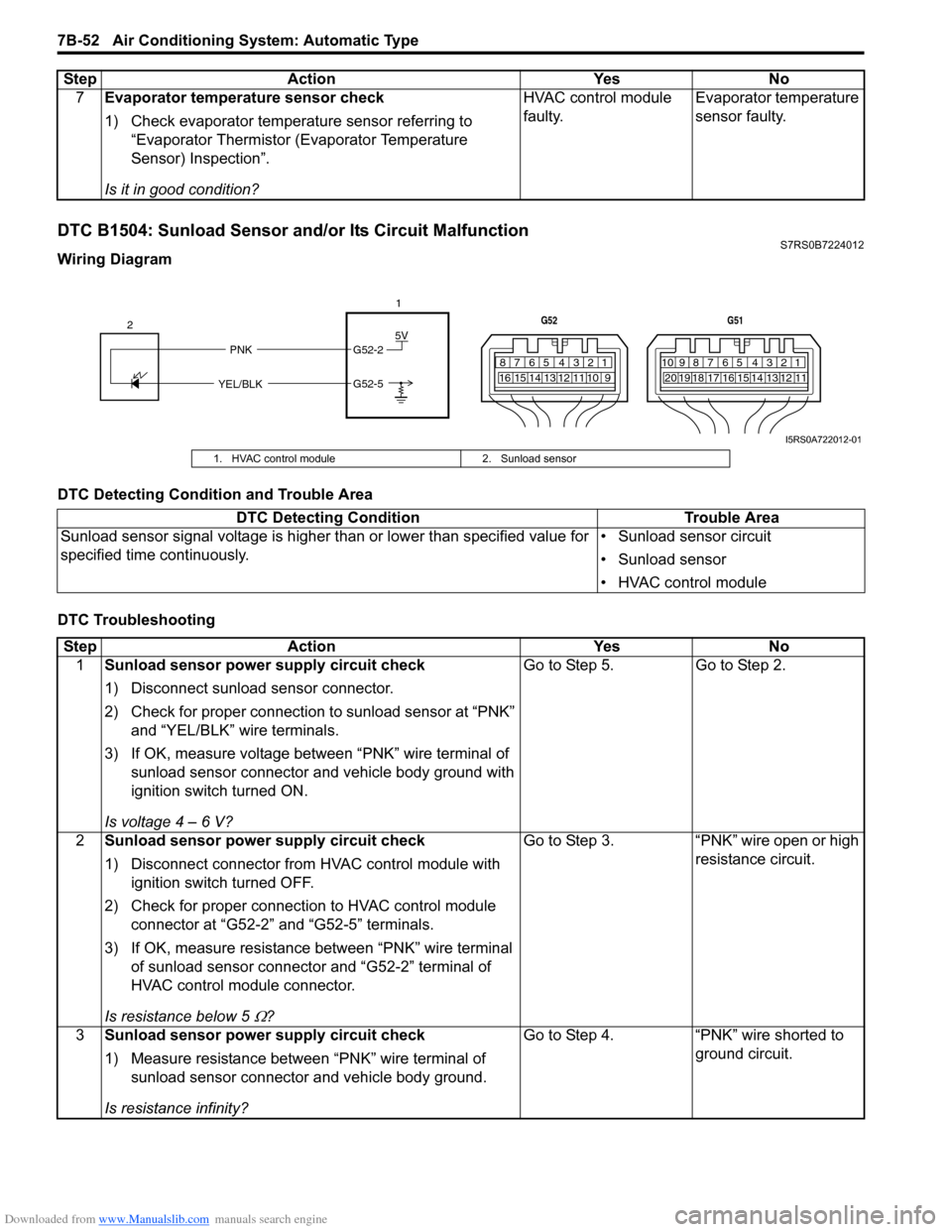
Downloaded from www.Manualslib.com manuals search engine 7B-52 Air Conditioning System: Automatic Type
DTC B1504: Sunload Sensor and/or Its Circuit MalfunctionS7RS0B7224012
Wiring Diagram
DTC Detecting Condition and Trouble Area
DTC Troubleshooting7
Evaporator temperature sensor check
1) Check evaporator temperature sensor referring to
“Evaporator Thermistor (Evaporator Temperature
Sensor) Inspection”.
Is it in good condition? HVAC control module
faulty.
Evaporator temperature
sensor faulty.
Step Action Yes No
5V
PNK G52-2
G52-5
YEL/BLK
2
1
7812910
65 431516 14 13 12 11
G52
789101920121112
65 431718 16 15 14 13
G51
I5RS0A722012-01
1. HVAC control module
2. Sunload sensor
DTC Detecting Condition Trouble Area
Sunload sensor signal voltage is higher than or lower than specified value for
specified time continuously. • Sunload sensor circuit
• Sunload sensor
• HVAC control module
Step
Action YesNo
1 Sunload sensor power supply circuit check
1) Disconnect sunload sensor connector.
2) Check for proper connection to sunload sensor at “PNK”
and “YEL/BLK” wire terminals.
3) If OK, measure voltage between “PNK” wire terminal of sunload sensor connector and vehicle body ground with
ignition switch turned ON.
Is voltage 4 – 6 V? Go to Step 5.
Go to Step 2.
2 Sunload sensor power supply circuit check
1) Disconnect connector from HVAC control module with
ignition switch turned OFF.
2) Check for proper connection to HVAC control module connector at “G52-2” and “G52-5” terminals.
3) If OK, measure resistance between “PNK” wire terminal of sunload sensor connector and “G52-2” terminal of
HVAC control module connector.
Is resistance below 5
Ω? Go to Step 3. “PNK” wire open or high
resistance circuit.
3 Sunload sensor power supply circuit check
1) Measure resistance between “PNK” wire terminal of
sunload sensor connector and vehicle body ground.
Is resistance infinity? Go to Step 4. “PNK” wire shorted to
ground circuit.
Page 1001 of 1496
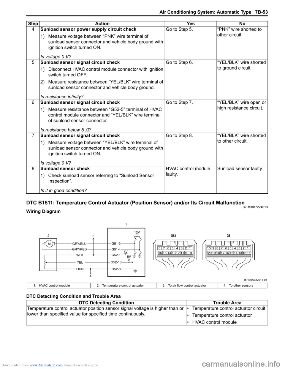
Downloaded from www.Manualslib.com manuals search engine Air Conditioning System: Automatic Type 7B-53
DTC B1511: Temperature Control Actuator (Position Sensor) and/or Its Circuit MalfunctionS7RS0B7224013
Wiring Diagram
DTC Detecting Condition and Trouble Area4
Sunload sensor power supply circuit check
1) Measure voltage between “PNK” wire terminal of
sunload sensor connector and vehicle body ground with
ignition switch turned ON.
Is voltage 0 V? Go to Step 5. “PNK” wire shorted to
other circuit.
5 Sunload sensor signal circuit check
1) Disconnect HVAC control modul e connector with ignition
switch turned OFF.
2) Measure resistance between “YEL/BLK” wire terminal of sunload sensor connector and vehicle body ground.
Is resistance infinity? Go to Step 6. “YEL/BLK” wire shorted
to ground circuit.
6 Sunload sensor signal circuit check
1) Measure resistance between “G52-5” terminal of HVAC
control module connector and “YEL/BLK” wire terminal
of sunload sensor connector.
Is resistance below 5
Ω? Go to Step 7. “YEL/BLK” wire open or
high resistance circuit.
7 Sunload sensor signal circuit check
1) Measure voltage between “YEL/BLK” wire terminal of
sunload sensor connector and vehicle body ground with
ignition switch turned ON.
Is voltage 0 V? Go to Step 8.
“YEL/BLK” wire shorted
to other circuit.
8 Sunload sensor check
1) Check sunload sensor referring to “Sunload Sensor
Inspection”.
Is it in good condition? HVAC control module
faulty.
Sunload sensor faulty.
Step
Action YesNo
7812910
65 431516 14 13 12 11
G52
789101920121112
65 431718 16 15 14 13
G51
M 12V
5V 5V
YEL
WHT
GRY/BLU
GRY/RED
2
1
ORN
G51-3
G51-4
G52-1
G52-13
G52-3
3
4
I5RS0A722013-01
1. HVAC control module 2. Temperature control actuator 3. To air flow control actuator4. To other sensors
DTC Detecting Condition Trouble Area
Temperature control actuator position sensor signal voltage is higher than or
lower than specified value for specified time continuously. • Temperature control actuator circuit
• Temperature control actuator
• HVAC control module