2006 SUZUKI SWIFT ppl
[x] Cancel search: pplPage 396 of 1496
Downloaded from www.Manualslib.com manuals search engine 1H-4 Ignition System:
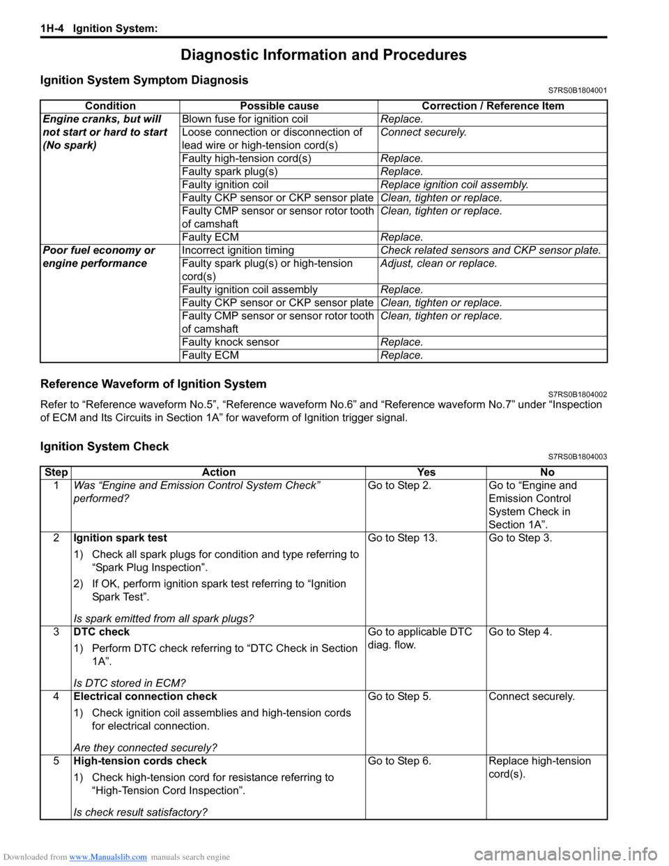
Diagnostic Information and Procedures
Ignition System Symptom DiagnosisS7RS0B1804001
Reference Waveform of Ignition SystemS7RS0B1804002
Refer to “Reference waveform No.5”, “Reference waveform No.6” and “Reference waveform No.7” under “Inspection
of ECM and Its Circuits in Section 1A” for waveform of Ignition trigger signal.
Ignition System CheckS7RS0B1804003
Condition Possible cause Correction / Reference Item
Engine cranks, but will
not start or hard to start
(No spark) Blown fuse for ignition coil
Replace.
Loose connection or disconnection of
lead wire or high-tension cord(s) Connect securely.
Faulty high-tension cord(s) Replace.
Faulty spark plug(s) Replace.
Faulty ignition coil Replace ignition coil assembly.
Faulty CKP sensor or CKP sensor plate Clean, tighten or replace.
Faulty CMP sensor or sensor rotor tooth
of camshaft Clean, tighten or replace.
Faulty ECM Replace.
Poor fuel economy or
engine performance Incorrect ignition timing
Check related sensors and CKP sensor plate.
Faulty spark plug(s) or high-tension
cord(s) Adjust, clean or replace.
Faulty ignition coil assembly Replace.
Faulty CKP sensor or CKP sensor plate Clean, tighten or replace.
Faulty CMP sensor or sensor rotor tooth
of camshaft Clean, tighten or replace.
Faulty knock sensor Replace.
Faulty ECM Replace.
StepAction YesNo
1 Was “Engine and Emission Control System Check”
performed? Go to Step 2.
Go to “Engine and
Emission Control
System Check in
Section 1A”.
2 Ignition spark test
1) Check all spark plugs for condition and type referring to
“Spark Plug Inspection”.
2) If OK, perform ignition spark test referring to “Ignition Spar k Tes t”.
Is spark emitted from all spark plugs? Go to Step 13. Go to Step 3.
3 DTC check
1) Perform DTC check referring to “DTC Check in Section
1A”.
Is DTC stored in ECM? Go to applicable DTC
diag. flow.
Go to Step 4.
4 Electrical connection check
1) Check ignition coil assemblies and high-tension cords
for electrical connection.
Are they connected securely? Go to Step 5.
Connect securely.
5 High-tension cords check
1) Check high-tension cord for resistance referring to
“High-Tension Cord Inspection”.
Is check result satisfactory? Go to Step 6.
Replace high-tension
cord(s).
Page 397 of 1496

Downloaded from www.Manualslib.com manuals search engine Ignition System: 1H-5
6Ignition coil assembly power supply and ground circuit
check
1) Check ignition coil assembly power supply and ground
circuits for open and short.
Are circuits in good condition? Go to Step 7.
Repair or replace.
7 Ignition coil assembly check
1) Check ignition coil for resistance referring to “Ignition
Coil Assembly (Including ignitor) Inspection”.
Is check result satisfactory? Go to Step 8.
Replace ignition coil
assembly.
8 CKP sensor check
1) Check CKP sensor referring to “CKP Sensor Inspection
in Section 1C”.
Is check result satisfactory? Go to Step 9.
Tighten CKP sensor
bolt, replace CKP
sensor or CKP sensor
plate.
9 CMP sensor check
1) Check CMP sensor referring to “Camshaft Position
(CMP) Sensor Inspection in Section 1C”.
Is check result satisfactory? Go to Step 10. Tighten CMP sensor
bolt, replace CMP
sensor or intake
camshaft.
10 Ignition trigger signal circuit check
1) Check ignition trigger signal wire for open, short and
poor connection.
Is circuit in good condition? Go to Step 11. Repair or replace.
11 A known-good ignition coil assembly substitution
1) Substitute a known-good ignition coil assembly and then
repeat Step 2.
Is check result of Step 2 satisfactory? Go to Step 12. Substitute a known-
good ECM and then
repeat Step 2.
12 Knock sensor check
1) Confirm that knock sensor circuit is in good condition
referring to “DTC P0327 / P0328: Knock Sensor 1 Circuit
Low / High in Section 1A”.
2) Check oscilloscope waveform of knock sensor signal
referring to “Reference waveform No.25” and
“Reference waveform No.26” under “Inspection of ECM
and Its Circuits in Section 1A”.
Is check result satisfactory? Go to Step 13. Substitute a known-
good knock sensor and
recheck.
13 Ignition timing check
1) Check initial ignition timing and ignition timing advance
referring to “Ignition Timing Inspection”.
Is check result satisfactory? System is in good
condition.
Check CMP sensor,
CMP sensor rotor tooth
of camshaft, CKP
sensor, CKP sensor
plate and/or input
signals related to this
system.
Step
Action YesNo
Page 406 of 1496
Downloaded from www.Manualslib.com manuals search engine 1I-5 Starting System:
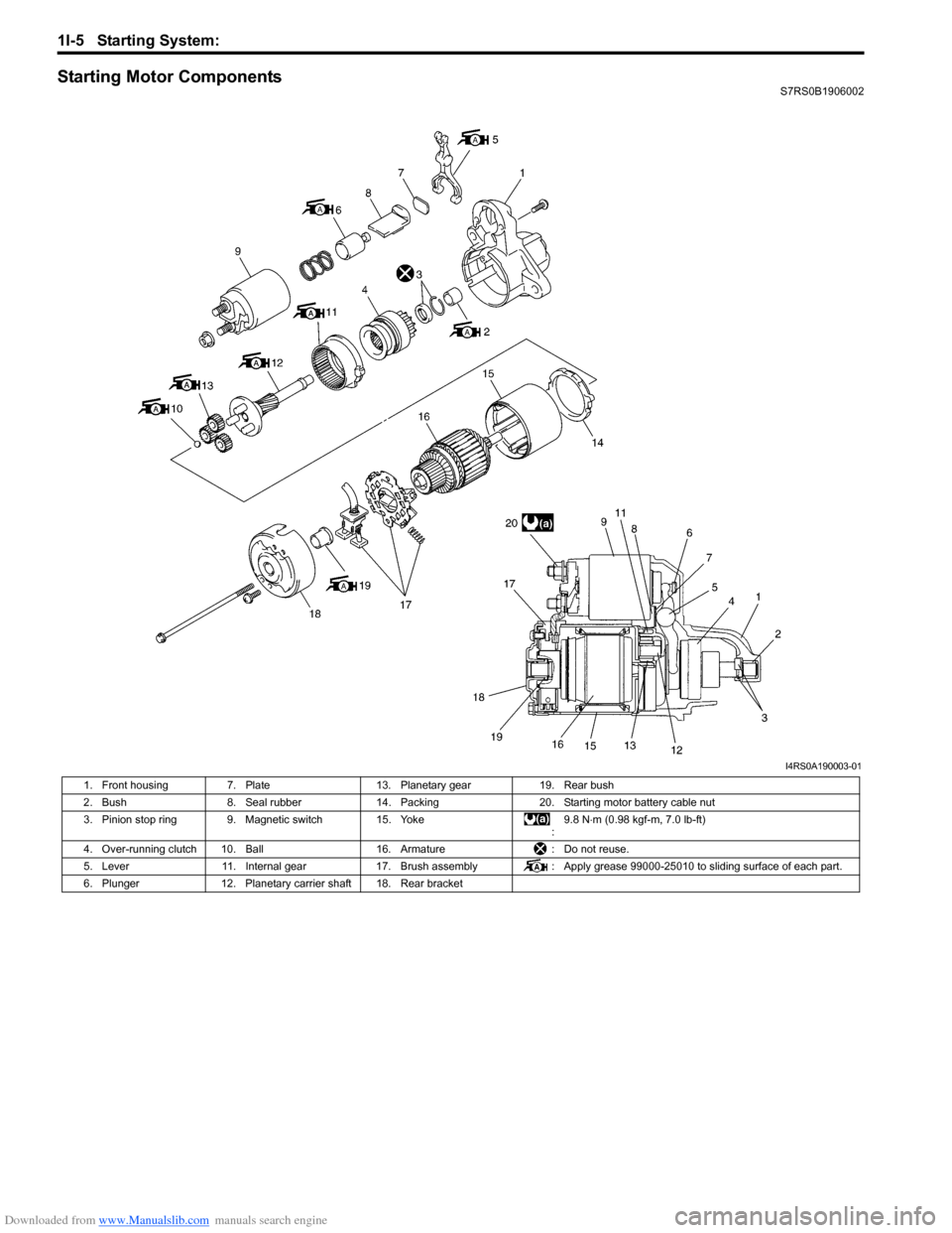
Starting Motor ComponentsS7RS0B1906002
I4RS0A190003-01
1. Front housing 7. Plate 13. Planetary gear 19. Rear bush
2. Bush 8. Seal rubber 14. Packing 20. Starting motor battery cable nut
3. Pinion stop ring 9. Magnetic switch 15. Yoke :9.8 N
⋅m (0.98 kgf-m, 7.0 lb-ft)
4. Over-running clutch 10. Ball 16. Armature: Do not reuse.
5. Lever 11. Internal gear 17. Brush assembly : Apply grease 99000-25010 to sliding surface of each part.
6. Plunger 12. Planetary carrier shaft 18. Rear bracket
Page 415 of 1496

Downloaded from www.Manualslib.com manuals search engine Charging System: 1J-5
Generator Test (Undercharged Battery Check)S7RS0B1A04003
This condition, as evidenced by slow cranking or
indicator clear with dark or light yellow dot can be
caused by one or more of the following conditions even
though indicator lamp may be operating normal.
The following procedure also applies to cars with
voltmeter and ammeter.1) Make sure that undercharged condition has not been caused by accessories left on for extended period of
time.
2) Check drive belt for proper tension.
3) If battery defect is suspected, refer to “Battery Description”.
4) Inspect wiring for defects. Check all connections for tightness and cleanliness, battery cable connections
at battery, starting motor, ignition ground cable and
no “C” terminal circuit at ground.
5) Connect switch (6), load (5), battery (4), voltmeter (3) and ammeter (2) to generator (1) as shown in
figure.
Voltmeter: Set between generator “B” terminal
and ground.
Ammeter: Set between generator “B” terminal
and battery (+) terminal.
NOTE
Use fully charged battery.
6) Measure current and voltage.
No-Load Check 1) Run engine from idling up to 2000 rpm and read meters.
NOTE
Turn off switches of all accessories (wiper,
heater etc.).
Specification for undercharged battery (No-load
check)
Current: 10 A
Voltage: 14.2 – 14.8 V (at 20 °C, 68 °F)
NOTE
Consideration should be taken that voltage
will differ somewhat with regulator case
temperature as shown in figure.
2) Using service wire, ground “C” terminal (1) of
generator.
3) Measure voltage between “B” terminal of generator and body ground.
Voltage: 12.5 – 13.1 V (at 20 °C, 68 °F)
• If voltage is higher than standard value
If voltage is higher than standard value, check ground
of brushes.
If brushes are not grounded, replace IC regulator.
If voltage is lower than standard value, proceed to the
following check.
Load Check 1) Run engine at 2000 rpm and turn on head light and blower motor.
2) Measure current. If measure current is less than 30 A, repair or
replace generator.
IYSQ011A0007-01
[A]: Regulated voltage (V)
[B]: Heat sink temperature ( °C)
16.0
15.5
15.0
14.5
14.0
13.5
13.0
-30 0 20
[A]
[B]
68
22120 (˚C)
248 (˚F)
(V)
I6RS0B1A1002-01
I5JB0A1A0011-01
Page 436 of 1496
Downloaded from www.Manualslib.com manuals search engine 2B-3 Front Suspension:
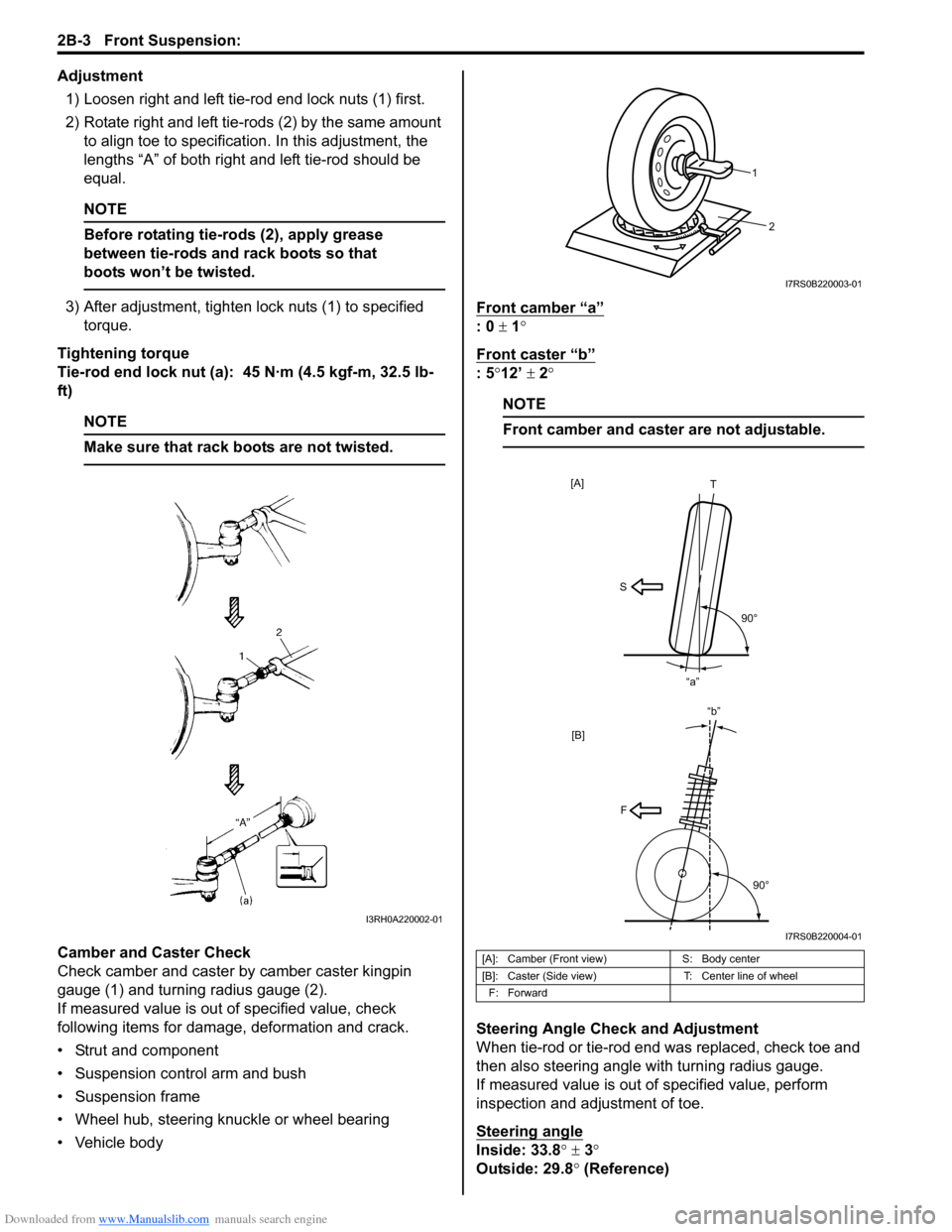
Adjustment1) Loosen right and left tie-rod end lock nuts (1) first.
2) Rotate right and left tie-rods (2) by the same amount to align toe to specification. In this adjustment, the
lengths “A” of both right and left tie-rod should be
equal.
NOTE
Before rotating tie-rods (2), apply grease
between tie-rods and rack boots so that
boots won’t be twisted.
3) After adjustment, tighten lock nuts (1) to specified torque.
Tightening torque
Tie-rod end lock nut (a): 45 N·m (4.5 kgf-m, 32.5 lb-
ft)
NOTE
Make sure that rack boots are not twisted.
Camber and Caster Check
Check camber and caster by camber caster kingpin
gauge (1) and turning radius gauge (2).
If measured value is out of specified value, check
following items for damage, deformation and crack.
• Strut and component
• Suspension control arm and bush
• Suspension frame
• Wheel hub, steering knuckle or wheel bearing
• Vehicle body Front camber “a”
: 0
± 1°
Front caster “b”
: 5 °12’ ± 2°
NOTE
Front camber and caster are not adjustable.
Steering Angle Check and Adjustment
When tie-rod or tie-rod end was replaced, check toe and
then also steering angle with turning radius gauge.
If measured value is out of specified value, perform
inspection and adjustment of toe.
Steering angle
Inside: 33.8 ° ± 3 °
Outside: 29.8 ° (Reference)
I3RH0A220002-01
[A]: Camber (Front view) S: Body center
[B]: Caster (Side view) T: Center line of wheel
F: Forward
2
1
I7RS0B220003-01
[B]
S T
90°
“a”
[A]
F
90°
“b”
I7RS0B220004-01
Page 440 of 1496
Downloaded from www.Manualslib.com manuals search engine 2B-7 Front Suspension:
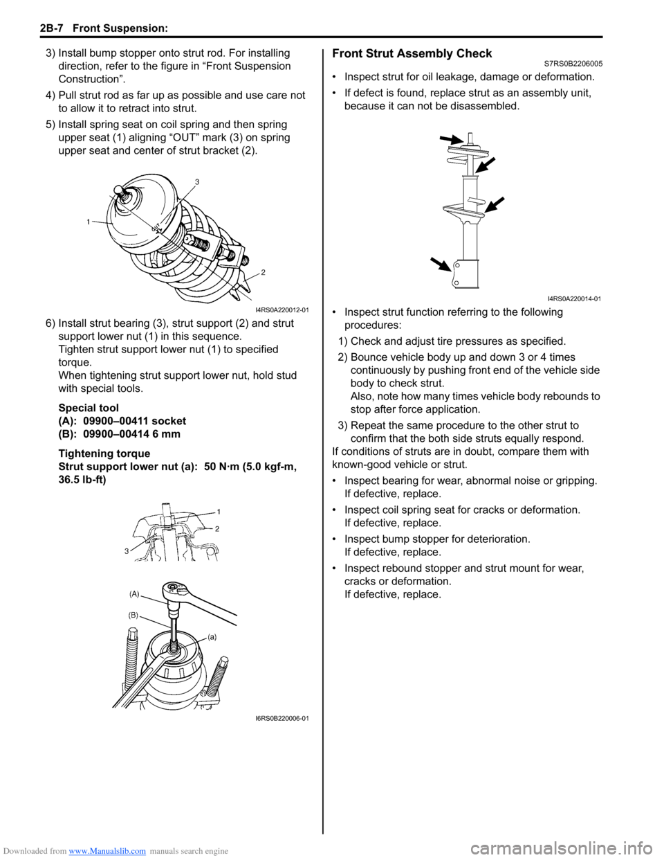
3) Install bump stopper onto strut rod. For installing
direction, refer to the figure in “Front Suspension
Construction”.
4) Pull strut rod as far up as possible and use care not to allow it to re tract into strut.
5) Install spring seat on coil spring and then spring upper seat (1) aligning “OUT” mark (3) on spring
upper seat and center of strut bracket (2).
6) Install strut bearing (3), strut support (2) and strut
support lower nut (1) in this sequence.
Tighten strut support lower nut (1) to specified
torque.
When tightening strut support lower nut, hold stud
with special tools.
Special tool
(A): 09900–00411 socket
(B): 09900–00414 6 mm
Tightening torque
Strut support lower nut (a): 50 N·m (5.0 kgf-m,
36.5 lb-ft)Front Strut Assembly CheckS7RS0B2206005
• Inspect strut for oil leakage, damage or deformation.
• If defect is found, replace strut as an assembly unit, because it can not be disassembled.
• Inspect strut function re ferring to the following
procedures:
1) Check and adjust tire pressures as specified.
2) Bounce vehicle body up and down 3 or 4 times continuously by pushing front end of the vehicle side
body to check strut.
Also, note how many times vehicle body rebounds to
stop after force application.
3) Repeat the same procedure to the other strut to confirm that the both side struts equally respond.
If conditions of struts are in doubt, compare them with
known-good vehicle or strut.
• Inspect bearing for wear, abnormal noise or gripping. If defective, replace.
• Inspect coil spring seat for cracks or deformation.
If defective, replace.
• Inspect bump stopper for deterioration. If defective, replace.
• Inspect rebound stopper and strut mount for wear, cracks or deformation.
If defective, replace.
I4RS0A220012-01
I6RS0B220006-01
I4RS0A220014-01
Page 445 of 1496
Downloaded from www.Manualslib.com manuals search engine Front Suspension: 2B-12
Front Wheel Hub, Disc, Nut and Bearing CheckS7RS0B2206008
• Inspect each wheel disc for dents, distortion and cracks.
A disc in badly damaged condition must be replaced.
• Check rust of installation face inside of wheel disc.
As rust affects adversely, remove it thoroughly.
• Check wheel nuts for tightness and, as necessary, retighten them to specification.
• Check wheel bolt press-fitted into wheel hub for wear, damage, poor thread condition, and looseness.
Replace defective bolt with a new one.
When bolt installation is found loose, replace both bolt
and wheel hub with new ones.
Tightening torque
Wheel nut: 85 N·m (8.5 kgf-m, 61.5 lb-ft)
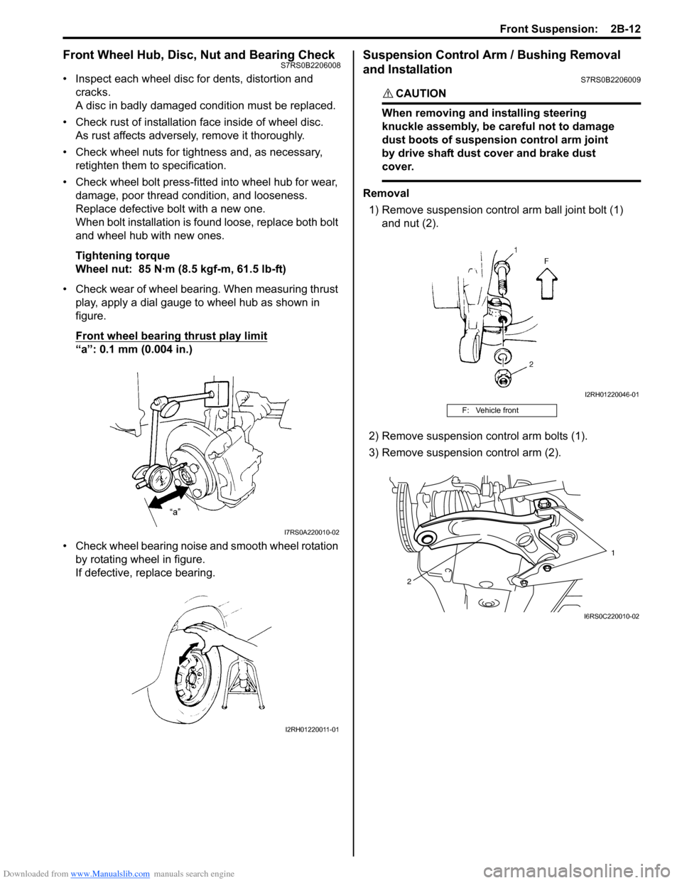
• Check wear of wheel bearing. When measuring thrust play, apply a dial gauge to wheel hub as shown in
figure.
Front wheel bearing thrust play limit
“a”: 0.1 mm (0.004 in.)
• Check wheel bearing noise and smooth wheel rotation by rotating wheel in figure.
If defective, replace bearing.
Suspension Control Arm / Bushing Removal
and Installation
S7RS0B2206009
CAUTION!
When removing and installing steering
knuckle assembly, be ca reful not to damage
dust boots of suspension control arm joint
by drive shaft dust cover and brake dust
cover.
Removal
1) Remove suspension contro l arm ball joint bolt (1)
and nut (2).
2) Remove suspension control arm bolts (1).
3) Remove suspension control arm (2).
I7RS0A220010-02
I2RH01220011-01
F: Vehicle front
I2RH01220046-01
1
2
I6RS0C220010-02
Page 447 of 1496
Downloaded from www.Manualslib.com manuals search engine Front Suspension: 2B-14
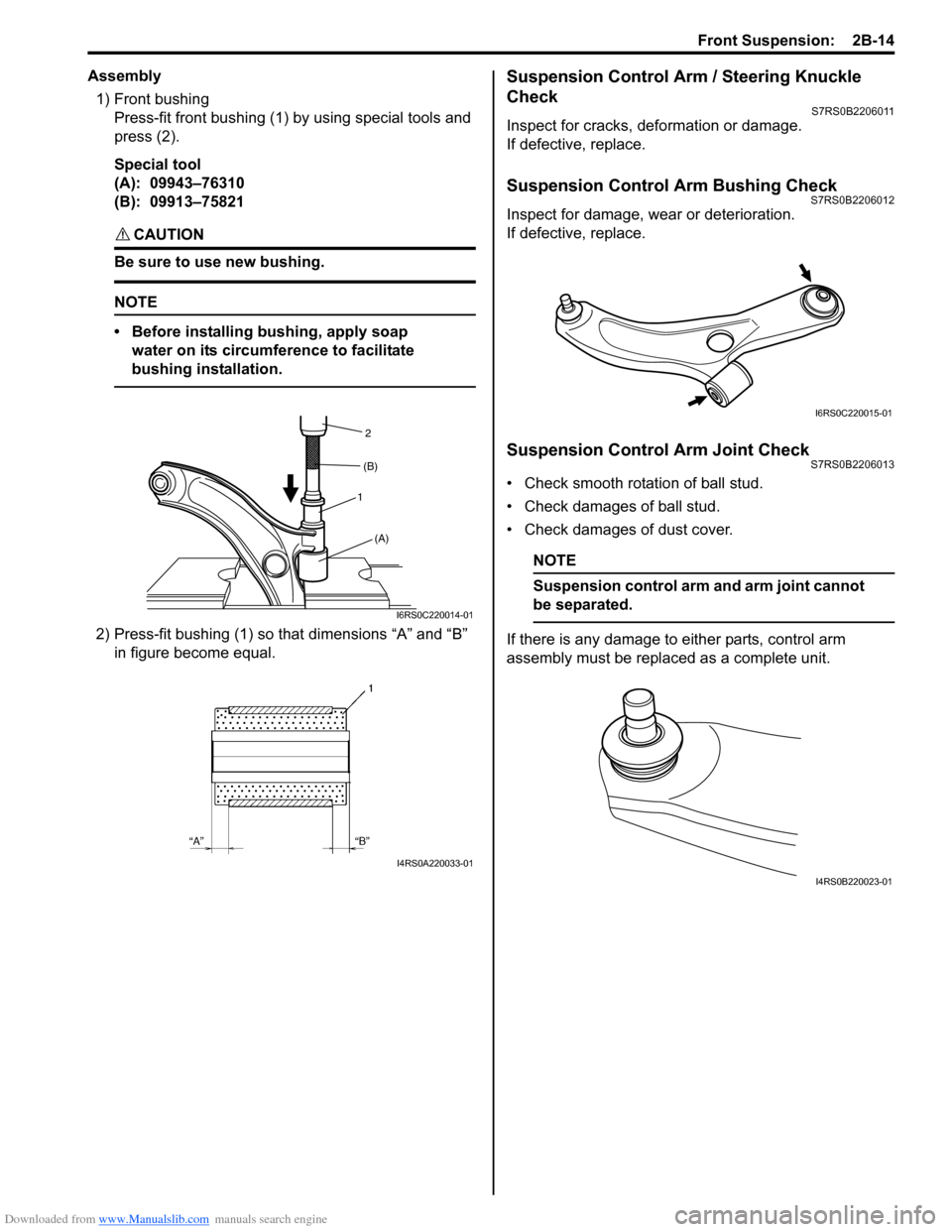
Assembly1) Front bushing Press-fit front bushing (1) by using special tools and
press (2).
Special tool
(A): 09943–76310
(B): 09913–75821
CAUTION!
Be sure to use new bushing.
NOTE
• Before installing bushing, apply soap water on its circumference to facilitate
bushing installation.
2) Press-fit bushing (1) so that dimensions “A” and “B” in figure become equal.
Suspension Control Arm / Steering Knuckle
Check
S7RS0B2206011
Inspect for cracks, deformation or damage.
If defective, replace.
Suspension Control Arm Bushing CheckS7RS0B2206012
Inspect for damage, wear or deterioration.
If defective, replace.
Suspension Control Arm Joint CheckS7RS0B2206013
• Check smooth rotation of ball stud.
• Check damages of ball stud.
• Check damages of dust cover.
NOTE
Suspension control a rm and arm joint cannot
be separated.
If there is any damage to either parts, control arm
assembly must be replaced as a complete unit.
1 2
(A)
(B)
I6RS0C220014-01
I4RS0A220033-01
I6RS0C220015-01
I4RS0B220023-01