2006 SUZUKI SWIFT Nut
[x] Cancel search: NutPage 697 of 1496
Downloaded from www.Manualslib.com manuals search engine Automatic Transmission/Transaxle: 5A-53
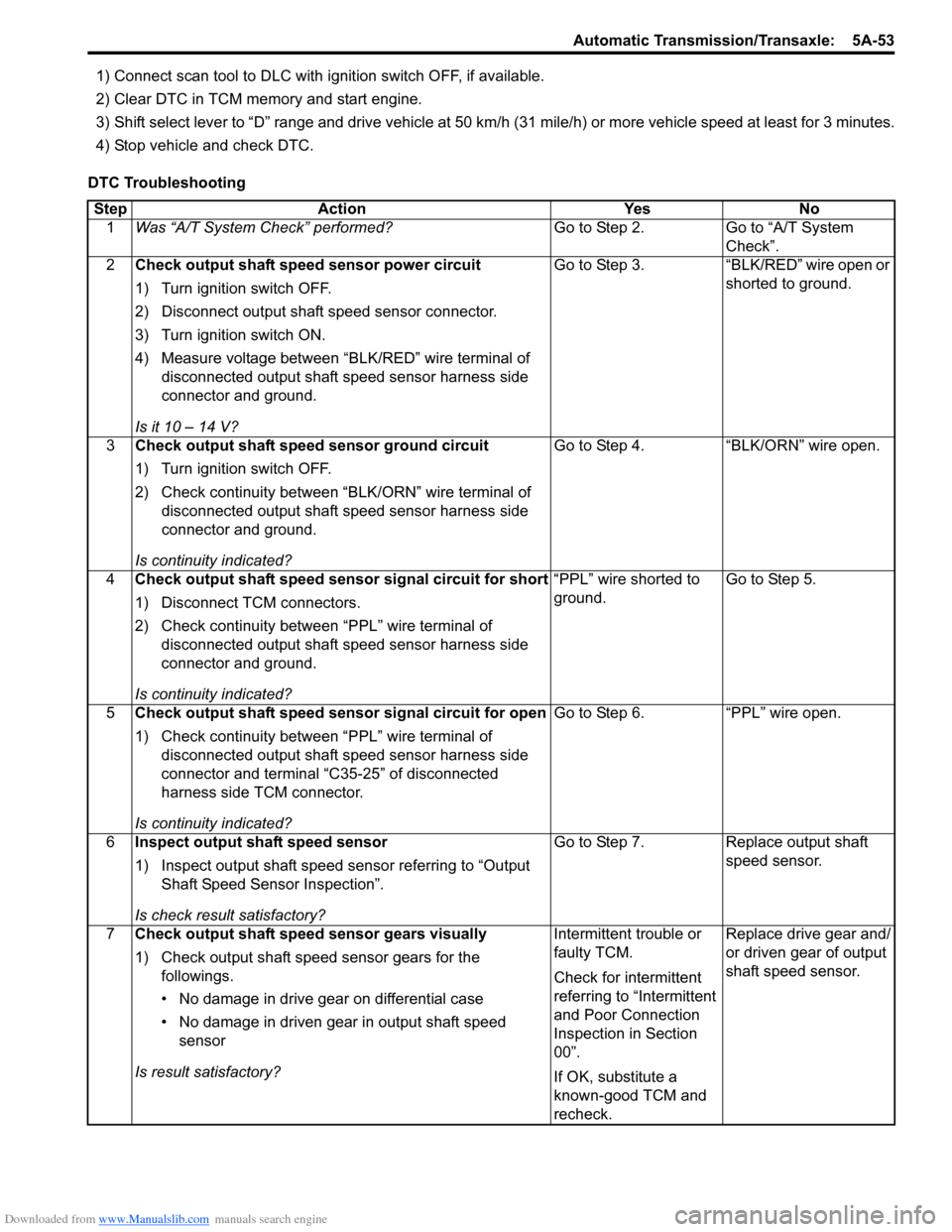
1) Connect scan tool to DLC with ignition switch OFF, if available.
2) Clear DTC in TCM memory and start engine.
3) Shift select lever to “D” range and drive vehicle at 50 km /h (31 mile/h) or more vehicle speed at least for 3 minutes.
4) Stop vehicle and check DTC.
DTC Troubleshooting Step Action Yes No 1 Was “A/T System Check” performed? Go to Step 2. Go to “A/T System
Check”.
2 Check output shaft speed sensor power circuit
1) Turn ignition switch OFF.
2) Disconnect output shaft speed sensor connector.
3) Turn ignition switch ON.
4) Measure voltage between “BLK/RED” wire terminal of
disconnected output shaft speed sensor harness side
connector and ground.
Is it 10 – 14 V? Go to Step 3. “BLK/RED” wire open or
shorted to ground.
3 Check output shaft speed sensor ground circuit
1) Turn ignition switch OFF.
2) Check continuity between “BLK/ORN” wire terminal of
disconnected output shaft speed sensor harness side
connector and ground.
Is continuity indicated? Go to Step 4. “BLK/ORN” wire open.
4 Check output shaft speed sensor signal circuit for short
1) Disconnect TCM connectors.
2) Check continuity between “PPL” wire terminal of
disconnected output shaft speed sensor harness side
connector and ground.
Is continuity indicated? “PPL” wire shorted to
ground.
Go to Step 5.
5 Check output shaft speed sensor signal circuit for open
1) Check continuity between “PPL” wire terminal of
disconnected output shaft speed sensor harness side
connector and terminal “C35-25” of disconnected
harness side TCM connector.
Is continuity indicated? Go to Step 6. “PPL” wire open.
6 Inspect output shaft speed sensor
1) Inspect output shaft speed sensor referring to “Output
Shaft Speed Sensor Inspection”.
Is check result satisfactory? Go to Step 7. Replace output shaft
speed sensor.
7 Check output shaft speed sensor gears visually
1) Check output shaft speed sensor gears for the
followings.
• No damage in drive gear on differential case
• No damage in driven gear in output shaft speed sensor
Is result satisfactory? Intermittent trouble or
faulty TCM.
Check for intermittent
referring to “Intermittent
and Poor Connection
Inspection in Section
00”.
If OK, substitute a
known-good TCM and
recheck.Replace drive gear and/
or driven gear of output
shaft speed sensor.
Page 749 of 1496
Downloaded from www.Manualslib.com manuals search engine Automatic Transmission/Transaxle: 5A-105
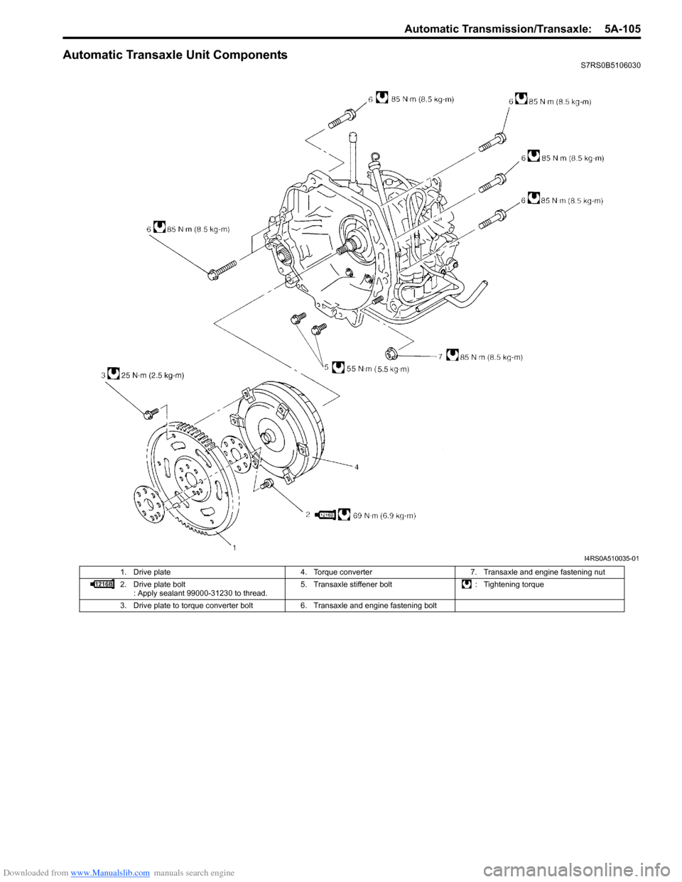
Automatic Transaxle Unit ComponentsS7RS0B5106030
I4RS0A510035-01
1. Drive plate4. Torque converter7. Transaxle and engine fastening nut
2. Drive plate bolt : Apply sealant 99000-31230 to thread. 5. Transaxle stiffener bolt
: Tightening torque
3. Drive plate to torque converter bolt 6. Transaxle and engine fastening bolt
Page 750 of 1496
Downloaded from www.Manualslib.com manuals search engine 5A-106 Automatic Transmission/Transaxle:
Automatic Transaxle Unit Dismounting and
Remounting
S7RS0B5106031
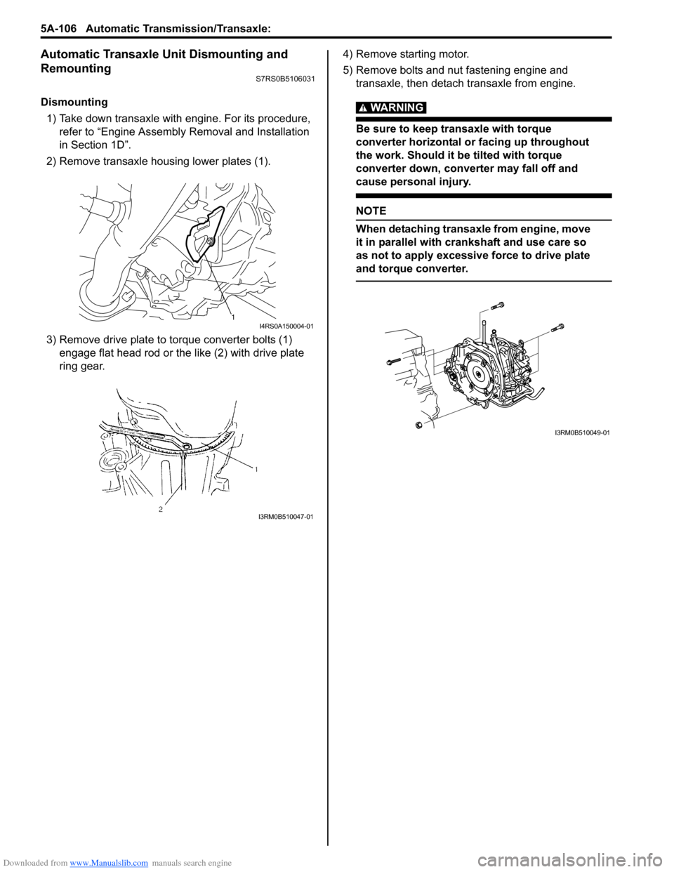
Dismounting1) Take down transaxle with engine. For its procedure, refer to “Engine Assembly Removal and Installation
in Section 1D”.
2) Remove transaxle housing lower plates (1).
3) Remove drive plate to torque converter bolts (1) engage flat head rod or the like (2) with drive plate
ring gear. 4) Remove starting motor.
5) Remove bolts and nut fastening engine and
transaxle, then detach transaxle from engine.WARNING!
Be sure to keep transaxle with torque
converter horizontal or facing up throughout
the work. Should it be tilted with torque
converter down, converter may fall off and
cause personal injury.
NOTE
When detaching transaxle from engine, move
it in parallel with cranks haft and use care so
as not to apply excessive force to drive plate
and torque converter.
1I4RS0A150004-01
I3RM0B510047-01
I3RM0B510049-01
Page 751 of 1496
Downloaded from www.Manualslib.com manuals search engine Automatic Transmission/Transaxle: 5A-107
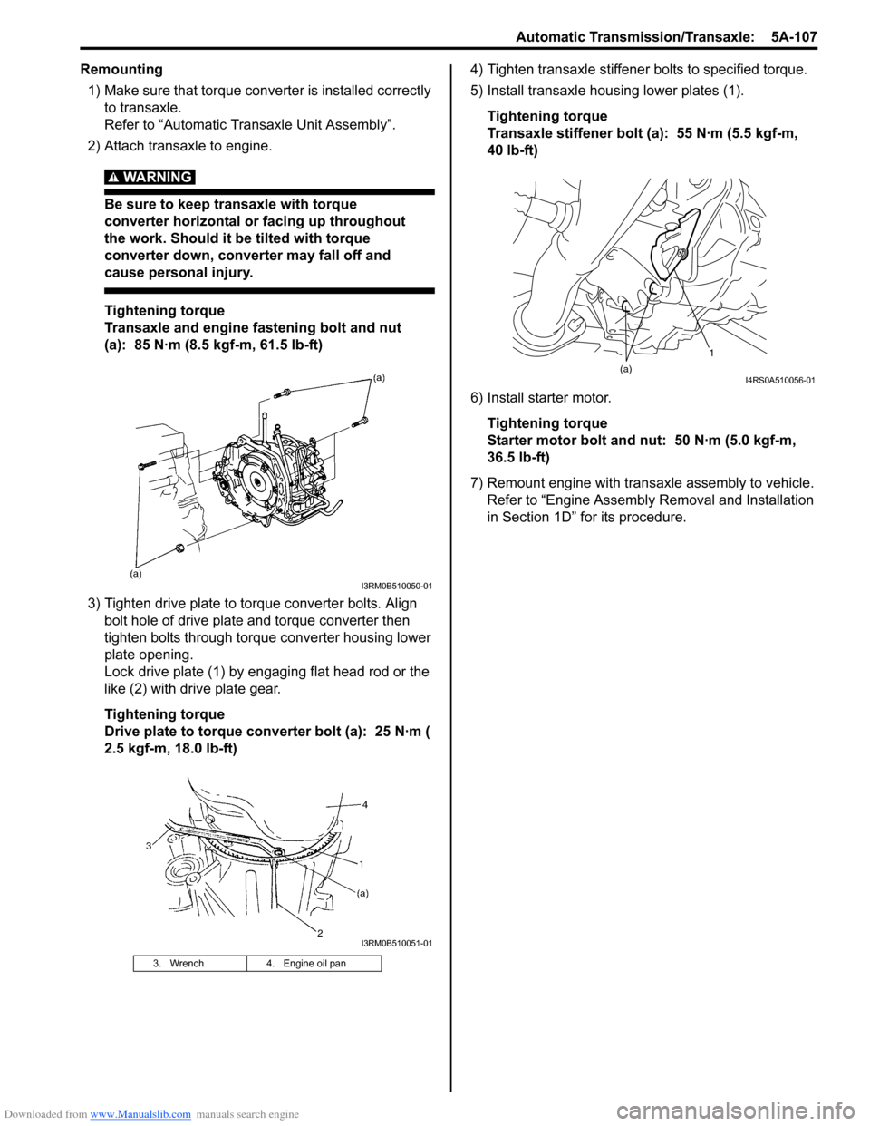
Remounting1) Make sure that torque converter is installed correctly to transaxle.
Refer to “Automatic Transaxle Unit Assembly”.
2) Attach transaxle to engine.
WARNING!
Be sure to keep transaxle with torque
converter horizontal or facing up throughout
the work. Should it be tilted with torque
converter down, converter may fall off and
cause personal injury.
Tightening torque
Transaxle and engine fastening bolt and nut
(a): 85 N·m (8.5 kgf-m, 61.5 lb-ft)
3) Tighten drive plate to torque converter bolts. Align bolt hole of drive plate and torque converter then
tighten bolts through torque converter housing lower
plate opening.
Lock drive plate (1) by engaging flat head rod or the
like (2) with drive plate gear.
Tightening torque
Drive plate to torque converter bolt (a): 25 N·m (
2.5 kgf-m, 18.0 lb-ft) 4) Tighten transaxle stiffener bolts to specified torque.
5) Install transaxle housing lower plates (1).
Tightening torque
Transaxle stiffener bolt (a): 55 N·m (5.5 kgf-m,
40 lb-ft)
6) Install starter motor. Tightening torque
Starter motor bolt and nut: 50 N·m (5.0 kgf-m,
36.5 lb-ft)
7) Remount engine with transaxle assembly to vehicle. Refer to “Engine Assembly Removal and Installation
in Section 1D” for its procedure.
3. Wrench 4. Engine oil pan
I3RM0B510050-01
I3RM0B510051-01
1
(a)
I4RS0A510056-01
Page 753 of 1496
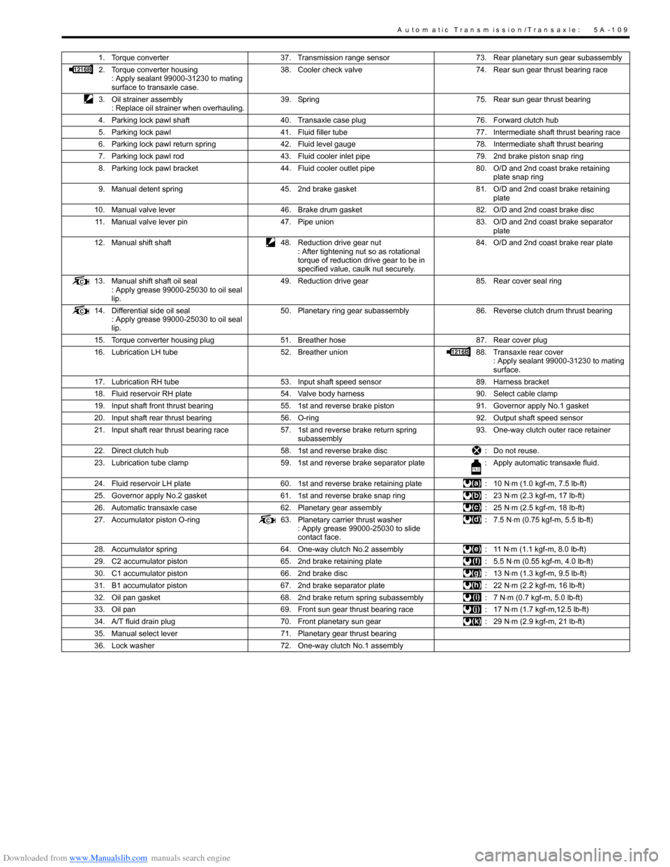
Downloaded from www.Manualslib.com manuals search engine A u to m a tic Tra n s m is s io n /Tra n s a x le : 5 A -1 0 9
1. Torque converter37. Transmission range sensor 73. Rear planetary sun gear subassembly
2. Torque converter housing : Apply sealant 99000-31230 to mating
surface to transaxle case. 38. Cooler check valve
74. Rear sun gear thrust bearing race
3. Oil strainer assembly : Replace oil strainer when overhauling. 39. Spring
75. Rear sun gear thrust bearing
4. Parking lock pawl shaft 40. Transaxle case plug 76. Forward clutch hub
5. Parking lock pawl 41. Fluid filler tube 77. Intermediate shaft thrust bearing race
6. Parking lock pawl return spring 42. Fluid level gauge 78. Intermediate shaft thrust bearing
7. Parking lock pawl rod 43. Fluid cooler inlet pipe 79. 2nd brake piston snap ring
8. Parking lock pawl bracket 44. Fluid cooler outlet pipe 80. O/D and 2nd coast brake retaining
plate snap ring
9. Manual detent spring 45. 2nd brake gasket 81. O/D and 2nd coast brake retaining
plate
10. Manual valve lever 46. Brake drum gasket 82. O/D and 2nd coast brake disc
11. Manual valve lever pin 47. Pipe union 83. O/D and 2nd coast brake separator
plate
12. Manual shift shaft 48. Reduction drive gear nut
: After tightening nut so as rotational
torque of reduction drive gear to be in
specified value, caulk nut securely. 84. O/D and 2nd coast brake rear plate
13. Manual shift shaft oil seal : Apply grease 99000-25030 to oil seal
lip. 49. Reduction drive gear
85. Rear cover seal ring
14. Differential side oil seal : Apply grease 99000-25030 to oil seal
lip. 50. Planetary ring gear subassembly
86. Reverse clutch drum thrust bearing
15. Torque converter housing plug 51. Breather hose 87. Rear cover plug
16. Lubrication LH tube 52. Breather union 88. Transaxle rear cover
: Apply sealant 99000-31230 to mating
surface.
17. Lubrication RH tube 53. Input shaft speed sensor 89. Harness bracket
18. Fluid reservoir RH plate 54. Valve body harness 90. Select cable clamp
19. Input shaft front thrust bearing 55. 1st and reverse brake piston 91. Governor apply No.1 gasket
20. Input shaft rear thrust bearing 56. O-ring 92. Output shaft speed sensor
21. Input shaft rear thrust bearing race 57. 1st and reverse brake return spring
subassembly 93. One-way clutch outer race retainer
22. Direct clutch hub 58. 1st and reverse brake disc : Do not reuse.
23. Lubrication tube clamp 59. 1st and reverse brake separator plate : Apply automatic transaxle fluid.
24. Fluid reservoir LH plate 60. 1st and reverse brake retaining plate : 10 N⋅m (1.0 kgf-m, 7.5 lb-ft)
25. Governor apply No.2 gasket 61. 1st and reverse brake snap ring : 23 N⋅m (2.3 kgf-m, 17 lb-ft)
26. Automatic transaxle case 62. Planetary gear assembly : 25 N⋅m (2.5 kgf-m, 18 lb-ft)
27. Accumulator piston O-ring 63. Planetary carrier thrust washer
: Apply grease 99000-25030 to slide
contact face. : 7.5 N
⋅m (0.75 kgf-m, 5.5 lb-ft)
28. Accumulator spring 64. One-way clutch No.2 assembly : 11 N⋅m (1.1 kgf-m, 8.0 lb-ft)
29. C2 accumulator piston 65. 2nd brake retaining plate : 5.5 N⋅m (0.55 kgf-m, 4.0 lb-ft)
30. C1 accumulator piston 66. 2nd brake disc : 13 N⋅m (1.3 kgf-m, 9.5 lb-ft)
31. B1 accumulator piston 67. 2nd brake separator plate : 22 N⋅m (2.2 kgf-m, 16 lb-ft)
32. Oil pan gasket 68. 2nd brake return spring subassembly : 7 N⋅m (0.7 kgf-m, 5.0 lb-ft)
33. Oil pan 69. Front sun gear thrust bearing race : 17 N⋅m (1.7 kgf-m,12.5 lb-ft)
34. A/T fluid drain plug 70. Front planetary sun gear : 29 N⋅m (2.9 kgf-m, 21 lb-ft)
35. Manual select lever 71. Planetary gear thrust bearing
36. Lock washer 72. One-way clutch No.1 assembly
Page 754 of 1496
Downloaded from www.Manualslib.com manuals search engine 5A-110 Automatic Transmission/Transaxle:
Automatic Transaxle Unit DisassemblyS7RS0B5106033
CAUTION!
• Thoroughly clean transaxle exterior before overhauling it.
• Keep working table, tools and hands clean while overhauling.
• Use special care to handle aluminum parts so as not to damage them.
• Do not expose removed parts to dust. Keep them always clean.
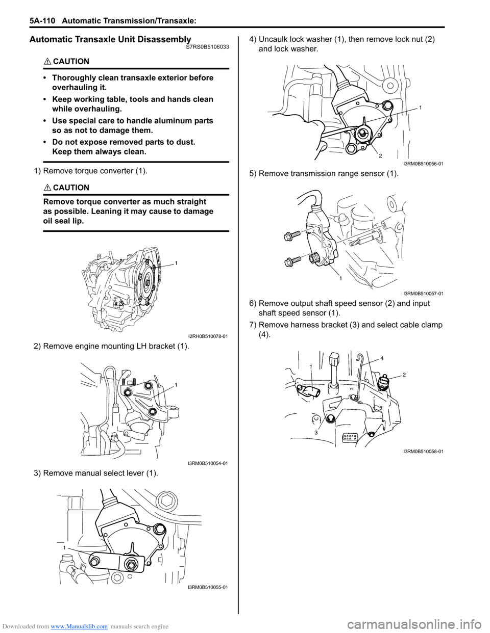
1) Remove torque converter (1).
CAUTION!
Remove torque converte r as much straight
as possible. Leaning it may cause to damage
oil seal lip.
2) Remove engine mounting LH bracket (1).
3) Remove manual select lever (1). 4) Uncaulk lock washer (1),
then remove lock nut (2)
and lock washer.
5) Remove transmission range sensor (1).
6) Remove output shaft speed sensor (2) and input shaft speed sensor (1).
7) Remove harness bracket (3) and select cable clamp (4).
I2RH0B510078-01
I3RM0B510054-01
1
I3RM0B510055-01
1
2
I3RM0B510056-01
I3RM0B510057-01
I3RM0B510058-01
Page 763 of 1496

Downloaded from www.Manualslib.com manuals search engine Automatic Transmission/Transaxle: 5A-119
60) Remove snap ring while the 1st and reverse brake piston return springs are compressed using special
tool and hydraulic press.
CAUTION!
Do not press 1st and reverse brake return
spring subassembly in over 0.8 mm (0.031
in.).
Excessive compression may cause damage
to return spring subassembly, discs, plates
and/or piston.
Special tool
(A): 09926–97620
61) Remove 1st and reverse brake retaining plate, discs and separator plates.
62) Remove 1st and reverse brake return spring subassembly (1).
63) Turn over transaxle and uncaulk reduction drive gear nut (1). 64) Secure reduction drive gear (1) with parking lock
pawl, then remove reduction drive gear nut.
CAUTION!
• It is recommended that this operation should be carried out on rubber mat to
prevent damaging transaxle case.
• Never reuse removed nut.
65) Using special tools and hydraulic press, remove planetary ring gear subassembly (1).
CAUTION!
Do not reuse planetary ring gear
subassembly. Otherwise it may cause
damage to planetary gear unit and/or
reduction gears.
Special tool
(A): 09913–84510
(B): 09923–78210
66) Remove parking lock pawl shaft, then spring (2) and parking lock pawl (1).
I2RH0B510134-01
I2RH0B510135-01
I2RH0B510136-01
I2RH0B510137-02
I2RH0B510138-01
I2RH0B510139-01
Page 794 of 1496
Downloaded from www.Manualslib.com manuals search engine 5A-150 Automatic Transmission/Transaxle:
Automatic Transaxle Unit AssemblyS7RS0B5106060
CAUTION!
• Automatic transaxle consists of highly precise parts. As even flaw in small part
may cause oil leakage or decrease in
function, check each part carefully before
installation.
• Clean all parts with compressed air. Never use wiping cloths or rags.
• Before assembling new clutch or brake discs, soak them in automatic transaxle
fluid for at least 2 hours.
• Be sure to use new gaskets and O-rings.
• Lubricate O-rings with automatic transaxle
fluid.
• Apply automatic transaxle fluid on sliding or rotating surfaces of the parts before
assembly.
• Use Suzuki Super Grease “C” to retain parts in place.
• Be sure to install thrust bearings and races in correct direction and position.
• Make sure that snap ring ends are not aligned with one of cut outs and are
installed in groove correctly.
• Do not use adhesive cements on gaskets and similar parts.
• Be sure to torque each bolt and nut to specification.
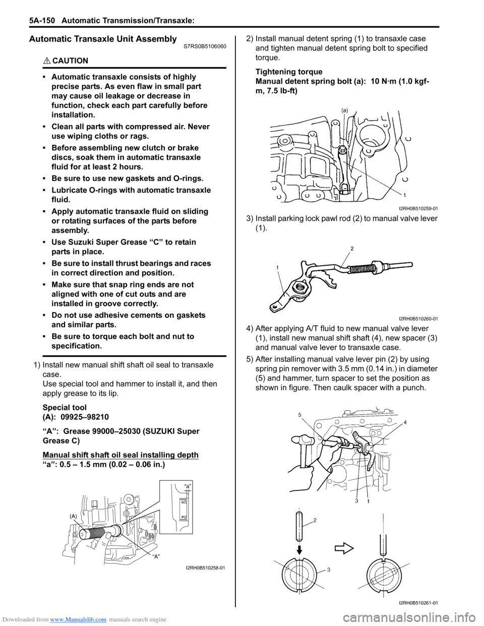
1) Install new manual shift sh aft oil seal to transaxle
case.
Use special tool and hammer to install it, and then
apply grease to its lip.
Special tool
(A): 09925–98210
“A”: Grease 99000–25030 (SUZUKI Super
Grease C)
Manual shift shaft oil seal installing depth
“a”: 0.5 – 1.5 mm (0.02 – 0.06 in.) 2) Install manual detent spring (1) to transaxle case
and tighten manual detent spring bolt to specified
torque.
Tightening torque
Manual detent spring bolt (a): 10 N·m (1.0 kgf-
m, 7.5 lb-ft)
3) Install parking lock pawl ro d (2) to manual valve lever
(1).
4) After applying A/T fluid to new manual valve lever (1), install new manual shift shaft (4), new spacer (3)
and manual valve lever to transaxle case.
5) After installing manual valve lever pin (2) by using spring pin remover with 3.5 mm (0.14 in.) in diameter
(5) and hammer, turn spacer to set the position as
shown in figure. Then caulk spacer with a punch.
“a”
(A)
“A”
I2RH0B510258-01
I2RH0B510259-01
I2RH0B510260-01
I2RH0B510261-01