2006 SUZUKI SWIFT power steering
[x] Cancel search: power steeringPage 1461 of 1496

Downloaded from www.Manualslib.com manuals search engine Immobilizer Control System: 10C-18
Repair Instructions
Immobilizer Control Module (ICM) Removal and
Installation
S7RS0BA306001
Removal1) Disconnect negative (–) cable at battery.
2) Remove steering wheel referring to “Steering Wheel Removal and Installa tion in Section 6B”.
3) Remove steering column lower and upper covers.
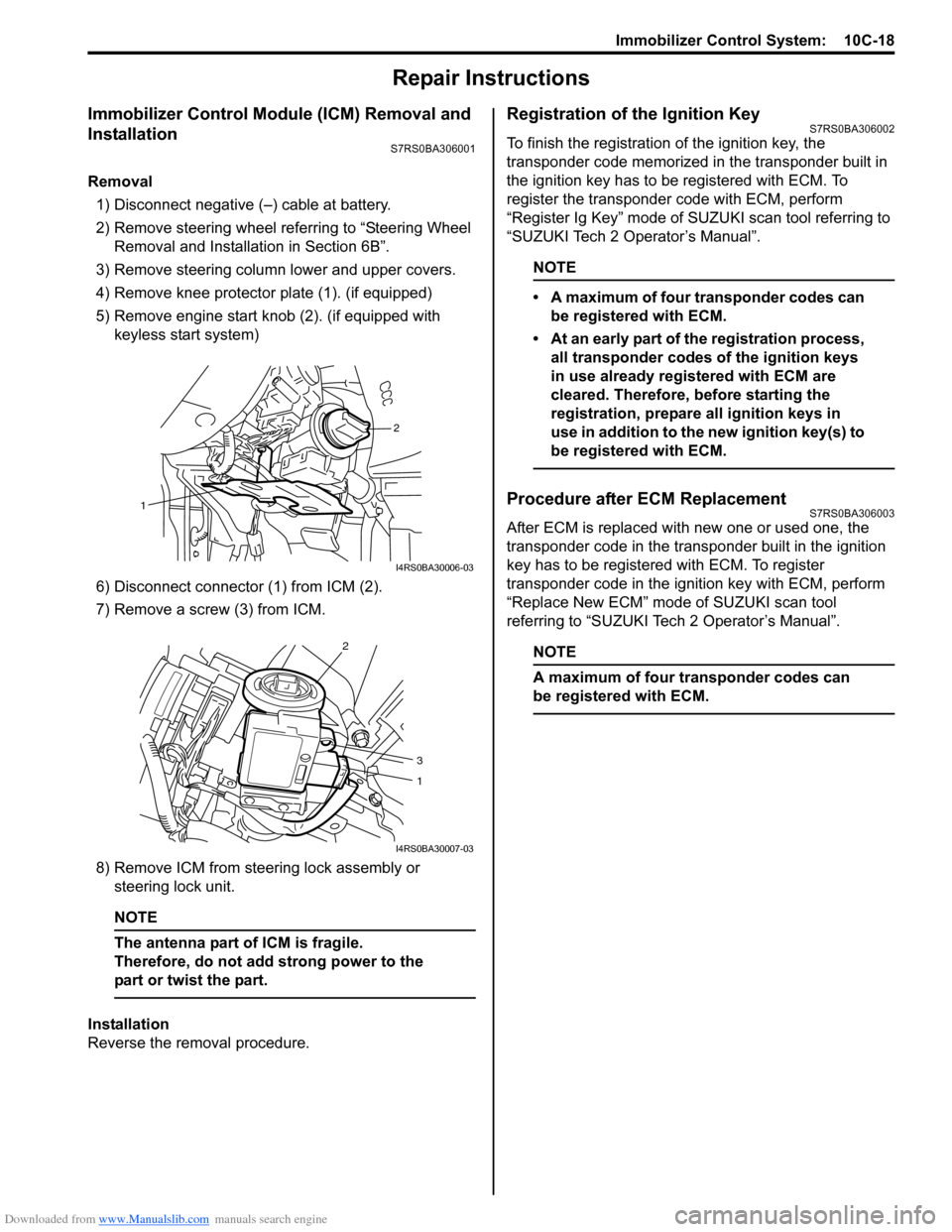
4) Remove knee protector plate (1). (if equipped)
5) Remove engine start knob (2). (if equipped with keyless start system)
6) Disconnect connector (1) from ICM (2).
7) Remove a screw (3) from ICM.
8) Remove ICM from steering lock assembly or steering lock unit.
NOTE
The antenna part of ICM is fragile.
Therefore, do not add strong power to the
part or twist the part.
Installation
Reverse the removal procedure.
Registration of the Ignition KeyS7RS0BA306002
To finish the registration of the ignition key, the
transponder code memorized in the transponder built in
the ignition key has to be registered with ECM. To
register the transponder code with ECM, perform
“Register Ig Key” mode of SU ZUKI scan tool referring to
“SUZUKI Tech 2 Operator’s Manual”.
NOTE
• A maximum of four transponder codes can be registered with ECM.
• At an early part of the registration process, all transponder codes of the ignition keys
in use already registered with ECM are
cleared. Therefore, before starting the
registration, prepare all ignition keys in
use in addition to the new ignition key(s) to
be registered with ECM.
Procedure after ECM ReplacementS7RS0BA306003
After ECM is replaced with new one or used one, the
transponder code in the transponder built in the ignition
key has to be registered with ECM. To register
transponder code in the ignition key with ECM, perform
“Replace New ECM” mode of SUZUKI scan tool
referring to “SUZUKI Tech 2 Operator’s Manual”.
NOTE
A maximum of four transponder codes can
be registered with ECM.
2
1
I4RS0BA30006-03
2
3
1
I4RS0BA30007-03
Page 1477 of 1496

Downloaded from www.Manualslib.com manuals search engine Keyless Start System: 10E-15
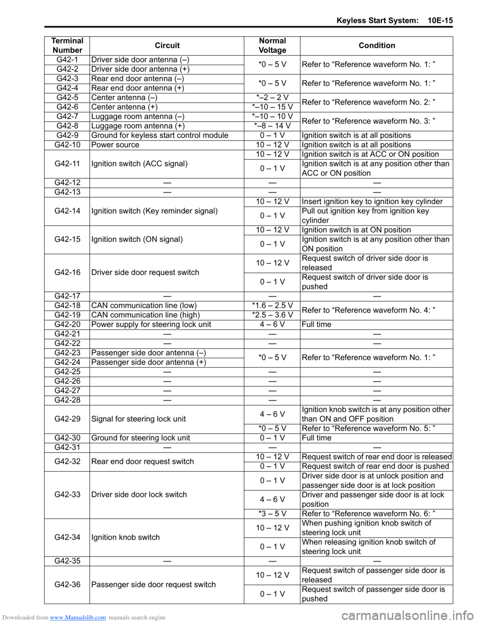
Terminal Number Circuit Normal
Vo l ta g e Condition
G42-1 Driver side door antenna (–) *0 – 5 V Refer to “Reference waveform No. 1: ”
G42-2 Driver side door antenna (+)
G42-3 Rear end door antenna (–) *0 – 5 V Refer to “Reference waveform No. 1: ”
G42-4 Rear end door antenna (+)
G42-5 Center antenna (–) *–2 – 2 V Refer to “Reference waveform No. 2: ”
G42-6 Center antenna (+) *–10 – 15 V
G42-7 Luggage room antenna (–) *–10 – 10 V Refer to “Reference waveform No. 3: ”
G42-8 Luggage room antenna (+) *–8 – 14 V
G42-9 Ground for keyless start control module 0 – 1 V Ignition switch is at all positions
G42-10 Power source 10 – 12 V Ignition switch is at all positions
G42-11 Ignition switch (ACC signal) 10 – 12 V Ignition switch is at ACC or ON position
0 – 1 V Ignition switch is at any position other than
ACC or ON position
G42-12 — — —
G42-13 — — —
G42-14 Ignition switch (Key reminder signal) 10 – 12 V Insert ignition key to ignition key cylinder
0 – 1 V Pull out ignition key from ignition key
cylinder
G42-15 Ignition switch (ON signal) 10 – 12 V Ignition switch is at ON position
0 – 1 V Ignition switch is at any position other than
ON position
G42-16 Driver side door request switch 10 – 12 V
Request switch of driver side door is
released
0 – 1 V Request switch of driver side door is
pushed
G42-17 — — —
G42-18 CAN communication line (low) *1.6 – 2.5 V Refer to “Reference waveform No. 4: ”
G42-19 CAN communication line (high) *2.5 – 3.6 V
G42-20 Power supply for steering lock unit 4 – 6 V Full time
G42-21 — — —
G42-22 — — —
G42-23 Passenger side door antenna (–) *0 – 5 V Refer to “Reference waveform No. 1: ”
G42-24 Passenger side door antenna (+)
G42-25 — — —
G42-26 — — —
G42-27 — — —
G42-28 — — —
G42-29 Signal for steering lock unit 4 – 6 VIgnition knob switch is at any position other
than ON and OFF position
*0 – 5 V Refer to “Reference waveform No. 5: ”
G42-30 Ground for steering lock unit 0 – 1 V Full time
G42-31 — — —
G42-32 Rear end door request switch 10 – 12 V Request switch of rear end door is released
0 – 1 V Request switch of rear end door is pushed
G42-33 Driver side door lock switch 0 – 1 V
Driver side door is at unlock position and
passenger side door is at lock position
4 – 6 V Driver and passenger side door is at lock
position
*3 – 5 V Refer to “Reference waveform No. 6: ”
G42-34 Ignition knob switch 10 – 12 V
When pushing ignition knob switch of
steering lock unit
0 – 1 V When releasing ignition knob switch of
steering lock unit
G42-35 — — —
G42-36 Passenger side door request switch 10 – 12 V
Request switch of passenger side door is
released
0 – 1 V Request switch of passenger side door is
pushed
Page 1483 of 1496

Downloaded from www.Manualslib.com manuals search engine Keyless Start System: 10E-21
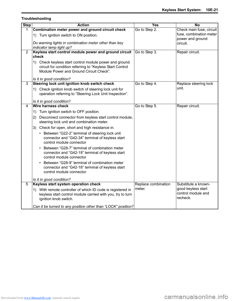
TroubleshootingStep Action Yes No 1 Combination meter power and ground circuit check
1) Turn ignition switch to ON position.
Do warning lights in combi nation meter other than key
indicator lamp light up? Go to Step 2. Check main fuse, circuit
fuse, combination meter
power and ground
circuit.
2 Keyless start control module power and ground circuit
check
1) Check keyless start control module power and ground
circuit for condition referrin g to “Keyless Start Control
Module Power and Ground Circuit Check”.
Is it in good condition? Go to Step 3. Repair circuit.
3 Steering lock unit ignition knob switch check
1) Check ignition knob switch of steering lock unit for
operation referring to “Steering Lock Unit Inspection”.
Is it in good condition? Go to Step 4. Replace steering lock
unit.
4 Wire harness check
1) Turn ignition switch to OFF position.
2) Disconnect connector from ke yless start control module,
steering lock unit and combination meter.
3) Check for open, short and high resistance in. • Between “G22-2” terminal of steering lock unit connector and “G42-34” terminal of keyless start
control module connector
• Between “G28-7” terminal of combination meter connector and “G42-19” terminal of keyless start
control module connector
• Between “G28-9” terminal of combination meter connector and “G42-18” terminal of keyless start
control module connector
Is it in good condition? Go to Step 5. Repair circuit.
5 Keyless start system operation check
1) With remote controller of which ID code is registered in
keyless start control module carried with you, try to turn
ignition knob switch.
Can it be turned to any position other than “LOCK” position? Replace combination
meter.
Substitute a known-
good keyless start
control module and
recheck.
Page 1486 of 1496

Downloaded from www.Manualslib.com manuals search engine 10E-24 Keyless Start System:
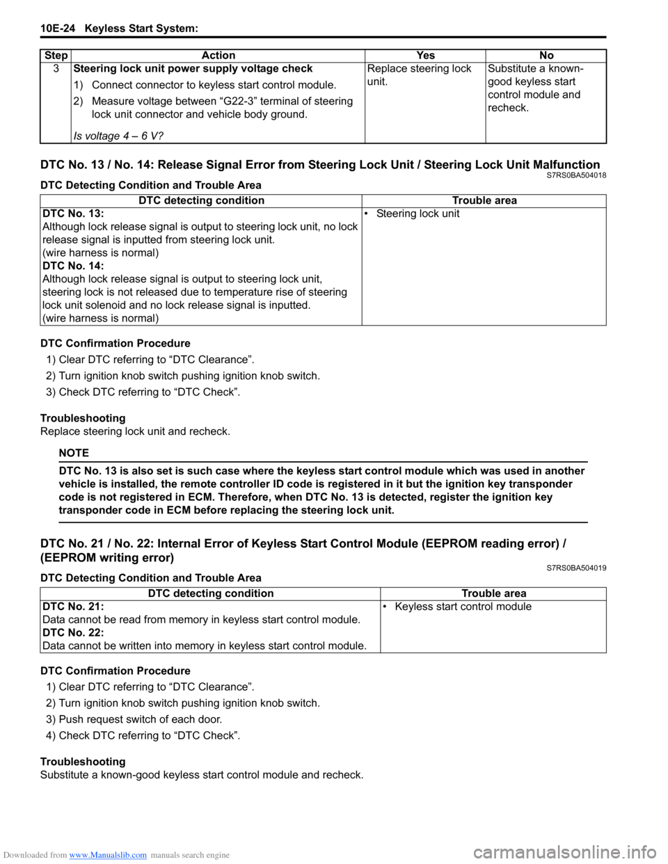
DTC No. 13 / No. 14: Release Signal Error from Steering Lock Unit / Steering Lock Unit MalfunctionS7RS0BA504018
DTC Detecting Condition and Trouble Area
DTC Confirmation Procedure1) Clear DTC referring to “DTC Clearance”.
2) Turn ignition knob switch pushing ignition knob switch.
3) Check DTC referring to “DTC Check”.
Troubleshooting
Replace steering lock unit and recheck.
NOTE
DTC No. 13 is also set is such case where the keyless start control module which was used in another
vehicle is installed, the remote controller ID code is registered in it but the ignition key transponder
code is not registered in ECM. Therefore, when DTC No. 13 is detected, register the ignition key
transponder code in ECM before replacing the steering lock unit.
DTC No. 21 / No. 22: Internal Error of Keyle ss Start Control Module (EEPROM reading error) /
(EEPROM writing error)
S7RS0BA504019
DTC Detecting Condition and Trouble Area
DTC Confirmation Procedure
1) Clear DTC referring to “DTC Clearance”.
2) Turn ignition knob switch pushing ignition knob switch.
3) Push request switch of each door.
4) Check DTC referring to “DTC Check”.
Troubleshooting
Substitute a known-good keyless start control module and recheck. 3
Steering lock unit power supply voltage check
1) Connect connector to keyl ess start control module.
2) Measure voltage between “G22-3” terminal of steering lock unit connector and vehicle body ground.
Is voltage 4 – 6 V? Replace steering lock
unit.
Substitute a known-
good keyless start
control module and
recheck.
Step Action Yes No
DTC detecting condition
Trouble area
DTC No. 13:
Although lock release signal is ou tput to steering lock unit, no lock
release signal is inputted from steering lock unit.
(wire harness is normal)
DTC No. 14:
Although lock release signal is output to steering lock unit,
steering lock is not released due to temperature rise of steering
lock unit solenoid and no lock release signal is inputted.
(wire harness is normal) • Steering lock unit
DTC detecting condition Trouble area
DTC No. 21:
Data cannot be read from memory in keyless start control module.
DTC No. 22:
Data cannot be written into memory in keyless start control module.• Keyless start control module