2006 SUZUKI SWIFT Temp sensor
[x] Cancel search: Temp sensorPage 783 of 1496

Downloaded from www.Manualslib.com manuals search engine Automatic Transmission/Transaxle: 5A-139
2) Install reduction driven gear (1) with special tools and hydraulic press.
Special tool
(A): 09913–84510
(B): 09925–88210 3) Install countershaft LH bearing (1) with special tools
and hydraulic press.
Special tool
(A): 09913–84510
(B): 09925–88210
Valve Body Assembly ComponentsS7RS0B5106052
I2RH0B510213-01
I2RH0B510214-01
I4RS0A510044-01
1. Pressure control solenoid valve 6. Temperature sensor clamp : Apply automatic transaxle fluid.
2. Shift solenoid valve-A (No.1) 7. Valve body assembly: 11 N⋅m (1.1 kgf-m, 8.0 lb-ft)
3. Shift solenoid valve-B (No.2) 8. Manual valve: Do not reuse.
4. TCC pressure control solenoid valve 9. Solenoid lock plate
5. Timing solenoid valve 10. O-ring
Page 784 of 1496

Downloaded from www.Manualslib.com manuals search engine 5A-140 Automatic Transmission/Transaxle:
Valve Body Assembly Disassembly and
Reassembly
S7RS0B5106053
CAUTION!
When replacing pressure control solenoid
valve and/or TCC pressure control solenoid
valve, it is strictly required to replace it
together with valve body assembly as a set.
Replacing pressure control solenoid valve
and/or TCC pressure control solenoid valve
independently may cause excessive shift
shock.
Disassembly1) Pull out manual valve (1).
2) Remove pressure cont rol solenoid valve (1).
3) Remove TCC pressure control solenoid valve (1). 4) Remove shift solenoid valve-A (1).
5) Remove shift solenoid valve-B (1).
6) Remove timing solenoid valve (1).
7) Remove temperature sensor clamp (1).
2. Solenoid lock plate
I2RH0B510216-01
I2RH0B510217-01
1
I4RS0A510045-01
I2RH0B510219-01
I2RH0B510220-01
I2RH0B510221-01
I2RH0B510222-01
Page 807 of 1496

Downloaded from www.Manualslib.com manuals search engine Automatic Transmission/Transaxle: 5A-163
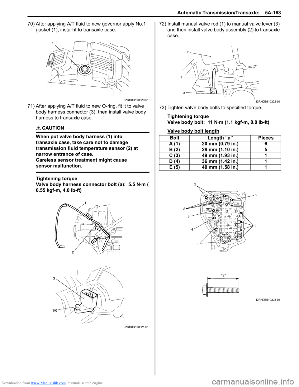
70) After applying A/T fluid to new governor apply No.1 gasket (1), install it to transaxle case.
71) After applying A/T fluid to new O-ring, fit it to valve body harness connector (3), then install valve body
harness to transaxle case.
CAUTION!
When put valve body harness (1) into
transaxle case, take care not to damage
transmission fluid temperature sensor (2) at
narrow entrance of case.
Careless sensor treatment might cause
sensor malfunction.
Tightening torque
Valve body harness connector bolt (a): 5.5 N·m (
0.55 kgf-m, 4.0 lb-ft) 72) Install manual valve rod (1) to manual valve lever (3)
and then install valve body assembly (2) to transaxle
case.
73) Tighten valve body bolts to specified torque. Tightening torque
Valve body bolt: 11 N·m (1.1 kgf-m, 8.0 lb-ft)
Valve body bolt length
I2RH0B510320-01
I2RH0B510321-01
Bolt Length “a” Pieces
A (1) 20 mm (0.79 in.) 6
B (2) 28 mm (1.10 in.) 5
C (3) 49 mm (1.93 in.) 1
D (4) 36 mm (1.42 in.) 1
E (5) 40 mm (1.58 in.) 1
I2RH0B510322-01
I2RH0B510323-01
Page 808 of 1496

Downloaded from www.Manualslib.com manuals search engine 5A-164 Automatic Transmission/Transaxle:
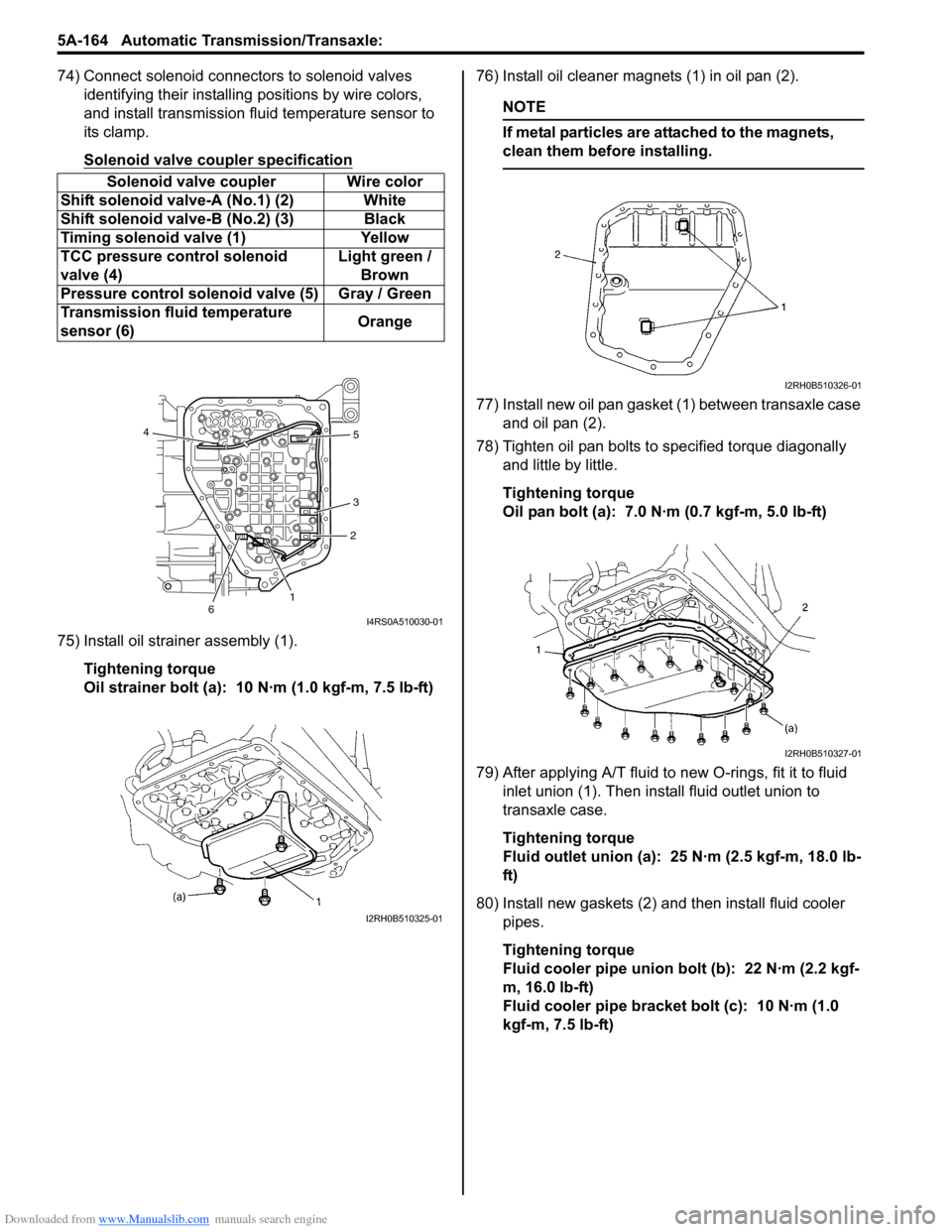
74) Connect solenoid connectors to solenoid valves identifying their installing positions by wire colors,
and install transmission fluid temperature sensor to
its clamp.
Solenoid valve coupler specification
75) Install oil strainer assembly (1).
Tightening torque
Oil strainer bolt (a): 10 N·m (1.0 kgf-m, 7.5 lb-ft) 76) Install oil cleaner magnets (1) in oil pan (2).
NOTE
If metal particles are attached to the magnets,
clean them before installing.
77) Install new oil pan gasket (1) between transaxle case
and oil pan (2).
78) Tighten oil pan bolts to specified torque diagonally and little by little.
Tightening torque
Oil pan bolt (a): 7.0 N·m (0.7 kgf-m, 5.0 lb-ft)
79) After applying A/T fluid to new O-rings, fit it to fluid inlet union (1). Then inst all fluid outlet union to
transaxle case.
Tightening torque
Fluid outlet union (a): 25 N·m (2.5 kgf-m, 18.0 lb-
ft)
80) Install new gaskets (2) and then install fluid cooler pipes.
Tightening torque
Fluid cooler pipe union bolt (b): 22 N·m (2.2 kgf-
m, 16.0 lb-ft)
Fluid cooler pipe bracket bolt (c): 10 N·m (1.0
kgf-m, 7.5 lb-ft)
Solenoid valve coupler Wire color
Shift solenoid valve-A (No.1) (2) White
Shift solenoid val ve-B (No.2) (3) Black
Timing solenoid valve (1) Yellow
TCC pressure control solenoid
valve (4) Light green /
Brown
Pressure control solenoid valve (5) Gray / Green
Transmission fluid temperature
sensor (6) Orange
12
3 5
4
6
I4RS0A510030-01
I2RH0B510325-01
I2RH0B510326-01
I2RH0B510327-01
Page 809 of 1496

Downloaded from www.Manualslib.com manuals search engine Automatic Transmission/Transaxle: 5A-165
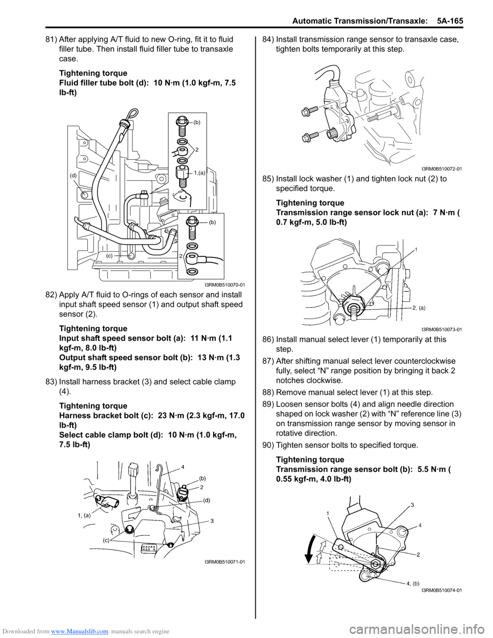
81) After applying A/T fluid to new O-ring, fit it to fluid filler tube. Then install fl uid filler tube to transaxle
case.
Tightening torque
Fluid filler tube bolt (d): 10 N·m (1.0 kgf-m, 7.5
lb-ft)
82) Apply A/T fluid to O-rings of each sensor and install input shaft speed sensor (1) and output shaft speed
sensor (2).
Tightening torque
Input shaft speed sensor bolt (a): 11 N·m (1.1
kgf-m, 8.0 lb-ft)
Output shaft speed sensor bolt (b): 13 N·m (1.3
kgf-m, 9.5 lb-ft)
83) Install harness bracket (3) and select cable clamp (4).
Tightening torque
Harness bracket bolt (c): 23 N·m (2.3 kgf-m, 17.0
lb-ft)
Select cable clamp bolt (d): 10 N·m (1.0 kgf-m,
7.5 lb-ft) 84) Install transmission range sensor to transaxle case,
tighten bolts temporarily at this step.
85) Install lock washer (1) and tighten lock nut (2) to specified torque.
Tightening torque
Transmission range sensor lock nut (a): 7 N·m (
0.7 kgf-m, 5.0 lb-ft)
86) Install manual select leve r (1) temporarily at this
step.
87) After shifting manual se lect lever counterclockwise
fully, select “N” range position by bringing it back 2
notches clockwise.
88) Remove manual select lever (1) at this step.
89) Loosen sensor bolts (4) and align needle direction shaped on lock washer (2) with “N” reference line (3)
on transmission range sensor by moving sensor in
rotative direction.
90) Tighten sensor bolts to specified torque.
Tightening torque
Transmission range sensor bolt (b): 5.5 N·m (
0.55 kgf-m, 4.0 lb-ft)
(c)
(d)
(b)
2
1,(a)
(b)
2
I3RM0B510070-01
I3RM0B510071-01
I3RM0B510072-01
I3RM0B510073-01
I3RM0B510074-01
Page 890 of 1496

Downloaded from www.Manualslib.com manuals search engine 6C-8 Power Assisted Steering System:
Step 2: DTC Check, Record and Clearance
First, check DTC, referring to “DTC Check”. If DTC is
indicated, print it or write them down and then clear them
by referring to “DTC Clearance”. DTC indicates
malfunction that occurred in the system but does not
indicate whether it exists now or it occurred in the past
and the normal condition has been restored now. To
check which case applies, check the symptom in
question according to Step 5 and recheck DTC
according to Step 6 and 7.
Attempt to diagnose a trouble based on DTC in this step
only or failure to clear the DTC in this step will lead to
incorrect diagnosis, trouble diagnosis of a normal circuit
or difficulty in troubleshooting.
Step 3 and 4: Visual Inspection
As a preliminary step, be sure to perform visual check of
the items that support proper function of the P/S system
referring to “Visual Inspection”.
Step 5: Trouble Symptom Confirmation
Based on information obtained in “Step 1: Customer
Complaint Analysis: ” and “S tep 2: DTC Check, Record
and Clearance: ”, confirm trouble symptoms. Also,
reconfirm trouble symptom by performing test drive and
turning steering wheel fully to right and left at stopped
vehicle.
Step 6 and 7: Rechecking and Record of DTC
Refer to “DTC Check” for checking procedure.
Step 8: Steering Symptom Diagnosis and P/S
System Symptom Diagnosis
Perform basic steering system check according to
“Steering Symptom Diagnosis in Section 6A” first. When
the end of the flow has been reached, check the parts of
the system suspected as a possible cause referring to
“P/S System Symptom Diagnosis” and based on
symptoms appearing on the vehicle (symptoms obtained
through steps of customer complaint analysis, trouble
symptom confirmation and/or basic P/S system check)
and repair or replace faulty parts, if any.
Step 9: Troubleshooting for DTC (See each DTC
Diag. Flow)
Based on the DTC indicated in Step 6 or 7 and referring
to the applicable DTC diag. flow, locate the cause of the
trouble, namely in a sensor, switch, wire harness,
connector, actuator, P/S control module or other part and
repair or replace faulty parts.
Step 10: Intermittent Problems Check
Check parts where an intermittent trouble is easy to
occur (e.g., wire harness, connector, etc.), referring to
“Intermittent and Poor Connection Inspection in Section
00” and related circuit of DTC recorded in Step 2. Step 11: Final Confirmation Test
Confirm that the problem symptom has gone and the P/
S system is free from any abnormal conditions. If what
has been repaired is related to the DTC, clear the DTC
once, perform DTC confirmation procedure and confirm
that no DTC is indicated.
“EPS” Warning Light CheckS7RS0B6304002
1) Turn ignition switch to ON position (without engine
running) and chec k if the “EPS” warning light (1)
lights up. If the light dose not light up, go to ““EPS”
Warning Light Does Not Come ON with Ignition
Switch Turned ON before Engine Starts” of the
diagnostic flows.
2) Start engine and check if the “EPS” warning light turns OFF. If light remains ON and no DTC is stored
in P/S control module, go to ““EPS” Warning Light
Remains ON Steady after Engine Starts” for
troubleshooting.
DTC CheckS7RS0B6304003
1) Turn ignition switch to OFF position.
2) Connect SUZUKI scan tool to data link connector (DLC) (1) located on underside of instrument panel
at driver’s seat side.
Special tool
(A): SUZUKI scan tool
1
I6RS0C630002-01
(A)
1
I4RS0B450003-01
Page 933 of 1496

Downloaded from www.Manualslib.com manuals search engine Table of Contents 7- i
7
Section 7
CONTENTS
HVAC
Precautions ................................................. 7-1
Precautions............................................................. 7-1
Precautions on HVAC ........................................... 7-1
Heater and Ventilation.... ......................... 7A-1
General Description ............................................. 7A-1
Heater and Ventilation Construction ................... 7A-1
Schematic and Routing Diagram ........................ 7A-2 Heater and Ventilation Wiring Circuit Diagram .... 7A-2
Diagnostic Information and Procedures ............ 7A-3 Heater and Ventilation Symptom Diagnosis........ 7A-3
Repair Instructions .............................................. 7A-4 HVAC Unit Components ..................................... 7A-4
HVAC Unit Removal and Installation .................. 7A-4
Blower Motor Removal and Installation............... 7A-4
Blower Motor Inspection ..................................... 7A-4
Blower Motor Resistor Removal and Installation ......................................................... 7A-5
Blower Motor Resistor Inspection ....................... 7A-5
Blower Motor Relay Inspection ........................... 7A-6
HVAC Control Unit Components ......................... 7A-6
HVAC Control Unit Remova l and Installation ...... 7A-7
Blower Speed Selector In spection ...................... 7A-9
Air Intake Selector Inspec tion ............................. 7A-9
Air Intake Control Actuator Removal and Installation ......................................................... 7A-9
Air Intake Control Actuator Inspection .............. 7A-10
Center Ventilation Louver Removal and Installation ....................................................... 7A-10
Side Ventilation Louver Removal and Installation ....................................................... 7A-11
HVAC Air Filter Removal and Installation (If Equipped)........................................................ 7A-12
HVAC Air Filter Inspection (If Equipped) ........... 7A-12
Air Conditioning System... ...................... 7B-1
Manual Type ............................................................ 7B-1
Precautions........................................................... 7B-1A/C System Caution ............................................ 7B-1
Precautions on Servicing A/C System ................ 7B-1
General Description ............................................. 7B-3 Refrigerant Type Identifica tion ............................ 7B-3
Sub-Cool A/C System Description ...................... 7B-4
A/C Operation Description .................................. 7B-4 Schematic and Routing Diagram ........................7B-5
Major Components of A/C System ...................... 7B-5
A/C System Wiring Diagram ............................... 7B-6
Diagnostic Information and Procedures ............7B-7 A/C System Symptom Diagnosis ........................ 7B-7
Abnormal Noise Sympto m Diagnosis of A/C
System .............................................................. 7B-9
A/C System Performance Inspection ................ 7B-10
A/C System Inspection at ECM ......................... 7B-15
Repair Instructions ........... .................................7B-16
Operation Procedure for Re frigerant Charge .... 7B-16
Condenser Assembly On-Vehicle Inspection .... 7B-21
Condenser Assembly Removal and Installation ....................................................... 7B-21
Receiver/Dryer Removal and Installation .......... 7B-22
HVAC Unit Components ................................... 7B-23
HVAC Unit Removal and In stallation ................ 7B-24
Evaporator Inspection ....................................... 7B-24
Evaporator Thermistor (Evaporator Temperature Sensor) Removal and
Installation ....................................................... 7B-25
Evaporator Thermistor (Evaporator Temperature Sensor) Inspec tion..................... 7B-25
Expansion Valve Removal and Installation ....... 7B-26
Expansion Valve Inspection .............................. 7B-26
A/C Refrigerant Pressure Sensor and Its Circuit Inspection............................................. 7B-26
A/C Refrigerant Pressu re Sensor Removal
and Installation ................................................ 7B-26
A/C Switch Inspection ....................................... 7B-27
Compressor Relay Inspection ........................... 7B-27
Compressor Drive Belt Inspection and Adjustment ...................................................... 7B-27
Compressor Drive Belt Removal and Installation ....................................................... 7B-28
Compressor Assembly Removal and Installation ....................................................... 7B-28
Compressor Assembly Components................. 7B-29
Magnet Clutch Inspection.................................. 7B-29
Magnet Clutch Removal and Installation........... 7B-29
Relief Valve Inspection...................................... 7B-31
Relief Valve Removal and Installation............... 7B-32
Specifications .................... .................................7B-32
Tightening Torque Specifications ...................... 7B-32
Special Tools and Equipmen t ...........................7B-33
Page 934 of 1496

Downloaded from www.Manualslib.com manuals search engine 7-ii Table of Contents
Recommended Service Material ....................... 7B-33
Special Tool ...................................................... 7B-33
Automatic Type .................... .................................7B-34
Precautions.........................................................7B-34 A/C System Caution .......................................... 7B-34
Precautions in Diagnosing Trouble ................... 7B-34
Precautions on Servicing A/C System .............. 7B-34
General Description .......... .................................7B-34
Auto A/C System Descript ion ............................ 7B-34
HVAC Control Module Operation Description ... 7B-36
Refrigerant Type Identifica tion .......................... 7B-36
Sub-Cool A/C System Description .................... 7B-36
A/C Operation Description ................................ 7B-36
On-Board Diagnostic System Description ......... 7B-37
Schematic and Routing Diagram ......................7B-37 Major Components of A/C System .................... 7B-37
A/C System Wiring Diagra m ............................. 7B-38
Diagnostic Information and Procedures ..........7B-39 A/C System Symptom Diagnosis ...................... 7B-39
Abnormal Noise Sympto m Diagnosis of A/C
System ............................................................ 7B-42
DTC Check........................................................ 7B-42
DTC Clearance ................................................. 7B-43
DTC Table ......................................................... 7B-44
Fail-Safe Table ................. ................................. 7B-45
Scan Tool Data ................................................. 7B-46
Air Conditioning System Check......................... 7B-47
Visual Inspection ............................................... 7B-49
DTC B1502: Inside Air Temperature Sensor and/or Its Circuit Malfunction .......................... 7B-49
DTC B1503: A/C Evaporator Air Temperature Sensor and/or Its Circuit Malfunction .............. 7B-50
DTC B1504: Sunload Sensor and/or Its Circuit Malfunction ......... ................................. 7B-52
DTC B1511: Temperature Control Actuator (Position Sensor) and/or Its Circuit
Malfunction ...................................................... 7B-53
DTC B1512: Air flow Control Actuator (Position Sensor) and/or Its Circuit
Malfunction ...................................................... 7B-55
DTC B1513: Temperature Control Actuator and/or Its Circuit Malfunction .......................... 7B-57
DTC B1514: Air Flow Co ntrol Actuator and/or
Its Circuit Malfunction ...................................... 7B-60
DTC B1541: HVAC Control Module Back-Up Power Supply Malfunction .............................. 7B-62
DTC B1546: A/C Refrigerant Pressure Malfunction ...................................................... 7B-63
DTC B1551: Serial Communication Circuit Malfunction ...................................................... 7B-63
DTC B1552: Serial Communication Signal Malfunction ...................................................... 7B-64
DTC B1553: CAN Communication Signal Malfunction ...................................................... 7B-65
DTC B1557: Vehicle Speed Sensor Signal Malfunction ...................................................... 7B-65
DTC B1561: Engine Coolant Temperature Sensor Signal Malfunctio n .............................. 7B-66 DTC B1562: Outside Air Temperature Sensor
Signal Malfunction ........................................... 7B-66
DTC B1563: A/C Refr igerant Pressure
Sensor Signal Malfunction .............................. 7B-66
Inspection of HVAC Control Module and Its Circuit .............................................................. 7B-67
A/C System Performance Inspection ................ 7B-70
A/C System Inspection at ECM ......................... 7B-70
Repair Instructions ............ ................................7B-71
Operation Procedure for Refrigerant Charge .... 7B-71
HVAC Unit Components ................................... 7B-72
HVAC Unit Removal and In stallation ................ 7B-73
Temperature Control Actuator Removal and Installation ....................................................... 7B-73
Temperature Control Actuat or Inspection ......... 7B-73
Air Flow Control Actuator Removal and Installation ....................................................... 7B-74
Air Flow Control Actuator Inspection ................. 7B-74
Air Intake Control Actuator Removal and Installation ....................................................... 7B-75
Air Intake Control Actuator Inspection............... 7B-75
Actuator Linkage Inspection .............................. 7B-76
Blower Motor Controller Removal and Installation ....................................................... 7B-76
Blower Motor Controller Inspection ................... 7B-76
HVAC Control Module Removal and Installation ....................................................... 7B-77
Sunload Sensor Removal and Installation ........ 7B-77
Sunload Sensor Inspection ............................... 7B-77
Outside Air Temperature Sensor Removal and Installation ................................................ 7B-77
Outside Air Temperature Sensor Inspection ..... 7B-77
Inside Air Temperature Sensor Removal and Installation ....................................................... 7B-78
Inside Air Temperature Sens or Inspection ........ 7B-78
Condenser Assembly On-Vehicle Inspection .... 7B-78
Condenser Assembly Removal and Installation ....................................................... 7B-78
Receiver/Dryer Removal and Installation .......... 7B-78
Evaporator Inspection ....................................... 7B-78
Evaporator Temperature Sensor Removal and Installation ................................................ 7B-78
Evaporator Temperature Se nsor Inspection ..... 7B-78
Expansion Valve Removal an d Installation ....... 7B-78
Expansion Valve Inspection .............................. 7B-78
A/C Refrigerant Pressure Sensor and Its Circuit Inspection............................................. 7B-78
A/C Refrigerant Pressu re Sensor Removal
and Installation ................................................ 7B-78
Compressor Relay Inspection .
.......................... 7B-78
Compressor Drive Belt Inspection and Adjustment ...................................................... 7B-78
Compressor Drive Belt Removal and Installation ....................................................... 7B-79
Compressor Assembly Removal and Installation ....................................................... 7B-79
Compressor Assembly Components................. 7B-79
Magnet Clutch Removal and Installation........... 7B-79
Magnet Clutch Inspection.................................. 7B-79
Relief Valve Inspection...................................... 7B-79