2006 SUZUKI SWIFT Air pressure
[x] Cancel search: Air pressurePage 746 of 1496

Downloaded from www.Manualslib.com manuals search engine 5A-102 Automatic Transmission/Transaxle:
Operation Check
Check pressure control solenoid valves (Pressure
control solenoid and TCC pressure control solenoid)
operation in the either manner of the following.
Using regulated DC power supply
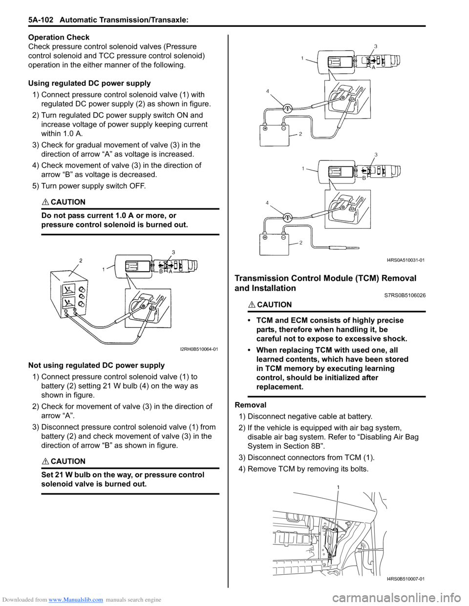
1) Connect pressure contro l solenoid valve (1) with
regulated DC power supply (2) as shown in figure.
2) Turn regulated DC power supply switch ON and increase voltage of power supply keeping current
within 1.0 A.
3) Check for gradual movement of valve (3) in the direction of arrow “A” as voltage is increased.
4) Check movement of valve (3) in the direction of arrow “B” as voltage is decreased.
5) Turn power supply switch OFF.
CAUTION!
Do not pass current 1.0 A or more, or
pressure control solenoid is burned out.
Not using regulated DC power supply 1) Connect pressure control solenoid valve (1) to battery (2) setting 21 W bulb (4) on the way as
shown in figure.
2) Check for movement of valve (3) in the direction of arrow “A”.
3) Disconnect pressure control solenoid valve (1) from battery (2) and check movement of valve (3) in the
direction of arrow “B” as shown in figure.
CAUTION!
Set 21 W bulb on the way, or pressure control
solenoid valve is burned out.
Transmission Control Module (TCM) Removal
and Installation
S7RS0B5106026
CAUTION!
• TCM and ECM consists of highly precise
parts, therefore when handling it, be
careful not to expose to excessive shock.
• When replacing TCM with used one, all learned contents, which have been stored
in TCM memory by executing learning
control, should be initialized after
replacement.
Removal
1) Disconnect negative cable at battery.
2) If the vehicle is equipped with air bag system, disable air bag system. Refer to “Disabling Air Bag
System in Section 8B”.
3) Disconnect connectors from TCM (1).
4) Remove TCM by removing its bolts.
I2RH0B510064-01
I4RS0A510031-01
1
I4RS0B510007-01
Page 756 of 1496

Downloaded from www.Manualslib.com manuals search engine 5A-112 Automatic Transmission/Transaxle:
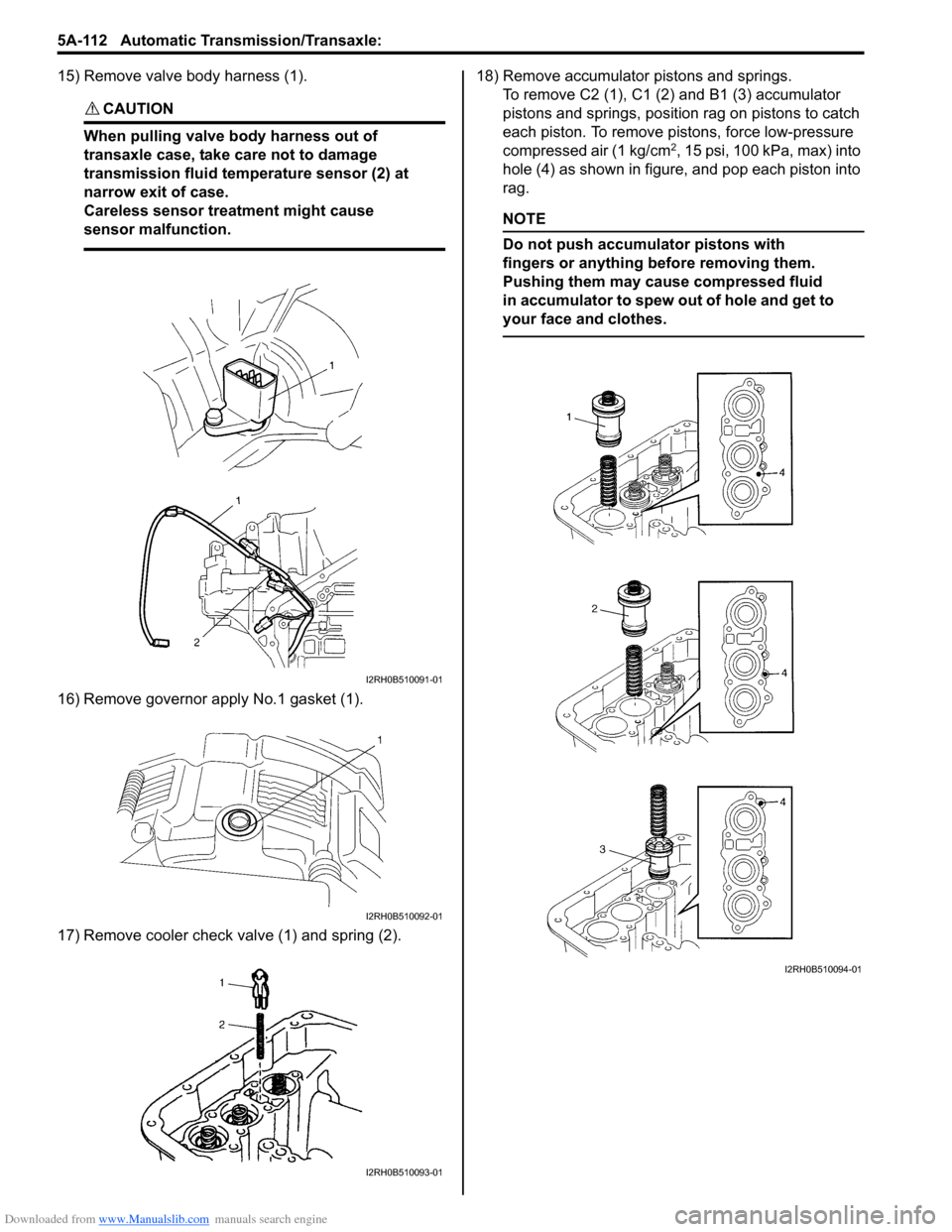
15) Remove valve body harness (1).
CAUTION!
When pulling valve body harness out of
transaxle case, take care not to damage
transmission fluid temperature sensor (2) at
narrow exit of case.
Careless sensor treatment might cause
sensor malfunction.
16) Remove governor apply No.1 gasket (1).
17) Remove cooler check valve (1) and spring (2).18) Remove accumulator pistons and springs.
To remove C2 (1), C1 (2) and B1 (3) accumulator
pistons and springs, position rag on pistons to catch
each piston. To remove pistons, force low-pressure
compressed air (1 kg/cm
2, 15 psi, 100 kPa, max) into
hole (4) as shown in figure, and pop each piston into
rag.
NOTE
Do not push accumulator pistons with
fingers or anything before removing them.
Pushing them may cause compressed fluid
in accumulator to spew out of hole and get to
your face and clothes.
I2RH0B510091-01
I2RH0B510092-01
I2RH0B510093-01
I2RH0B510094-01
Page 771 of 1496

Downloaded from www.Manualslib.com manuals search engine Automatic Transmission/Transaxle: 5A-127
Direct Clutch Assembly InspectionS7RS0B5106040
Clutch Discs, Plates and Retaining Plate
Check that sliding surfaces of discs, separator plates
and retaining plate are not worn hard or burnt. If
necessary, replace.
NOTE
• If disc lining is exfoliated, discolored, replace all discs.
• Before assembling new discs, soak them in A/T fluid for at least two hours.
Direct Clutch Return Spring Subassembly
Measure free length of direct clutch return spring.
Direct clutch return spring free length
“a”: 36.04 mm (1.419 in.)
NOTE
Do not apply excessive force when
measuring spring free length. Perform
measurement at several points.
Direct Clutch Piston
Shake direct clutch piston lightly and check that check
ball (1) is not stuck.
Blow in low pressure air (Max. 100 kPa, 1 kg/cm
2, 15 psi)
to check ball to check that there is no leakage.
I2RH0B510172-01
I2RH0B510173-01
I2RH0B510174-01
Page 817 of 1496

Downloaded from www.Manualslib.com manuals search engine Manual Transmission/Transaxle: 5B-3
Diagnostic Information and Procedures
Manual Transaxle Symptom DiagnosisS7RS0B5204001
Repair Instructions
Manual Transaxle Oil ChangeS7RS0B5206001
1) Before changing or inspecting oil, be sure to stop engine and lift vehicle horizontally.
2) With vehicle lifted up, check oil level and leakage. If leakage exists, correct it.
NOTE
Whenever vehicle is hoisted for any other
service work than oil change, also be sure to
check for oil leakage.
3) Remove oil filler plug (2).
4) Remove drain plug (1), and drain old oil. 5) Apply sealant to thread of drain plug (1), and tighten
it to specified torque.
“A”: Sealant 99000–31260 (SUZUKI Bond
No.1217G)
Tightening torque
Transaxle oil drain plug (a): 21 N·m (2.1 kgf-m,
15.5 lb-ft)
6) Pour new specified oil unt il oil level reaches bottom
of oil filler plug hole (3) as shown in figure.NOTE
It is highly recommended to use API GL-4
75W-90 gear oil.
Transaxle oil specification
: API GL-4 (For SAE classification, refer to
viscosity chart [A] in figure.)
Manual transaxle oil capacity
Reference: 2.0 liters (4.2/3.5 US/Imp. pt)
Condition Possible cause Correction / Reference Item
Gears slipping out of
mesh Worn shift fork shaft
Replace.
Worn shift fork or synchronizer sleeve Replace.
Weak or damaged locating springs Replace.
Worn bearings on input shaft or
countershaft Replace.
Worn chamfered tooth on sleeve and
gear Replace sleeve and gear.
Hard shifting Maladjusted gear select control cable Adjust.
Inadequate or insufficient lubricant Replenish.
Improper clutch pedal free travel Replace clutch master cylinder or clutch pedal
arm.
Distorted or broken clutch disc Replace.
Damaged clutch pressure plate Replace clutch cover.
Worn synchronizer ring Replace.
Worn chamfered tooth on sleeve or gear Replace sleeve or gear.
Worn gear shift / select control cables
joint Replace.
Distorted shift shaft Replace.
Worn gear shift / select control cables Replace.
Noise Inadequate or insufficient lubricant Replenish.
Damaged or worn bearing(s) Replace.
Damaged or worn gear(s) Replace.
Damaged or worn synchronizer parts Replace.
Page 854 of 1496

Downloaded from www.Manualslib.com manuals search engine 5C-2 Clutch:
Diagnostic Information and Procedures
Clutch System Symptom DiagnosisS7RS0B5304001
Repair Instructions
Clutch Pedal InspectionS7RS0B5306001
Cylinder Push Rod Play “A”1) Press clutch pedal (1) gradually with finger, stop when slight increase of resistance is felt and
measure how much pedal has moved (push rod
play) as represented by “A” as shown.
Push rod play
“A”: Max. 3 mm (0.12 in.)
2) If “A” is not within specification, replace master cylinder (3) or pedal arm (2). Clutch Pedal Free Travel “B”
1) Depress clutch pedal (1), stop the moment clutch resistance is felt, and measure how much pedal has
moved (clutch pedal free travel) as represented by
“B” in figure.
Clutch pedal free travel
“B”
: 2 – 8 mm (0.08 – 0.31 in.)
2) If “B” is not within specification, check pedal arm (2) and master cylinder (3) and replace defective part.
Condition Possible cause Correction / Reference Item
Slipping Improper clutch pedal free travel Replace master cylinder or clutch pedal arm.
Worn or oily clutch disc facing Replace disc.
Warped disc, pressure plate or flywheel
surface Replace disc, clutch cover or flywheel.
Weakened diaphragm spring Replace clutch cover.
Master cylinder piston or seal cup not
returning Replace master cylinder.
Dragging clutch Improper clutch pedal free travel Replace master cylinder or clutch pedal arm.
Weakened diaphragm spring, or worn
spring tip Replace clutch cover.
Rusted input shaft splines Lubricate.
Damaged or worn splines of transaxle
input shaft Replace input shaft.
Excessively wobbly clutch disc Replace disc.
Clutch facings broken or dirty with oil Replace disc.
Fluid leakage Repair or replace.
Clutch vibration Glazed (glass-like) clutch facings Repair or replace disc.
Clutch facings dirty with oil Replace disc.
Release bearing slides unsmoothly on
input shaft bearing retainer Lubricate or replace input shaft bearing
retainer.
Wobbly clutch disc, or poor facing
contact Replace disc.
Weakened torsion springs in clutch disc Replace disc.
Clutch disc rivets loose Replace disc.
Distorted pressure plate or flywheel
surface Replace clutch cover or flywheel.
Weakened engine mounting Replace engine mounting.
Loosened engine mounting bolt or nut Retighten engine mounting bolt or nut.
Noisy clutch Worn or broken release bearing Replace release bearing.
Input shaft front bearing worn down Replace input shaft bearing.
Excessive rattle of clutch disc hub Replace disc.
Cracked clutch disc Replace disc.
Pressure plate and diaphragm spring
rattling Replace clutch cover.
Grabbing clutch Clutch disc facings soaked with oil Replace disc.
Clutch disc facings excessively worn Replace disc.
Rivet heads showing out of facing Replace disc.
Weakened torsion springs Replace disc.
Page 856 of 1496

Downloaded from www.Manualslib.com manuals search engine 5C-4 Clutch:
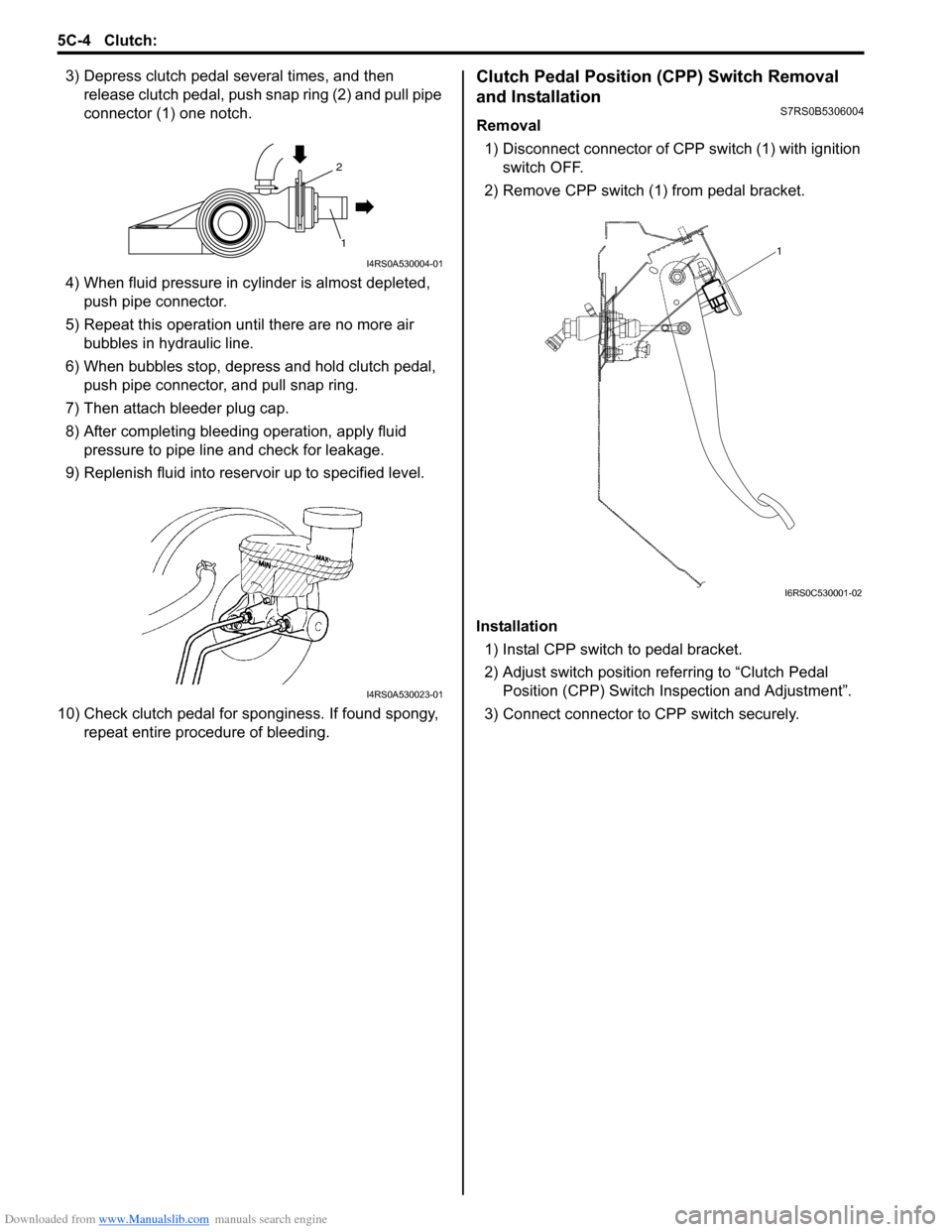
3) Depress clutch pedal several times, and then release clutch pedal, push snap ring (2) and pull pipe
connector (1) one notch.
4) When fluid pressure in cylinder is almost depleted, push pipe connector.
5) Repeat this operation until there are no more air bubbles in hydraulic line.
6) When bubbles stop, depress and hold clutch pedal, push pipe connector, and pull snap ring.
7) Then attach bleeder plug cap.
8) After completing bleeding operation, apply fluid pressure to pipe line and check for leakage.
9) Replenish fluid into reserv oir up to specified level.
10) Check clutch pedal for sponginess. If found spongy, repeat entire procedure of bleeding.Clutch Pedal Position (CPP) Switch Removal
and Installation
S7RS0B5306004
Removal
1) Disconnect connector of C PP switch (1) with ignition
switch OFF.
2) Remove CPP switch (1 ) from pedal bracket.
Installation 1) Instal CPP switch to pedal bracket.
2) Adjust switch position re ferring to “Clutch Pedal
Position (CPP) Switch Inspection and Adjustment”.
3) Connect connector to CPP switch securely.
2
1
I4RS0A530004-01
I4RS0A530023-01
1
I6RS0C530001-02
Page 863 of 1496

Downloaded from www.Manualslib.com manuals search engine Clutch: 5C-11
Clutch Cover1) Check diaphragm spring (1) for abnormal wear or damage.
2) Inspect pressure plate (2) for wear or heat spots.
3) If abnormality is found, replace clutch cover. Do not disassemble it into diaphragm spring and
pressure plate.
Flywheel
Check surface contacting clutch disc for abnormal wear
or heat spots. Replace or repair as required.
Clutch Release System Removal and
Installation
S7RS0B5306016
Removal 1) Remove release arm by loosening its bolt.
2) Take out release bearing by turning release shaft (1).
3) Drive out No.2 bush usin g special tool and hammer.
Release shaft seal will also be pushed out.
Special tool
(A): 09922–46010
4) Remove release shaft (1). 5) Install tap (M16 X 1.5) (1) to clutch release shaft
No.1 bush.
6) Pull No.1 bush out using tap (1) and special tools. Special tool
(B): 09923–46020
(C): 09930–30104
Installation 1) Drive in a new No.1 bush using special tools and
hammer, and then apply grease to bush inside.
Special tool
(A): 09943–88211
(B): 09923–46030
“A”: Grease 99000–25011 (SUZUKI Super
Grease A)
I3RM0A530015-01
I4RS0A530020-01
IYSY01531016-01
IYSY01531017-01
I3RM0A530016-01
Page 871 of 1496

Downloaded from www.Manualslib.com manuals search engine Steering General Diagnosis: 6A-2
Diagnostic Information and Procedures
Steering Symptom DiagnosisS7RS0B6104001
ConditionPossible cause Correction / Reference Item
Hard steering Tire not adequately inflated Inflate tires to proper pressure.
Malfunction of power steering system Check and correct.
Bind in tie-rod end ball studs or lower
ball joints Replace tie-rod end or front suspension arm.
Disturbed front wheel alignment Check and adjust front wheel alignment.
Bind in steering column Repair or replace steering column.
Rack and pinion adjustment Check and adjustment rack and pinion torque.
Too much play in steering Wheel bearings worn Replace wheel bearing.
Loose steering gear case bolts Tighten gear case bolts.
Faulty steering gear case assembly Replace steering gear case assembly.
Worn steering shaft joints Replace joint.
Worn tie-rod ends or tie-rod inside ball
joints Replace tie-rod end or tie-rod.
Worn lower ball joints Replace front suspension control arm.
Rack and pinion adjustment Check and adjustment rack and pinion torque.
Poor return ability Bind in tie-rod end ball studs Replace tie-rod end.
Bind in ball joints Replace front suspension control arm.
Bind in steering column Repair or replace steering column.
Disturbed front end alignment Check and adjust front end alignment.
Faulty steering gear case assembly Replace steering gear case assembly.
Tires not adequately inflated Adjust tire pressure.
Rack and pinion adjustment Check and adjustment rack and pinion torque.
Rack and pinion noise
(Rattle or chuckle) Loose steering gear case bolts
Tighten steering gear case bolts.
Rack and pinion adjustment Check and adjustment rack and pinion torque.
Faulty steering gear case assembly Replace steering gear case assembly.
Broken or other wise damaged wheel
bearing(s) Replace wheel bearing(s).
Wander or poor steering
stability Mismatched or uneven tires
Replace or inflate tires to proper pressure.
Loosen ball joints and tie-rod ends Replace suspension control arm or tie-rod end.
Faulty struts or mountings Replace strut or repair mounting.
Loose stabilizer bar Tighten or replace stabilizer bar or bush.
Broken or sagging springs Replace spring.
Rack and pinion adjustment Check and adjustment rack and pinion torque.
Disturbed front wheel alignment Check and adjust front wheel alignment.
Faulty steering gear case assembly Replace steering gear case assembly.
Erratic steering when
braking Worn wheel bearing(s)
Replace wheel bearing(s).
Broken or sagging spring(s) Replace coil spring(s).
Wheel tires are inflated unequally Inflate tires to proper pressure.
Disturbed front wheel alignment Check and adjust front wheel alignment.
Brakes not working in unison Check and repair brake system.
Leaking caliper Repair or replace caliper.
Warped discs Replace brake disc.
Badly worn brake pads Replace brake pads.