Page 1226 of 1496
Downloaded from www.Manualslib.com manuals search engine 9A-55 Wiring Systems:
A-6 A/T Control System Circuit DiagramS7RS0B910E007
GRN/YEL
Brakelight
switch
E47
GRN/YEL
C3520 8 7 19 18
9
85 3 6 2
GRN/YEL
Back-up light
20
RED
"D-8"
R
Transaxle
range sensor
TCM
L23
4
3 position switch
A/T
shift lock solenoid
A/T shift
lever assy
BLK/ORN
16
OFF ON
RED
1
RED
BLK
PNK/BLK
GRN/ORNLT GRN/BLK
C28
P
R ND 2L
PNK/BLK
1
2
E24 C36
17
PNK/BLK
BLK
63
BLK/ORN
18
BLK
14
L24
J/C
E45
L024
J/C
E43
J/C (CAN)
G16
BCM
DLC
G207
G375
E469
4
BLK
BLKBLK
11
J/C
G15
3
G36
E3814
E24
C3615
BLK/ORNBLK/ORN
5
23
GRN
RED/BLK
7
E24
C3619
E4114
RED/BLK
PNK
15A
STOP
LAMP8
GRN/WHT
GW
"D-7"
Brake light
3
4
J/B
L018
1
24
10ABACK
A
A
B
B A
A
PPL/WHT
PPL/WHT
PPL/WHT
PPL/WHT
A
A
D
E
LT GRN
P
"A-5"
VSS
PPL
25
R
C36E245
Lg
GY
PB
PW
9
A
Individual circuit
fuse box (No.1)
WHT/BLKRED/BLK
RBWB
BCM
"A-8"
14
6
BLK/ORN
15ARADIO40
G335
WHT/RED
B
B
J/C
G17
WHT/RED
16
J/C
E42
IF EQPD
E24 C36
I7RS0B910915-01
Page 1243 of 1496

Downloaded from www.Manualslib.com manuals search engine Wiring Systems: 9A-72
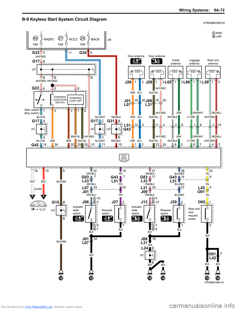
B-9 Keyless Start System Circuit DiagramS7RS0B910E018
BLKBLK
BLK
BLKBLK
YELBLU/REDPNK/BLKPPLGRY/BLU
YELBLU/REDPNK/BLKPPLGRY/BLU
YELBLU/REDPNK/BLKPPLGRY/BLU
G33
KLS
ECM
WHT/RED
WHT/REDWHT/RED
BLU/YEL
WHTRED
ORN
BLU/YEL
"C-3"
WR
G42143420
1819
BLK/ORN
BLK/ORN
9
5
J/B
15A RADIO
40
G348
10A
BACK
24
11
15A
ACC2
27
B
B
B
J/C
G17
B
A
A
J/C
BLU/WHT
BLU/WHT
C
C
J/C
G17
Main switch
(Key switch)
STEERING
LOCK PUSH SWITCH
G22456
1
O051
3
2
BRN29
BRN/YEL
301011RED/BLK
RED/BLK
B
B
J/C
Rear end
door
request
switch
G31
15ORN
ORN
ORN
1BLK/YEL
WHT/RED
378
STEERING
LOCK UNIT
Door antenna
L51
G4312
J01
L07 J261912
BLU
BLU
BLU
2
5
20
WHT/BLK
WHT/BLK6
Inside
antenna
2
12
GRN
GRN
5
9
LT GRN
LT GRN8
Luggage antenna
1
12
GRN/WHT
GRN/WHT
7
8
BLK/YEL
BLK/YEL
BLK/YEL
23
Door antenna
11
J09
L31 J28 L65 L66
WHT/GRN
WHT/GRN4
Rear end
antenna
3
12
RED/BLU
RED/BLU
3
10
L59
1912
WHT/RED
WHT/RED
WHT/RED
24
4
20
G17
B
B
J/C
G15
10
BLK
BLKBLK
32
J292
1
Request
switch
36
1914
J13
Actuator
state
switch
O01 L422
16
BLK
37
1814
J09
L31
J272
1
Request
switch
16
J06
Actuator
state
switch
34
BLK
BLK
33
18
J01
L07
(CAN) RHD
A
LHD
B
AB10
5AB5
10
AB8
7AB7
8
614G43
L5117G03 L337G43 L517G03 L33
423242324L42
O01
L31
J09
L07
J01
B
J/C
B
L24
I7RS0B910924-01
Page 1257 of 1496
Downloaded from www.Manualslib.com manuals search engine Wiring Systems: 9A-86
D-8 Back-Up Light System Circuit DiagramS7RS0B910E029
BLKBLK
141313
CC
C
J/C
L74CL28
Back-up light
switch
Back-up light (R)
RED
RED
RED/BLK
RED/BLK
ON
OFF J/B
10A
24BACK
E24
C3619
C302
1 20
L431L201
RED
RED
RED
M/T
L063
E4111
J/B
P R N D2LTransaxle
range sensor
RED/BLK
C28
R
RED
8
RED
"A-6"
TCM
R
E4114
7
5 5
Reverse signal pick-up
(For optional navigation)
5RED
(L)
Back-uplight (R)
(L)
M13A engine, M15A engine M16A engine
BLK
BLK
BLKBLK
F
M042
RED
REDRED
REDRED
1
M052
1
1L70
M012
3
A/T
I7RS0B910930-01
Page 1258 of 1496
Downloaded from www.Manualslib.com manuals search engine 9A-87 Wiring Systems:
D-9 Headlight Beam Leveling System Circuit DiagramS7RS0B910E030
10A
RED/BLK
GRN
GRN
RED/BLKRED/BLK
GRN
BLK
BLKBLK
switch
24BACK
RED/BLKRED/BLK
E59
G343E583
1
8E4114
12
G40 E38
G3653
4 10
G36
E3820 2
BLKBLK
Actuator (L)
Actuator (R)
R1
P0
P1
P2
P3
P4
R2
R3
R4
R5
R6
J/B
57
B
B
J/C
G31
I7RS0B910944-01
Page 1260 of 1496
Downloaded from www.Manualslib.com manuals search engine 9A-89 Wiring Systems:
E-1 Heater System Circuit DiagramS7RS0B910E032
BRN/WHT
GRN/WHT
10ABACK
24
M
BLK/RED
Relay
BLK/ORN
BLK/ORN
G15
J/C
G01
Air intake control
actuator3 7
1
GRNRED
9
G187
8
G31
J/C
4
G34
BCM
"A-8"GW
BCM
"B-3"
B
BRN
8
RED/YEL
RED/YEL
RED/BLK
RED/BLK
RED/BLK
1013 14 5 6
REAR
DEF REC
FRE
A/CHARF REC
CIRCUIT
HVAC control
unit
10
BB D
D B
B
B
1
RY
"D-4"
"B-3"
BR
J/B
G31
J/C
A A
A
A
BLK
11
A
BLKBLK
3
C
BLK
BLK
9
A
BLK/YEL
LHD RHD
I7RS0B910945-01
Page 1262 of 1496
Downloaded from www.Manualslib.com manuals search engine 9A-91 Wiring Systems:
E-2 Auto A/C System Circuit DiagramS7RS0B910E033
12G53
G51
G52
G51
G52 G52 G51
251211
11
15
17
12V
198
REDGRN
RED/BLK
GRN/RED
RED/YEL
RED/YELRED/BLK
RED/BLKBLU/WHT
M
7133G01
8G34
ILL
Auto A/C panel
Sunload sensor
DLC Auto
unit
Air intake control actuator
BACK
10A24
"A-5"
PW
"A-5"BW"D-4"RY
18
GRN/WHT
"A-8"GW
ECMBCMBCM
BLK/ORN
YEL/BLKPNK
5
PPL/WHT
PPL/WHT
BLK/ORNBLK/YEL
5V 5V
12V
J/B
7
YEL
YEL
"A-8"Y
109
G31
J/C
D
D
G15
J/C
B
B
BLK
BLK
G31
J/C
C
C
G16
J/C
C
C
G15
J/C
A A
11
BLK
A
G16
J/C
A
A
J/C
BG31B B
16
5
I7RS0B910932-01
Page 1283 of 1496

Downloaded from www.Manualslib.com manuals search engine Lighting Systems: 9B-1
Body, Cab and Accessories
Lighting Systems
Component Location
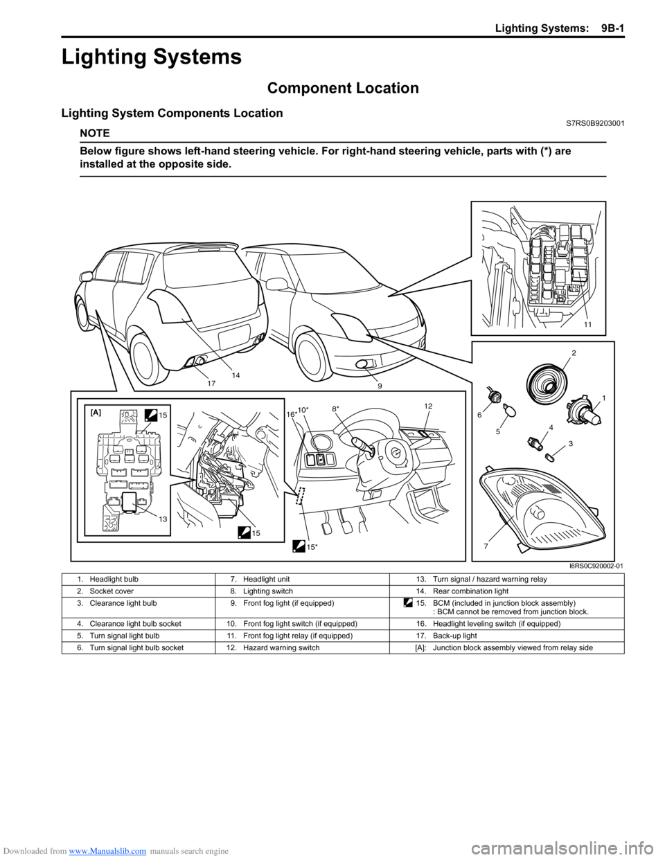
Lighting System Components LocationS7RS0B9203001
NOTE
Below figure shows left-hand steering vehicle. For right-hand steering vehicle, parts with (*) are
installed at the opposite side.
2
1
3
4
6
14
5
7
11
9
15
[A]
1515*
10*
8* 12
13
16*
17
I6RS0C920002-01
1. Headlight bulb 7. Headlight unit 13. Turn signal / hazard warning relay
2. Socket cover 8. Lighting switch 14. Rear combination light
3. Clearance light bulb 9. Front fog light (if equipped)15. BCM (included in junction block assembly)
: BCM cannot be removed from junction block.
4. Clearance light bulb socket 10. Front fog light switch (if equipped) 16. Headlight leveling switch (if equipped)
5. Turn signal light bulb 11. Front fog light relay (if equipped) 17. Back-up light
6. Turn signal light bulb socket 12. Hazard warning switch [A]: Junction block assembly viewed from relay side
Page 1286 of 1496

Downloaded from www.Manualslib.com manuals search engine 9B-4 Lighting Systems:
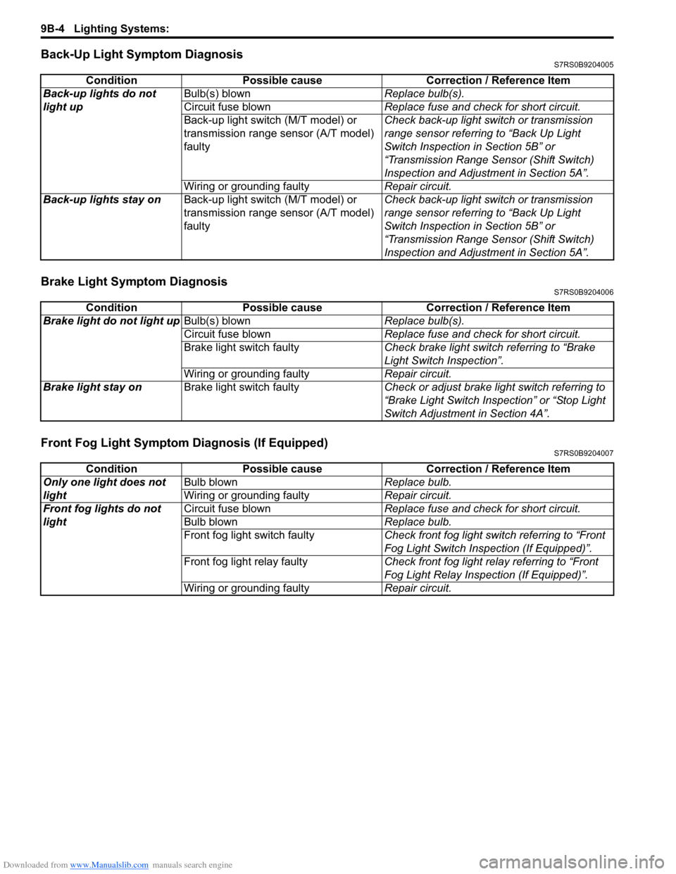
Back-Up Light Symptom DiagnosisS7RS0B9204005
Brake Light Symptom DiagnosisS7RS0B9204006
Front Fog Light Symptom Diagnosis (If Equipped)S7RS0B9204007
ConditionPossible cause Correction / Reference Item
Back-up lights do not
light up Bulb(s) blown
Replace bulb(s).
Circuit fuse blown Replace fuse and check for short circuit.
Back-up light switch (M/T model) or
transmission range sensor (A/T model)
faulty Check back-up light switch or transmission
range sensor referring to “Back Up Light
Switch Inspection in Section 5B” or
“Transmission Range Sensor (Shift Switch)
Inspection and Adjustment in Section 5A”.
Wiring or grounding faulty Repair circuit.
Back-up lights stay on Back-up light switch (M/T model) or
transmission range sensor (A/T model)
faulty Check back-up light switch or transmission
range sensor referring to “Back Up Light
Switch Inspection in Section 5B” or
“Transmission Range Sensor (Shift Switch)
Inspection and Adjustment in Section 5A”.
Condition
Possible cause Correction / Reference Item
Brake light do not light up Bulb(s) blown Replace bulb(s).
Circuit fuse blown Replace fuse and check for short circuit.
Brake light switch faulty Check brake light switch referring to “Brake
Light Switch Inspection”.
Wiring or grounding faulty Repair circuit.
Brake light stay on Brake light switch faulty Check or adjust brake light switch referring to
“Brake Light Switch Inspection” or “Stop Light
Switch Adjustment in Section 4A”.
ConditionPossible cause Correction / Reference Item
Only one light does not
light Bulb blown
Replace bulb.
Wiring or grounding faulty Repair circuit.
Front fog lights do not
light Circuit fuse blown
Replace fuse and check for short circuit.
Bulb blown Replace bulb.
Front fog light switch faulty Check front fog light switch referring to “Front
Fog Light Switch Inspection (If Equipped)”.
Front fog light relay faulty Check front fog light relay referring to “Front
Fog Light Relay Inspection (If Equipped)”.
Wiring or grounding faulty Repair circuit.