2006 SUZUKI SWIFT drive axle
[x] Cancel search: drive axlePage 787 of 1496
Downloaded from www.Manualslib.com manuals search engine Automatic Transmission/Transaxle: 5A-143
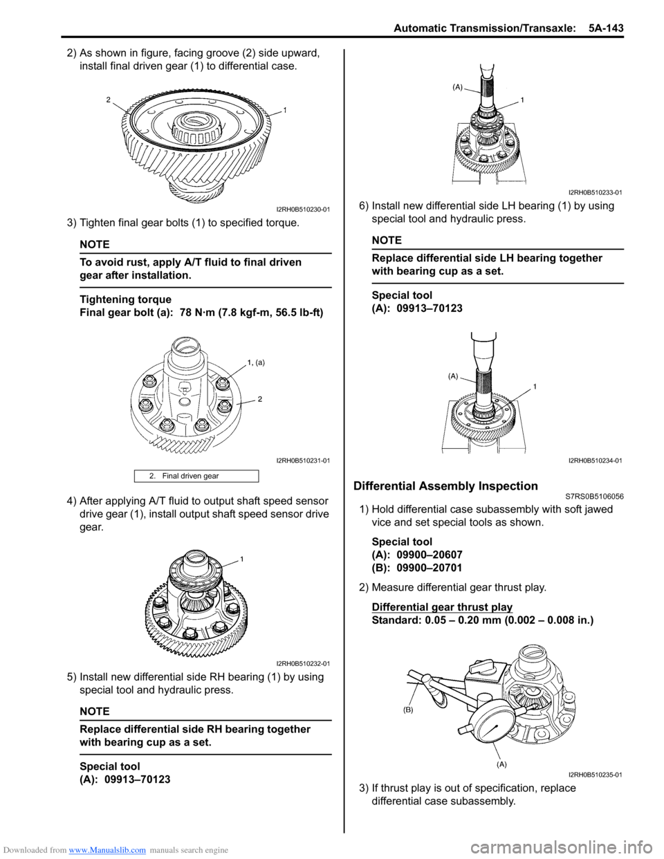
2) As shown in figure, facing groove (2) side upward, install final driven gear (1) to differential case.
3) Tighten final gear bolts (1) to specified torque.
NOTE
To avoid rust, apply A/T fluid to final driven
gear after installation.
Tightening torque
Final gear bolt (a): 78 N·m (7.8 kgf-m, 56.5 lb-ft)
4) After applying A/T fluid to output shaft speed sensor drive gear (1), install output shaft speed sensor drive
gear.
5) Install new differential side RH bearing (1) by using special tool and hydraulic press.
NOTE
Replace differential side RH bearing together
with bearing cup as a set.
Special tool
(A): 09913–70123 6) Install new differential side LH bearing (1) by using
special tool and hydraulic press.
NOTE
Replace differential side LH bearing together
with bearing cup as a set.
Special tool
(A): 09913–70123
Differential Assembly InspectionS7RS0B5106056
1) Hold differential case subassembly with soft jawed
vice and set special tools as shown.
Special tool
(A): 09900–20607
(B): 09900–20701
2) Measure differential gear thrust play.
Differential gear thrust play
Standard: 0.05 – 0.20 mm (0.002 – 0.008 in.)
3) If thrust play is out of specification, replace differential case subassembly.
2. Final driven gear
I2RH0B510230-01
I2RH0B510231-01
I2RH0B510232-01
I2RH0B510233-01
I2RH0B510234-01
I2RH0B510235-01
Page 796 of 1496

Downloaded from www.Manualslib.com manuals search engine 5A-152 Automatic Transmission/Transaxle:
12) Install 1st and reverse brake plate snap ring so that its both ends would be positioned in correct locations
as shown in figure.
13) Using special tools, meas ure 1st and reverse brake
piston stroke when compressed air (400 – 800 kPa,
4 – 8 kg/cm
2, 57 – 113 psi) is brown through oil hole.
Special tool
(A): 09900–20607
(B): 09900–20701
(C): 09952–06020
1st and reverse brake piston stroke
Standard: 0.791 – 1.489 mm (0.0311 – 0.0586 in.) 14) Install reduction drive gear (1) to transaxle case (3)
by using special tools and hydraulic press.
CAUTION!
• Do not use transaxle case as groundwork to press fit reduction drive gear.
• Do not give load more than 20 kN (2000 kg, 4410 lb) with hydraulic press. Otherwise, it
may result in damaging reduction drive
gear bearing.
NOTE
When replacing reduction drive gear, replace
it together with reduction driven gear as a
set.
Special tool
(A): 09951–18210
(B): 09944–78210
15) Install parking lock pawl (1) and spring (2). Apply A/T fluid to parking lock pawl sh aft, then insert it into
transaxle case.
[A]: Correct [B]: Incorrect
I2RH0B510268-01
I2RH0B510269-01
2. Stand that can slightly lift transaxle case.
I2RH0B510270-01
I2RH0B510271-01
Page 797 of 1496
Downloaded from www.Manualslib.com manuals search engine Automatic Transmission/Transaxle: 5A-153
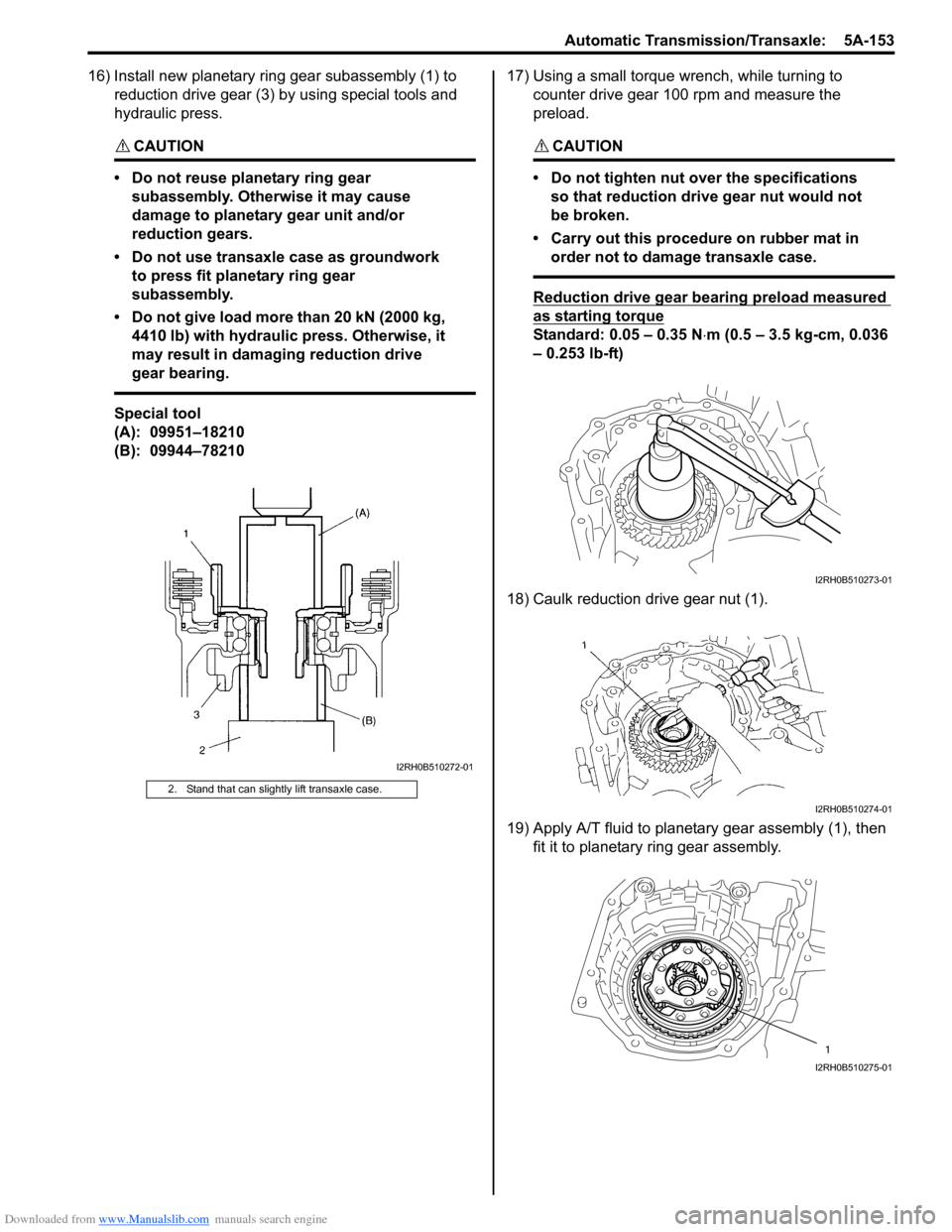
16) Install new planetary ring gear subassembly (1) to reduction drive gear (3) by using special tools and
hydraulic press.
CAUTION!
• Do not reuse planetary ring gear subassembly. Otherwise it may cause
damage to planetary gear unit and/or
reduction gears.
• Do not use transaxle case as groundwork to press fit planetary ring gear
subassembly.
• Do not give load more than 20 kN (2000 kg, 4410 lb) with hydraulic press. Otherwise, it
may result in damaging reduction drive
gear bearing.
Special tool
(A): 09951–18210
(B): 09944–78210 17) Using a small torque
wrench, while turning to
counter drive gear 100 rpm and measure the
preload.
CAUTION!
• Do not tighten nut over the specifications so that reduction drive gear nut would not
be broken.
• Carry out this procedure on rubber mat in order not to damage transaxle case.
Reduction drive gear bearing preload measured
as starting torque
Standard: 0.05 – 0.35 N ⋅m (0.5 – 3.5 kg-cm, 0.036
– 0.253 lb-ft)
18) Caulk reduction drive gear nut (1).
19) Apply A/T fluid to planetary gear assembly (1), then fit it to planetary ring gear assembly.
2. Stand that can slightly lift transaxle case.
I2RH0B510272-01
I2RH0B510273-01
I2RH0B510274-01
1
I2RH0B510275-01
Page 810 of 1496
Downloaded from www.Manualslib.com manuals search engine 5A-166 Automatic Transmission/Transaxle:
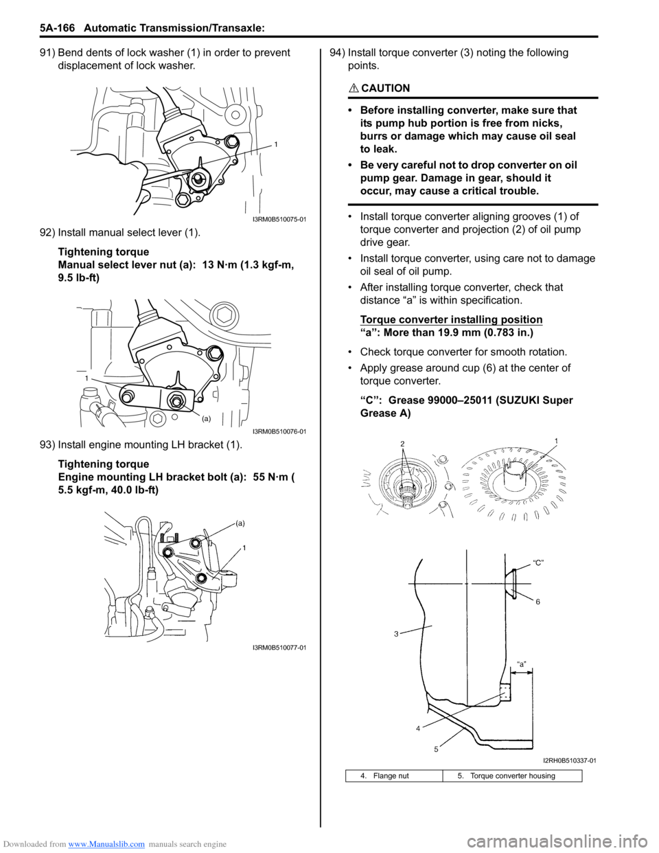
91) Bend dents of lock washer (1) in order to prevent displacement of lock washer.
92) Install manual select lever (1). Tightening torque
Manual select lever nut (a): 13 N·m (1.3 kgf-m,
9.5 lb-ft)
93) Install engine mounting LH bracket (1). Tightening torque
Engine mounting LH bracket bolt (a): 55 N·m (
5.5 kgf-m, 40.0 lb-ft) 94) Install torque converter (3) noting the following
points.
CAUTION!
• Before installing converter, make sure that its pump hub portion is free from nicks,
burrs or damage which may cause oil seal
to leak.
• Be very careful not to drop converter on oil pump gear. Damage in gear, should it
occur, may cause a critical trouble.
• Install torque converter aligning grooves (1) of torque converter and projection (2) of oil pump
drive gear.
• Install torque converter, using care not to damage oil seal of oil pump.
• After installing torque converter, check that distance “a” is within specification.
Torque converter installing position
“a”: More than 19.9 mm (0.783 in.)
• Check torque converter for smooth rotation.
• Apply grease around cup (6) at the center of torque converter.
“C”: Grease 99000–25011 (SUZUKI Super
Grease A)
1
I3RM0B510075-01
1
(a)
I3RM0B510076-01
I3RM0B510077-01
4. Flange nut 5. Torque converter housing
I2RH0B510337-01
Page 811 of 1496

Downloaded from www.Manualslib.com manuals search engine Automatic Transmission/Transaxle: 5A-167
Specifications
Tightening Torque SpecificationsS7RS0B5107001
NOTE
The specified tightening torque is also described in the following.
“Select Cable Components”
“Automatic Transaxle Unit Components”
“Automatic Transaxle Assembly Components”
“Oil Pump Assembly Components”
“Transaxle Rear Cover (O/D and 2nd Coast Brake Piston) Assembly Components”
“Valve Body Assembly Components”
“Differential Assembly Components”
Reference:
For the tightening torque of fastener not specified in this section, refer to “Fasteners Information in Section 0A”.
Fastening part
Tightening torque
Note
N ⋅mkgf-mlb-ft
A/T fluid drain plug 171.7 12.5 �) / �) / �)
Transmission range sensor bolt 5.5 0.55 4.0�) / �)
Output shaft speed sensor bolt 131.3 9.5 �) / �)
Input shaft speed sensor bolt 5.5 0.55 4.0�)
Valve body harness connector bolt 7.00.7 5.0 �)
Shift solenoid bolt 111.1 8.0 �)
Oil strainer bolt 101.0 7.5 �) / �)
Oil pan bolt 7.00.7 5.0 �) / �)
Transaxle and engine fastening bolt and nut 85 8.5 61.5�)
Drive plate to torque converter bolt 252.5 18.0 �)
Transaxle stiffener bolt 555.5 40�)
Starter motor bolt and nut 505.0 36.5 �)
Oil pump subassembly bolt 101.0 7.5 �)
Rear cover plug 7.5 0.75 5.5�)
Solenoid valve bolt 111.1 8.0 �)
Final gear bolt 787.8 56.5 �)
Torque converter housing plug 7.5 0.75 5.5�)
Lubrication tube clamp bolt 5.5 0.55 4.0�)
Fluid reservoir RH plate bolt 5.5 0.55 4.0�)
Torque converter housing bolt 292.9 21�) / �) / �)
Manual detent spring bolt 101.0 7.5 �)
Parking lock pawl bracket bolt 7.5 0.75 5.5�)
Rear cover bolt 252.5 18.0 �)
Fluid reservoir LH plate bolt 101.0 7.5 �)
Oil pump assembly bolt 252.5 18.0 �)
Transaxle case plug 7.5 0.75 5.5�)
Valve body harness connector bolt 5.5 0.55 4.0�)
Valve body bolt 111.1 8.0 �)
Fluid outlet union 252.5 18.0 �)
Fluid cooler pipe union bolt 222.2 16.0 �)
Fluid cooler pipe bracket bolt 101.0 7.5 �)
Fluid filler tube bolt 101.0 7.5 �)
Input shaft speed sensor bolt 111.1 8.0 �)
Harness bracket bolt 232.3 17.0 �)
Select cable clamp bolt 101.0 7.5 �)
Transmission range sensor lock nut 70.7 5.0 �)
Manual select lever nut 131.3 9.5 �)
Engine mounting LH bracket bolt 555.5 40.0
�)
Page 815 of 1496
Downloaded from www.Manualslib.com manuals search engine Manual Transmission/Transaxle: 5B-1
Transmission / Transaxle
Manual Transmission/Transaxle
General Description
Manual Transaxle Construction and ServicingS7RS0B5201001
The transaxle provides five forward speeds and one reverse speed by means of three synchromeshs and three shafts
(input shaft, countershaft and reverse gear shaft). All forward gears are in constant mesh, and reverse uses a sliding
idler gear arrangement.
The low speed synchronizer sleeve & hub is mounted on countershaft and engaged with countershaft 1st gear or 2nd
gear, while the high speed synchronizer sleeve & hub is don e on input shaft and engaged with input shaft 3rd gear or
4th gear. The 5th speed synchronizer sleev e & hub on input shaft is engaged with input shaft fifth gear mounted on the
input shaft.
To prevent the cracking noise from the reverse gear when shifting transaxle gear into the reverse gear, the reverse
shift braking device is used.
The device utilizes the 5th synchromesh, which is the lever synchro type, to appl y the brake on the input shaft rotation.
The double cone synchronizing mechanism is provided to 2nd gear synchromesh device for high performance of
shifting to 2nd gear.
The countershaft turns the final gear and differential assembly, thereby turning the front drive shafts which are
attached to the front wheels.
For servicing, it is ne cessary to use genuine sealant or its equivalent on mating surfaces of transaxle case which is
made of aluminum. The case fastening bolts must be tight ened to specified torque by means of torque wrench. It is
also important that all parts are thoroughly cleaned with cleaning fluid and air dried before reassembling.
Further, care must be taken to adjust preload of count ershaft taper roller bearings. New synchronizer rings are
prohibited from being lapped with respective gear cones by using lapping compound before they are assembled.
Page 818 of 1496
Downloaded from www.Manualslib.com manuals search engine 5B-4 Manual Transmission/Transaxle:
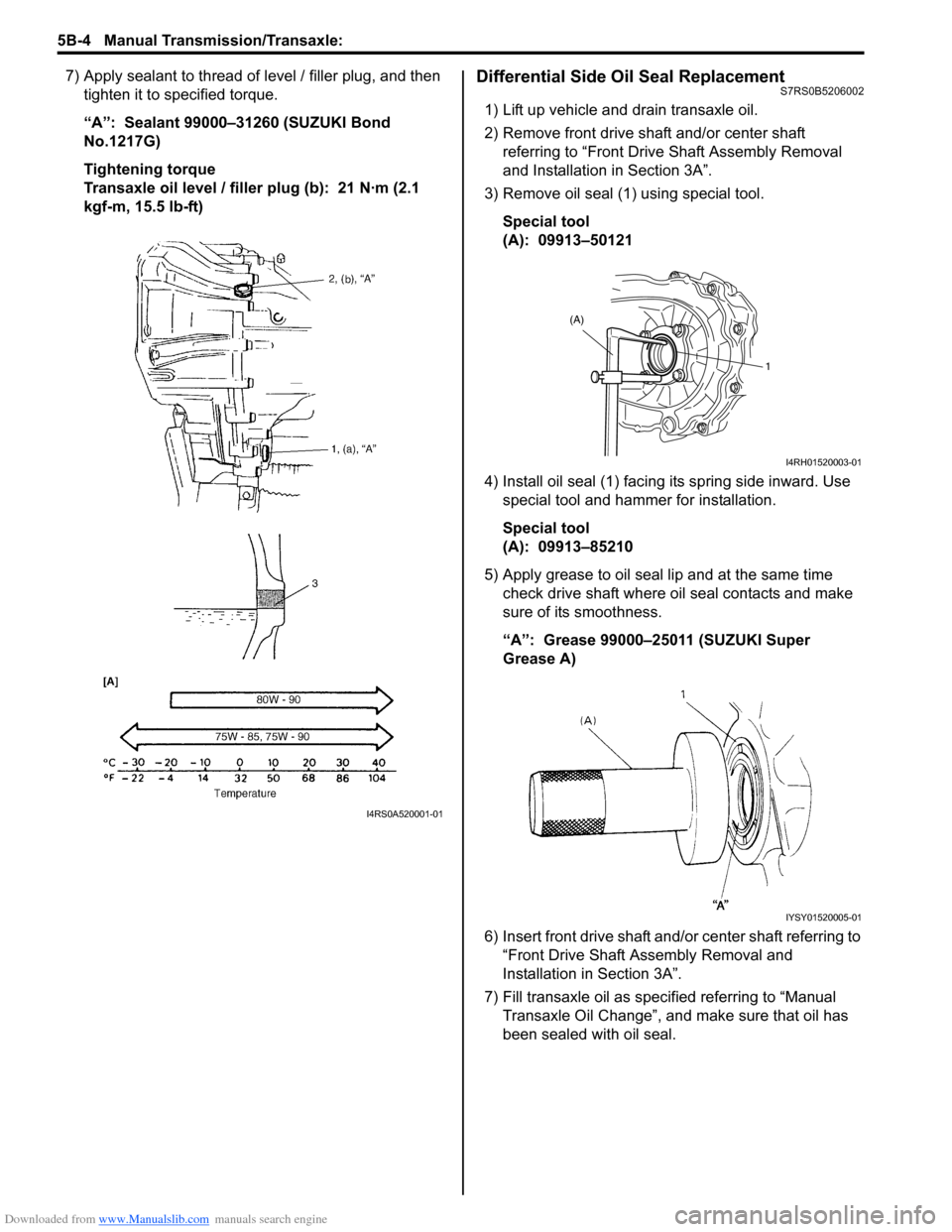
7) Apply sealant to thread of level / filler plug, and then
tighten it to specified torque.
“A”: Sealant 99000–31260 (SUZUKI Bond
No.1217G)
Tightening torque
Transaxle oil level / filler plug (b): 21 N·m (2.1
kgf-m, 15.5 lb-ft)Differential Side Oil Seal ReplacementS7RS0B5206002
1) Lift up vehicle and drain transaxle oil.
2) Remove front drive shaft and/or center shaft referring to “Front Driv e Shaft Assembly Removal
and Installation in Section 3A”.
3) Remove oil seal (1) using special tool.
Special tool
(A): 09913–50121
4) Install oil seal (1) facing its spring side inward. Use special tool and hammer for installation.
Special tool
(A): 09913–85210
5) Apply grease to oil seal lip and at the same time check drive shaft where oil seal contacts and make
sure of its smoothness.
“A”: Grease 99000–25011 (SUZUKI Super
Grease A)
6) Insert front drive shaft and/or center shaft referring to “Front Drive Shaft A ssembly Removal and
Installation in Section 3A”.
7) Fill transaxle oil as specified referring to “Manual Transaxle Oil Change”, and make sure that oil has
been sealed with oil seal.
I4RS0A520001-01
(A)
1
I4RH01520003-01
IYSY01520005-01
Page 823 of 1496

Downloaded from www.Manualslib.com manuals search engine Manual Transmission/Transaxle: 5B-9
Manual Transaxle Unit Dismounting and
Remounting
S7RS0B5206009
Dismounting1) Drain coolant and transaxle oil.
2) Remove coolant reservoir with reservoir hose.
3) Remove battery and tray.
4) Remove air cleaner case and resonator.
5) Disconnect gear shift and gear select control cables (1) while pressing claws (2) of clip (3).
6) Disconnect back up light switch coupler and undo wiring harness clamps.
7) Remove ground cable from transaxle.
8) Remove clutch operating cylinder with fluid hose from transaxle.
9) Remove water inlet No.2 pipe from transaxle.
10) Remove starting motor re ferring to “Starting Motor
Dismounting and Remounting in Section 1I”.
11) Remove transaxle to engine bolts (1) of upper side. 12) Support engine using supporting device (1).
CAUTION!
Do not apply supporting device to projection
part A. If do so, it may be deformed.
13) Remove front drive shafts and center shaft referring
to “Front Drive Shaft Assembly Removal and
Installation in Section 3A”.
14) Remove exhaust No.2 pipe referring to “Exhaust Pipe and Muffler Removal a nd Installation in Section
1K”.
15) Remove clutch housing lower plate (1).
1
2
3
I7RS0A521003-01
1
1
I4RS0A520018-01
1
A
I4RS0A520019-01
1I4RS0A520020-01