2006 SUZUKI SWIFT 200
[x] Cancel search: 200Page 522 of 1496

Downloaded from www.Manualslib.com manuals search engine 4B-6 Front Brakes:
5) To confirm that boot is fitted in its groove in cylinder
properly, pull piston out of cylinder a little but do not
take it all out.
NOTE
Boot’s face (1) should be at the same level
from cylinder’s face (2) all around.
6) Insert piston into cylinder by hand.
Front Disc Brake Caliper InspectionS7RS0B4206007
Pin Boot and Cylinder Boot
Check boots for breakage, crack and damage.
If defective, replace.
Piston Seal
Excessive or uneven wear of pad lining may indicate
unsmooth return of piston.
In such case, replace rubber seal.
Front Brake Disc Removal and InstallationS7RS0B4206008
CAUTION!
During removal, be care ful not to damage
brake flexible hose and not to depress brake
pedal.
Removal
1) Hoist vehicle and remove wheel.
2) Remove caliper assembly by removing caliper carrier bolts (2 pcs).
NOTE
Hang removed caliper with a wire hook or the
like so as to prevent brake hose from
bending and twisting excessively or being
pulled.
3) Pull brake disc off by using 8 mm bolts (1) (2 pcs).
I4RS0A420004-01
I2RH01420014-01
I2RH01420015-01
I2RH01420024-01
I2RH01420025-01
Page 523 of 1496
Downloaded from www.Manualslib.com manuals search engine Front Brakes: 4B-7
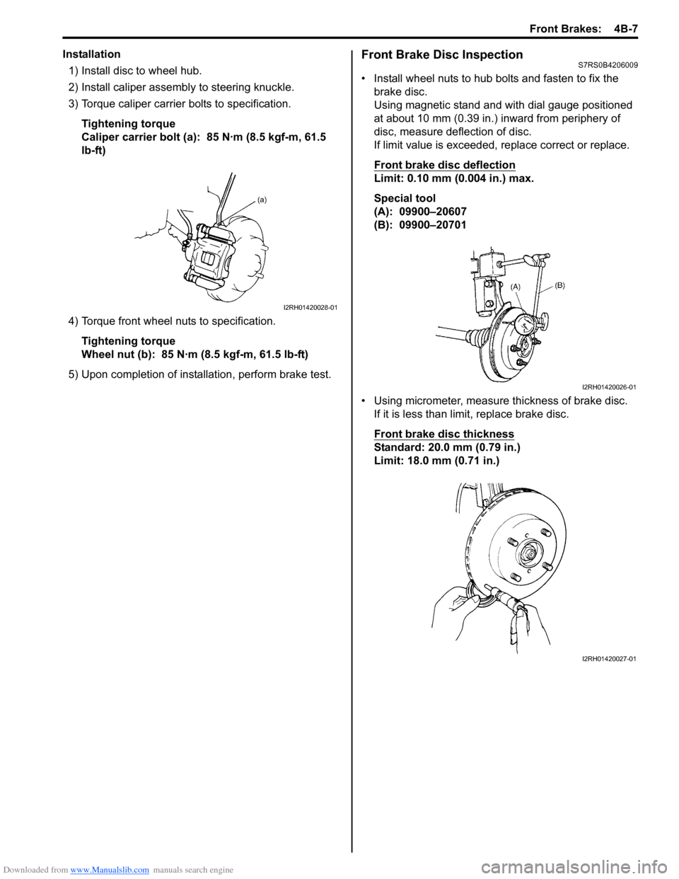
Installation1) Install disc to wheel hub.
2) Install caliper assemb ly to steering knuckle.
3) Torque caliper carrier bolts to specification.
Tightening torque
Caliper carrier bolt (a): 85 N·m (8.5 kgf-m, 61.5
lb-ft)
4) Torque front wheel nuts to specification. Tightening torque
Wheel nut (b): 85 N·m (8.5 kgf-m, 61.5 lb-ft)
5) Upon completion of installation, perform brake test.Front Brake Disc InspectionS7RS0B4206009
• Install wheel nuts to hub bolts and fasten to fix the brake disc.
Using magnetic stand and with dial gauge positioned
at about 10 mm (0.39 in.) inward from periphery of
disc, measure deflection of disc.
If limit value is exceeded, replace correct or replace.
Front brake disc deflection
Limit: 0.10 mm (0.004 in.) max.
Special tool
(A): 09900–20607
(B): 09900–20701
• Using micrometer, measure thickness of brake disc. If it is less than limit, replace brake disc.
Front brake disc thickness
Standard: 20.0 mm (0.79 in.)
Limit: 18.0 mm (0.71 in.)
I2RH01420028-01
I2RH01420026-01
I2RH01420027-01
Page 537 of 1496
Downloaded from www.Manualslib.com manuals search engine Parking Brake: 4D-2
Repair Instructions
Parking Brake Inspection and AdjustmentS7RS0B4406001
Inspection
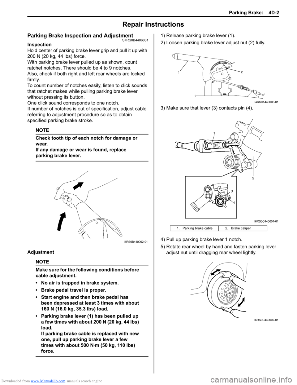
Hold center of parking brake lever grip and pull it up with
200 N (20 kg, 44 lbs) force.
With parking brake lever pulled up as shown, count
ratchet notches. There should be 4 to 9 notches.
Also, check if both right and left rear wheels are locked
firmly.
To count number of notches easily, listen to click sounds
that ratchet makes while pulling parking brake lever
without pressing its button.
One click sound corresponds to one notch.
If number of notches is out of specification, adjust cable
referring to adjustment procedure so as to obtain
specified parking brake stroke.
NOTE
Check tooth tip of each notch for damage or
wear.
If any damage or wear is found, replace
parking brake lever.
Adjustment
NOTE
Make sure for the following conditions before
cable adjustment.
• No air is trapped in brake system.
• Brake pedal travel is proper.
• Start engine and then brake pedal has been depressed at least 3 times with about
160 N (16.0 kg, 35.3 lbs) load.
• Parking brake lever (1) has been pulled up a few times with about 200 N (20 kg, 44 lbs)
load.
If parking brake cable is replaced with new
one, pull up parking brake lever a few
times with about 500 N ⋅m (50 kg, 110 lbs)
force.
1) Release parking brake lever (1).
2) Loosen parking brake lever adjust nut (2) fully.
3) Make sure that lever (3) contacts pin (4).
4) Pull up parking brake lever 1 notch.
5) Rotate rear wheel by hand and fasten parking lever adjust nut until dragging rear wheel lightly.
I4RS0B440002-01
1. Parking brake cable 2. Brake caliper
I4RS0A440003-01
I6RS0C440001-01
I6RS0C440002-01
Page 538 of 1496
Downloaded from www.Manualslib.com manuals search engine 4D-3 Parking Brake:
6) Release parking brake lever and then make sure that there is no drag in rear wheel.
If there is, repeats go to step 2).
7) Make sure that the number of notch is between 4 and 9 when operating parking brake lever.
8) If the number of notch is not between 4 and 9, replace parking brake cable and/or inspect rear
brake caliper.
Parking brake stroke
When lever is pulled up at 200 N (20kg, 44lbs) : 4
to 9 notches
Parking Brake Cable Removal and InstallationS7RS0B4406002
Removal
NOTE
When it is necessary to remove both right
and left parking brake cables, repeat below
steps 2) and 5) on right and left wheels.
1) Hoist vehicle.
2) Remove wheel.
3) Disconnect parking brake cable from equalizer (parking brake lever) and clamps.
4) Disconnect parking brake cable from lever referring to “Rear Disc Brake Caliper Removal and Installation
in Section 4C”.
5) Remove parking brake cable and parking cable bracket.
Installation
Install it by reversing removal procedure, noting the
following points.
• Install clamps properly referring to “Parking Brake Cable Construction”.
• Tighten bolts and nuts to specified torque referring to “Parking Brake Cable Construction”.
Tightening torque
Parking brake lever bolt: 25 N·m (2.5 kgf-m, 18.0
lb-ft)
Parking cable clamp bolt: 11 N·m (1.1 kgf-m, 8.0
lb-ft)
Parking cable bracket bolt: 25 N·m (2.5 kgf-m,
18.0 lb-ft)
• Adjust parking brake cable. Refer to “Parking Brake Inspection and Adjustment”.
• Check brake disc for dragging and brake system for proper performance. Brake test should be performed.
Parking Brake Lever Removal and InstallationS7RS0B4406003
Removal
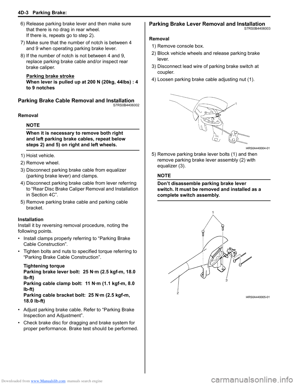
1) Remove console box.
2) Block vehicle wheels and release parking brake lever.
3) Disconnect lead wire of parking brake switch at coupler.
4) Loosen parking brake cable adjusting nut (1).
5) Remove parking brake lever bolts (1) and then remove parking brake lever assembly (2) with
equalizer (3).
NOTE
Don’t disassemble parking brake lever
switch. It must be removed and installed as a
complete switch assembly.
I4RS0A440004-01
I4RS0A440005-01
Page 543 of 1496
Downloaded from www.Manualslib.com manuals search engine ABS: 4E-4
Schematic and Routing Diagram
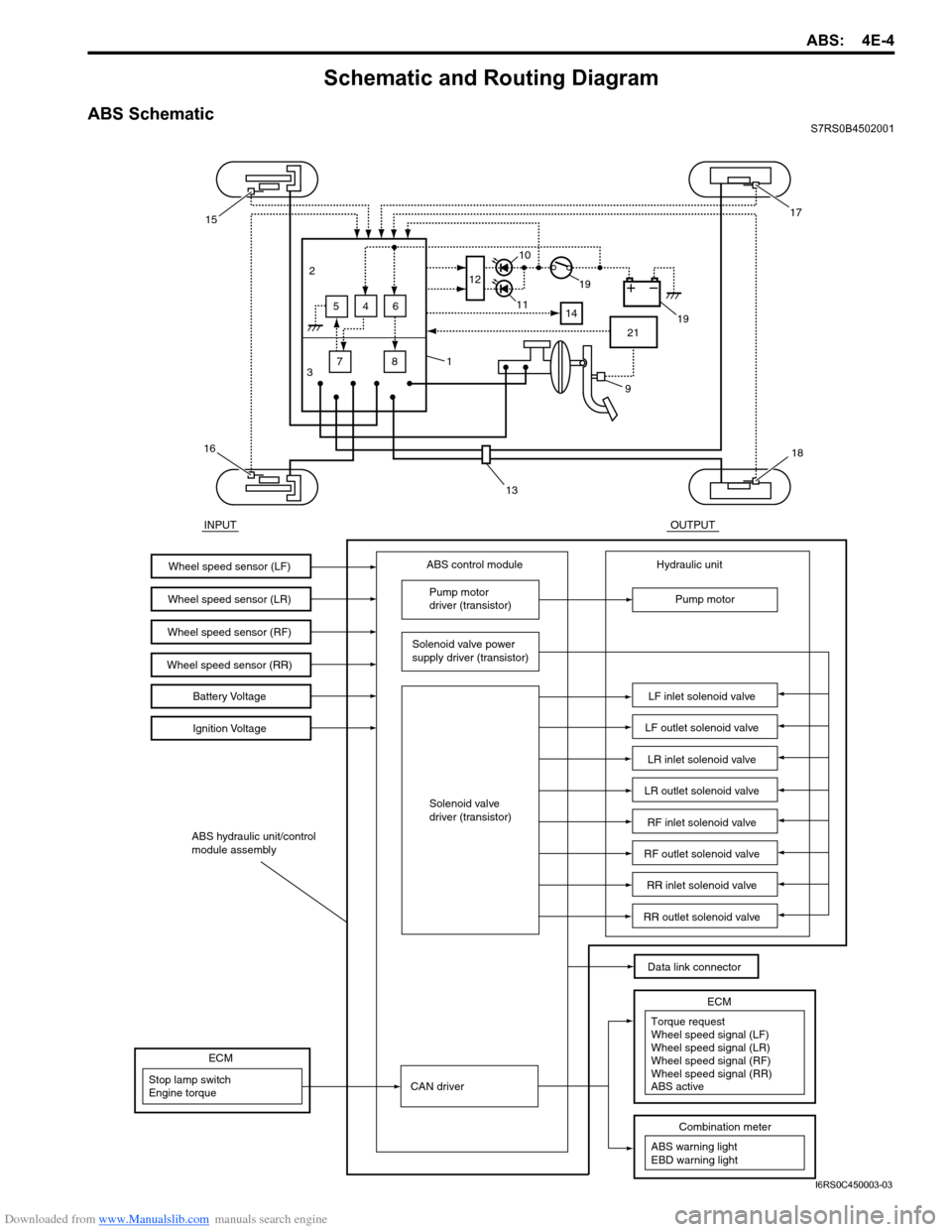
ABS SchematicS7RS0B4502001
INPUTOUTPUT
ABS control moduleWheel speed sensor (LF)
Wheel speed sensor (LR)
Wheel speed sensor (RF)Battery Voltage
Ignition Voltage
Pump motor
driver (transistor)
Solenoid valve power
supply driver (transistor)
Solenoid valve
driver (transistor) Hydraulic unit
Pump motor
LF inlet solenoid valve
LF outlet solenoid valve
LR inlet solenoid valve
LR outlet solenoid valve
RF inlet solenoid valve
RF outlet solenoid valve
RR inlet solenoid valve
RR outlet solenoid valve
Data link connector
ABS hydraulic unit/control
module assembly
Wheel speed sensor (RR)
3 7
2
645
8 12
14
21
15
16
1
13
18
17
19
19
11
10
9
CAN driverStop lamp switch
Engine torque
ECM
ABS warning light
EBD warning light
Combination meter
Torque request
ECMWheel speed signal (LF)
Wheel speed signal (LR)
Wheel speed signal (RF)
Wheel speed signal (RR)
ABS active
I6RS0C450003-03
Page 544 of 1496
Downloaded from www.Manualslib.com manuals search engine 4E-5 ABS:
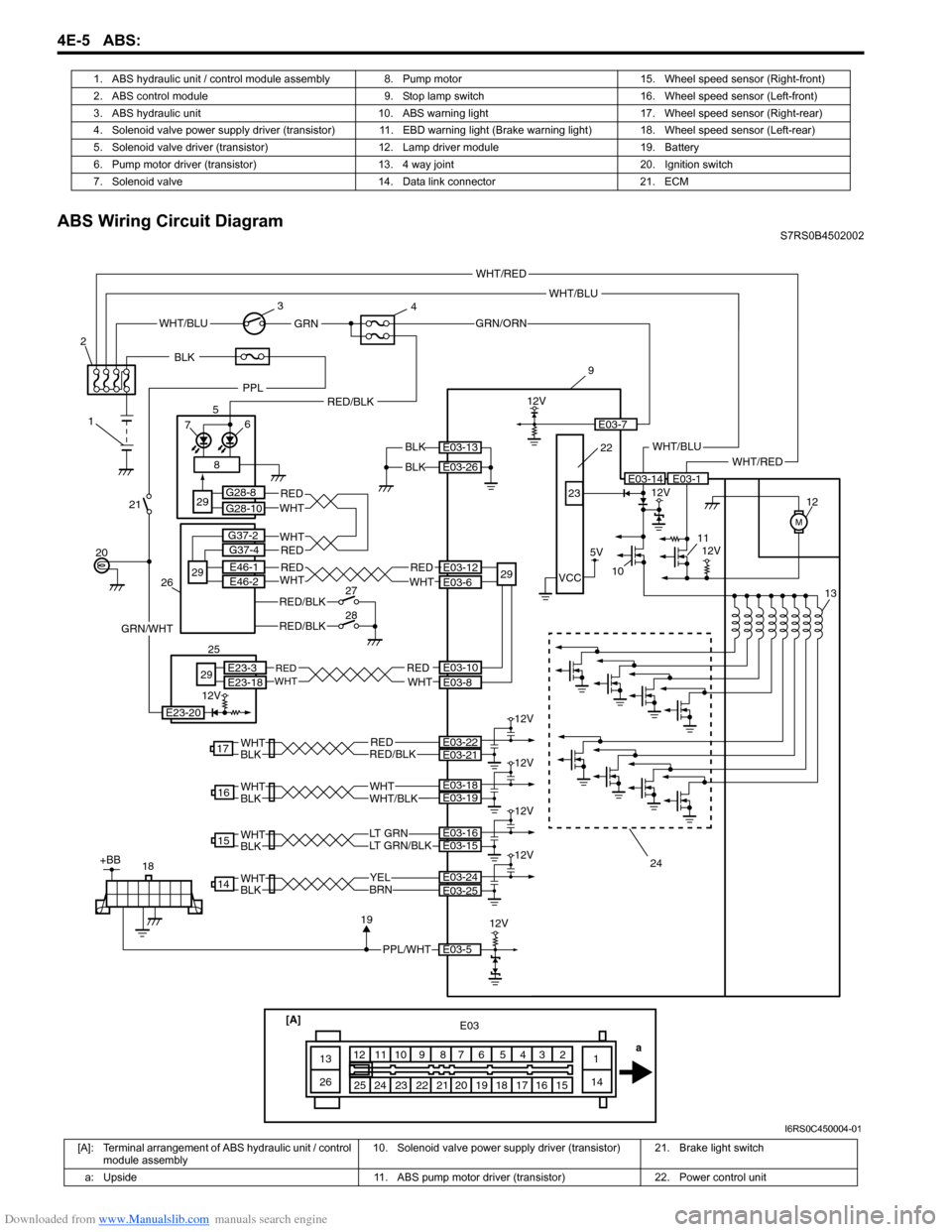
ABS Wiring Circuit DiagramS7RS0B4502002
1. ABS hydraulic unit / control module assembly 8.
Pump motor 15. Wheel speed sensor (Right-front)
2. ABS control module 9. Stop lamp switch 16. Wheel speed sensor (Left-front)
3. ABS hydraulic unit 10. ABS warning light 17. Wheel speed sensor (Right-rear)
4. Solenoid valve power supply driver (transistor) 11. EBD warnin g light (Brake warning light) 18. Wheel speed sensor (Left-rear)
5. Solenoid valve driver (transistor) 12. Lamp driver module 19. Battery
6. Pump motor driver (transistor) 13. 4 way joint 20. Ignition switch
7. Solenoid valve 14. Data link connector 21. ECM
[A]
14
1516171819202122232425 1
23456789101112
13
26 E03
a
WHT/BLU
BLKWHT/BLU
M
12V
9
10 11 12
13
BLKE03-14E03-1
E03-13
E03-26
YELBRN
14E03-24
LT GRN/BLKLT GRN
15
WHTWHT/BLK
16
RED
WHTBLK
WHTBLK
WHTBLK
WHTBLKRED/BLK
17
12V
PPL/WHT
18E03-5
1912V
5V
12V
23
24
VCC22
E03-25
E03-15E03-16
E03-19E03-18
E03-22E03-21
WHT/RED
WHT/RED
+BB
GRN/ORN
E03-7
WHT/BLUGRN
1
2
3
4
8
RED/BLK
E03-12
E03-6
RED
WHTE03-10E03-8
REDWHT
20 7
6
529
29
G28-8
G28-10
25
29
E23-3E23-18
GRN/WHT
21
PPL
12V
E23-20
12V
12V
12V
12V
REDWHTE46-1
E46-2
BLK
RED/BLK
RED/BLK
RED
RED
WHT
WHT
27
28
26
29
G37-2
G37-4
REDWHT
I6RS0C450004-01
[A]: Terminal arrangement of ABS hydraulic unit / control module assembly 10. Solenoid valve power supply driver
(transistor) 21. Brake light switch
a: Upside 11. ABS pump motor driver (transistor) 22. Power control unit
Page 582 of 1496
Downloaded from www.Manualslib.com manuals search engine 4F-8 Electronic Stability Program:
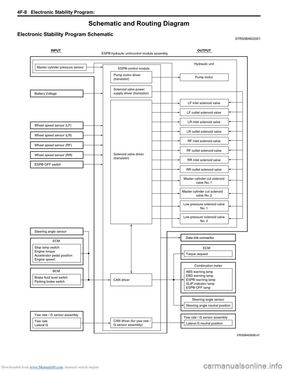
Schematic and Routing Diagram
Electronic Stability Program SchematicS7RS0B4602001
INPUTOUTPUT
ESP® control module
Wheel speed sensor (LF)
Wheel speed sensor (LR)
Wheel speed sensor (RF) Battery VoltageMaster cylinder pressure sensor
Pump motor driver
(transistor)
Solenoid valve power
supply driver (transistor)
Solenoid valve driver
(transistor)
CAN driver
CAN driver (for yaw rate /
G sensor assembly) Hydraulic unit
Pump motor
LF inlet solenoid valve
LF outlet solenoid valve
LR inlet solenoid valve
LR outlet solenoid valve
RF inlet solenoid valve
RF outlet solenoid valve
RR inlet solenoid valve
RR outlet solenoid valve
Data link connector
Data link connector
ESP® hydraulic unit/control module assembly
Wheel speed sensor (RR)
Master cylinder cut solenoid valve No. 1
Master cylinder cut solenoid
valve No. 2
Low pressure solenoid valve No. 1
Low pressure solenoid valveNo. 2
Stop lamp switch
Engine torque
Accelerator pedal position
Engine speed ECM
Brake fluid level switch
Parking brake switch
BCM
Steering angle sensor
ESP® OFF switch
Yaw rate
Lateral G Yaw rate / G sensor assembly
ABS warning lamp
EBD warning lamp
ESP® warning lamp
SLIP indicator lamp
ESP® OFF lampCombination meter
Torque request
ECM
Steering angle neutral positionSteering angle sensor
Yaw rate / G sensor assembly
Lateral G neutral position
I7RS0B460006-01
Page 583 of 1496
Downloaded from www.Manualslib.com manuals search engine Electronic Stability Program: 4F-9
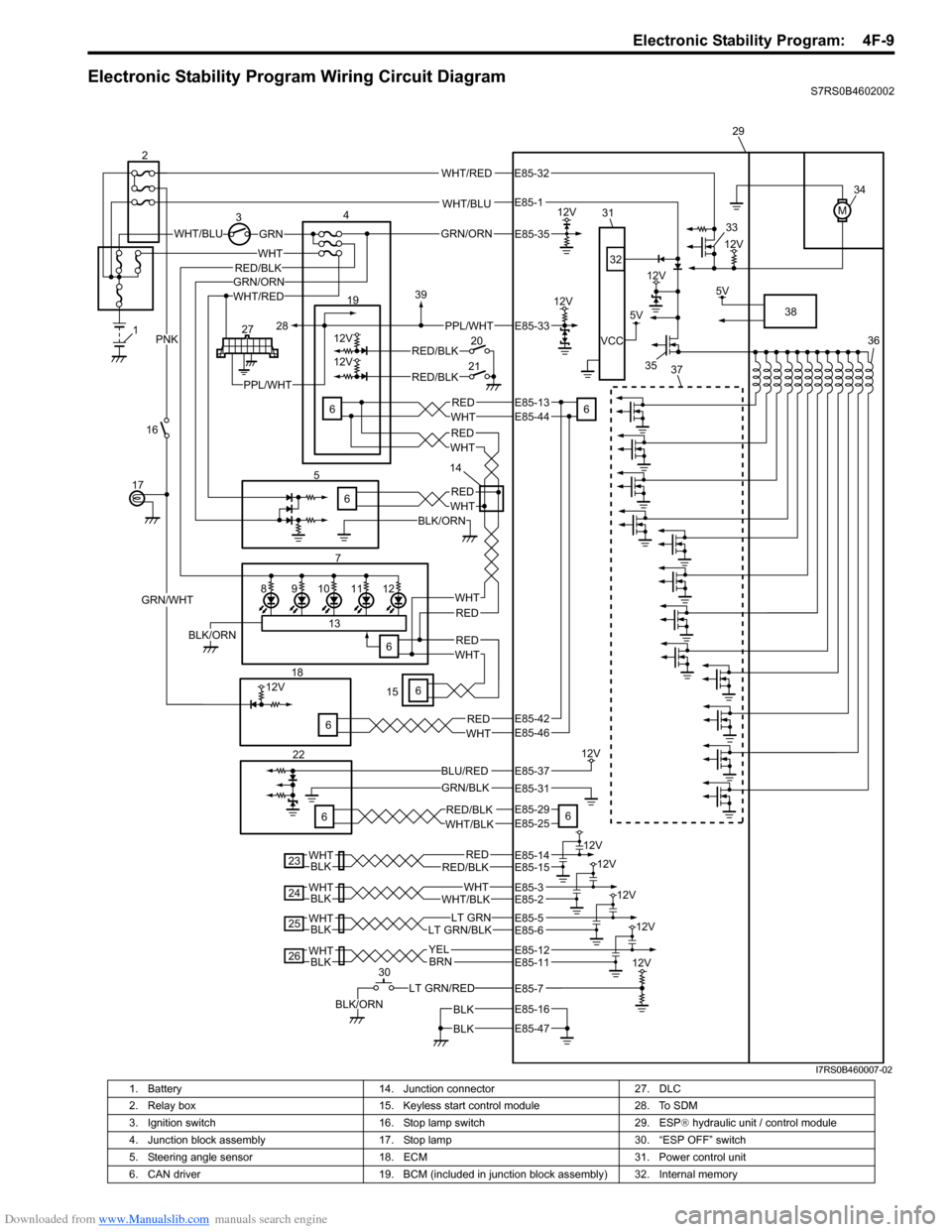
Electronic Stability Program Wiring Circuit DiagramS7RS0B4602002
WHT/BLU
WHT/BLUGRN
M
12V3
12V
5V
12V
VCC
WHT/RED
WHT
7
REDWHT
12V
12V
6 19
20
21RED/BLK
RED/BLK
GRN/WHT
PNK
12V
GRN/BLK
5V
LT GRN/RED
BLK/ORN
4
16
17
186
22
6 29
30 34
36
38
33
35
32
31
6
6 37
BLK
BLK
RED/BLKRED12V
BLKWHT
23
WHT/BLKWHT
12V
BLKWHT
24
BLKWHTLT GRN/BLKLT GRN
12V
25
BLKWHTBRN
12V
26YEL
12V
98101211
13
6BLK/ORN
1
227
5
WHT/REDGRN/ORN
BLK/ORN
REDWHT
REDWHT
PPL/WHT
6
REDWHT
REDWHT
6
REDWHT
RED/BLK
PPL/WHT
28
39
15 14
BLU/RED
GRN/ORN
12V
12V
E85-35
E85-33
E85-13E85-44
E85-46
E85-29E85-25
E85-37
E85-31
E85-14E85-15
E85-12E85-11
E85-16
E85-47
E85-3
E85-32
E85-1
E85-2
E85-5E85-6
E85-7
E85-42
RED/BLKWHT/BLK
I7RS0B460007-02
1. Battery 14. Junction connector 27. DLC
2. Relay box 15. Keyless start control module 28. To SDM
3. Ignition switch 16. Stop lamp switch 29. ESP® hydraulic unit / control module
4. Junction block assembly 17. Stop lamp 30. “ESP OFF” switch
5. Steering angle sensor 18. ECM 31. Power control unit
6. CAN driver 19. BCM (included in junction block assembly) 32. Internal memory